

Page 1

6121 Baker Road,
Suite 108
Minnetonka, MN 55345
www.chtechnology.com
Phone (952) 933-6190
Fax (952) 933-6223
1-800-274-4284
Thank you for downloading this document from C&H Technology, Inc.
Please contact the C&H Technology team for the following questions -
Technical
Application
Assembly
Availability
Pricing
Phone – 1-800-274-4284
E-Mail – sales@chtechnology.com
www.chtechnology.com - SPECIALISTS IN POWER ELECTRONIC COMPONENTS AND ASSEMBLIES - www.chtechnology.com
Page 2
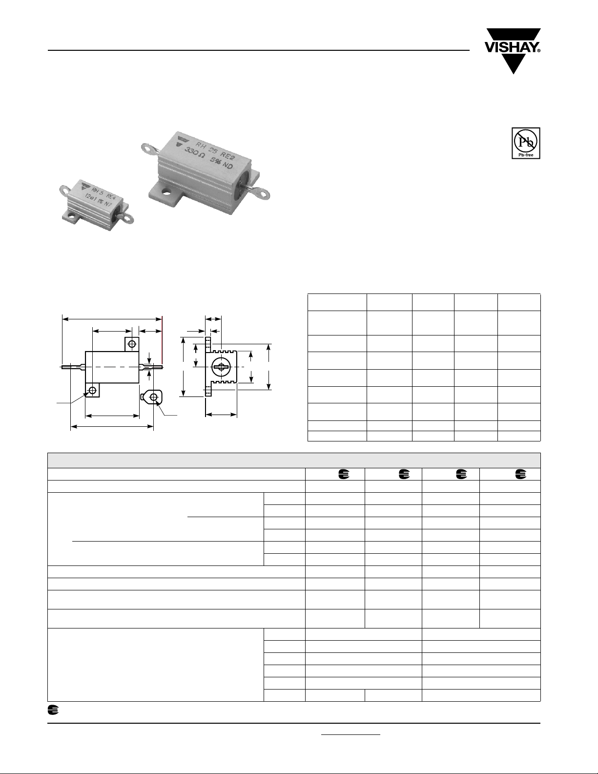
RH
Vishay Sfernice
Heatsink Encased Wirewound Power Resistors
FEATURES
• 5 Watt to 50 Watt at 25 °C
• NF C 83-210
• CECC 40 203
• High stability < 0.05 % year
• Low temperature coefficient typically ± 15 ppm/°C
• Wide range of values from 0.006 Ω to 130 kΩ
• Termination = Sn/Ag/Cu
Encased in a compact and light heatsink offering complete environmental protection, great mechanical strength and easy
mounting. Non inductive versions can be supplied under the RHNI designation (please indicate required specifications and
frequency range upon ordering).
RoHS
COMPLIANT
DIMENSIONS in millimeters
Ø K
A
RH
D
E
Q
F
Ø 2
J
Ø P
M
N
H
B
G
L
MODEL AND
STYLE
A
B ± 0.2
D ± 0.2
E ± 0.5
F
G ± 1
H ± 0.7
J ± 0.5
Ø K ± 0.1
L max.
M ± 0.5
N ± 0.3
Ø P min.
Q 25.3 ± 1.5 30.6 ± 1.5 44.6 ± 1.3 66.5 ± 1.4
Weight in g 3 8.8 16.5 30.8
RH5 RH10 RH25 RH50
28.5 ± 1.5
12.5
11.3
16.3
6.8 ± 1.5197.9 ± 1.52811.1 ± 1.55011 ± 1.2
8.5
6.2
16.4
2.4
8.9
4.3
1.6
2.1
35 ± 1.5
15.9
14
11
7.9
20.6
2.4
11
5.6
2
2.1
49 ± 1.3
19.8
18.3
14
9.9
27.5
3.2
15
8
2.4
2.1
70.2 ± 1.4
ELECTRICAL SPECIFICATIONS
VISHAY SFERNICE MODEL AND STYLE RH5 RH10 RH25 RH50
NF C 83-210 (CECC 40 203) RE4 RE1 RE2 RE3
Chassis Mounted Resistors
2
413 cm
536 cm2 for RH25 and RH50
Power Rating
Unmounted Resistors
Rated Maximum Voltage (VRMS) 160 V 250 V 550 V 1285 V
Dielectric Strength VRMS 1000 V 1500 V 2500 V 2500 V
Ohmic Range VISHAY SFERNICE
Qualified Ohmic Range NF C 83-210
Minimum Ohmic Values
in Relation
to Tolerance
Undergoes European Quality Insurance System (CECC)
for RH5 and RH10
VISHAY SFERNICE
VISHAY SFERNICE
MIL
Limits
Limits
Limits
E 96 ± 0.1 % 1 Ω 1 Ω
E 96 ± 0.5 % 0.1 Ω 0.1 Ω
E 96 ± 1 % 0.1 Ω 0.05 Ω
E 48 ± 2 % 0.01 Ω 0.01 Ω
E 24 ± 5 % 0.01 Ω 0.01 Ω
E 12 ± 10 % 0.01 Ω 0.008 Ω 0.006 Ω
25 °C 5 W 10 W 20 W 30 W
70 °C 4 W 8 W 16 W 24 W
25 °C 10 W 12.5 W 25 W 50 W
70 °C 8 W 10 W 20 W 40 W
25 °C 4 W 6 W 9W 12 W
70 °C 3.2 W 4.8 W 7.2 W 9.6 W
0.01 Ω
12 kΩ
0.1 Ω
2.7 kΩ
0.006 Ω
20 kΩ
0.1 Ω
4.99 kΩ
0.006 Ω
62 kΩ
0.1 Ω
11.8 kΩ
0.006 Ω
130 kΩ
0.1 Ω
33.2 kΩ
21.4
39.7
15.5
10.7
29.4
3.2
15
8
2.4
2.1
www.vishay.com For technical questions, contact: sfer@vishay.com Document Number: 50013
52 Revision: 07-Dec-06
Page 3

RH
(
O
S
Heatsink Encased Wirewound Power Resistors
Vishay Sfernice
PERFORMANCE
MIL-R-18546 D NF C 83-210
TESTS CONDITIONS REQUIREMENTS
Operating Temperature Range - 55 °C + 200 °C - -
Momentary Overload 5 Pr/5 s ± (0.25 % + 0.05 Ω) ± (0.1 % + 0.05 Ω)
Climatic Sequence
Load Life Test at High
Temperature
Humidity (Steady State) 56 days
Resistance to Moisture
Temperature Coefficient
Load Life
at Maximum Temperature
1000 h 25 °C Pn MIL VISHAY ± (1 % + 0.05 Ω) ± (0.1 % + 0.05 Ω)
- 55 °C + 200 °C
5 cycles
2 h at + 275 °C
Climatic sequences test, with load
and polarisation
5 to 10
> 10
± (0.25 % + 0.05 Ω) ± (0.1 % + 0.05 Ω)
± (1 % + 0.05 Ω)
Ins. resistance ≥ 1 GΩ
± (1 % + 0.05)
Ins. resistance ≥ 100 MΩ
± (1 % + 0.05 Ω) ± (0.5 % + 0.05 Ω)
± 50 ppm/°C
± 25 ppm/°C
200 °C 30 % of Pn SFERNICE Ins. resistance ≥ 1 GΩ ± (0.5 % + 0.05 Ω)
TYPICAL DRIFTS
± (0.1 % + 0.05 Ω)
± (0.5 % + 0.05 Ω)
± 15 ppm/°C
MOMENTARY OVERLOAD
1. Momentary overload (> 2 s):
See example in table below. In all cases, it should be understood that:
- the 12 Pn overload applies only to ohmic values 0.1.
- the overload voltage shall not be higher than that used for the dielectric strength test (see Standard Electrical Specifications).
2. Short time overload (< 2 s):
For times shorter than 2 seconds, higher overloads can be sustained in some cases. Consult VISHAY SFERNICE.
POWER LOADING DURATION
2.5 Pn 10 s
5 Pn 5 s
12 Pn 2 s
POWER RATING CHART
100
REWOP
75
DET
50
AR
%
25
0
0 50 100 150 200 250 275 300 350
AMBIENT TEMPERATURE IN °C
MARKING
VISHAY SFERNICE trademark, model, style, CECC style (if
TEMPERATURE RISE
200
C
°
N I
E
R U T A
150
R
E P M
100
E
T
P
T
T O H
50
5
H R
0
0 10 20 30 40 50 60 70
5 2
H
R
0
1
H
R
RATED POWER IN WATTS
Mounted on heatsink chassis)
PACKAGING
Bag of 10 units
0 5
H R
applicable) nominal resistance (in Ω), tolerance (in %),
manufacturing date.
ORDERING INFORMATION
RH 5 NI 18U ± 5 % BA10 e1
MODEL STYLE NON INDUCTIVE
WINDING
Optional
SPECIAL
DESIGN
Method N°
Optional
OHMIC VALUE
Custom items are subject to
extra-charge and min. order.
Please see price list.
TOLERANCE PACKAGING LEAD
(Pb)-FREE
SAP PART NUMBERING GUIDELINES
RH 05 N 18R00 J S03
MODEL STYLE NON INDUCTIVE
Document Number: 50013 For technical questions, contact: sfer@vishay.com
WINDING
Optional
Revision: 07-Dec-06 53
OHMIC VALUE TOLERANCE PACKAGING
www.vishay.com
 Loading...