

Page 1
6121 Baker Road,
Suite 108
Minnetonka, MN 55345
www.chtechnology.com
Phone (952) 933-6190
Fax (952) 933-6223
1-800-274-4284
Thank you for downloading this document from C&H Technology, Inc.
Please contact the C&H Technology team for the following questions -
Technical ● Application ● Assembly ● Availability ● Pricing
Phone – 1-800-274-4284
E-Mail – sales@chtechnology.com
www.chtechnology.com - SPECIALISTS IN POWER ELECTRONIC COMPONENTS AND ASSEMBLIES
-
www.chtechnology.com
Page 2
RCH
Vishay Sfernice
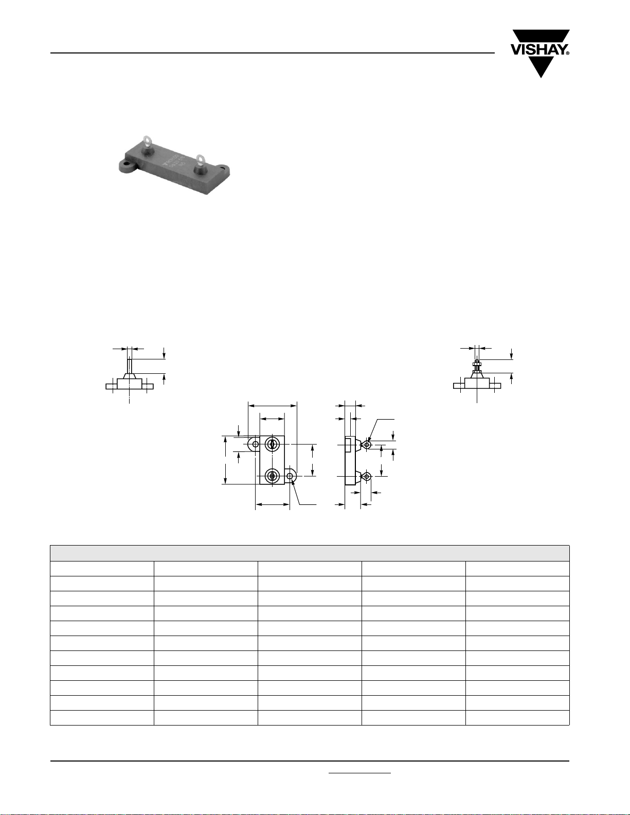
Power Resistors, for Mounting onto a Heatsink
Thick Film Technology
Manufactured in cermet thick film technology, these power
resistors exhibit remarkable characteristics and the series
includes 4 types ranging from 5 W to 50 W.
Designed to be mounted onto a heatsink, the resistors can
bear high short time overloads and 3 types of terminations
are available.
The resistors are non inductive and are particularly suitable
for high frequency operation and cut-out circuits.
DIMENSIONS in millimeters
FEATURES
• 5 W to 50 W
• High power rating
• High overload capabilities up to 2500 V
• Wide resistance range from 0R24 to 1 MΩ
• High thermal capacity up to 0.8 °C/W
• Easy mounting
• Reduced size and weight
• High insulation: 10
6
MΩ
RMS
RCH...R
Ø 2
General tolerance: ± 0.3 mm
6
RCH...S
H
W
S
L
T
F
Ø D
6
3
Ø 2.1
4.8
P
6
9
RCH...V
M2
6
DIMENSIONS
MODEL RCH 5 RCH 10 RCH 25 RCH 50
L 16.6 19 28 47.8
W 9111415.5
H 16.4 20.6 27.5 29.4
P Leads Pitch 10.2 12.7 18.3 30.5
F Connections Pitch 11.3 14.3 18.3 39.7
T 12.5 15.9 19.8 21.4
S 5.3 5 7.7 8
Ø D 2.4 2.4 3.2 3.2
V Leads M2 M2 M3 M3
Weight (g) 4 5 7 12
www.vishay.com For technical questions, contact: sfer@vishay.com
1 Revision: 09-Jun-08
Document Number: 50006
Page 3
RCH
Power Resistors, for Mounting onto a Heatsink
Vishay Sfernice
Thick Film Technology
MECHANICAL SPECIFICATIONS
Mechanical Protection Insulated case
Substrate Alumina
Resistive Element Cermet
Connections Tinned copper alloy
ENVIRONMENTAL SPECIFICATIONS
Temperature Range - 55 °C to + 125 °C
Climatic Category 55/125/56
PERFORMANCE
TESTS CONDITIONS TYPICAL DRIFTS
NF EN 140 000 CEI 115_1
Momentary Overload
Rapid Temperature Change
Load Life
Humidity (Steady State)
NF EN 140 000 125 °C CEI 68215 Test Na
NF EN 140 000 CEI 115_1
MIL STD 202 Method 103 B and C
2 P
< 2 UL
U
s
5 cycles
- 55 °C to + 125 °C
1000 h P
r
56 days RH 95 %
ELECTRICAL SPECIFICATIONS
Resistance Range
Standard Resistance Tolerances
Power Rating:
Chassis Mounted
Unmounted
Temperature Coeffi cient
Insulation Resistance
Total Inductance
/5 s
r
at + 25 °C
< ± (0.25 % + 0.05 Ω)
< ± (0.25 % + 0.05 Ω)
< ± (0.5 % + 0.05 Ω)
< ± (0.5 % + 0.05 Ω)
0.24 Ω to 1 MΩ E24 series
± 1 %, ± 2 %, ± 5 %, ± 10 %
± 150 ppm/°C (R > 1 Ω)
5 W to 50 W
2 W to 5.5 W
106 M
Ω
≤
0.1 µH
RESISTANCE VALUE IN RELATION TO TOLERANCE AND TCR
Resistance Value < 1 Ω > 1 Ω
Standard
Tolerances
Standard TCR ± 250 ppm/°C ± 150 ppm/°C
Tolerance on Request ± 1 % to ± 2 %
± 5 %
± 10 %
SPECIAL FEATURES
MODEL RCH 5 RCH 10 RCH 25 RCH 50
Power Rating-Chassis Mounted 5 W 10 W 25 W 50 W
Power Rating-Unmounted 2 W 2.5 W 4 W 5.5 W
Thermal Resistance R
Limiting Element Voltage (V
Max. Overload Voltage (V
Dielectric Strength (V
MIL STD 202 Method 301 10 mA Max.
Critical Resistance 5120 Ω 6250 Ω 12 100 Ω 33 024 Ω
Document Number: 50006 For technical questions, contact: sfer@vishay.com
Revision: 09-Jun-08 2
(j-c) 4.8 °C/W 3.2 °C/W 1.4 °C/W 0.8 °C/W
TH
) 160 V 250 V 550 V 1285 V
RMS
) 320 V 500 V 1100 V 2500 V
RMS
) 50 Hz, 1 Min
RMS
2000 V 2000 V 3500 V 3500 V
www.vishay.com
Page 4

RCH
Vishay Sfernice
Power Resistors, for Mounting onto a Heatsink
Thick Film Technology
RECOMMENDATIONS FOR MOUNTING ONTO A HEATSINK
Surfaces in contact must be carefully cleaned.
The heatsink must have an acceptable flatness: from 0.05 mm to 0.1 mm/100 mm.
Roughness of the heatsink must be around 6.3 µm. In order to improve thermal conductivity, surfaces in contact (alumina,
heat-sink) are coated with a silicone grease (type Sl 340 from Rhône-Poulenc or Dow 340 from Dow Corning).
The fastening of the resistor to the heatsink is under pressure control of two screws (not supplied).
Tightening Torque
on heatsink
In order to improve the dissipation, either forced-air cooling or liquid cooling may be used.
A low thermal radiation of the case allows several resistors to be mounted onto the same heatsink.
Do not forget to respect an insulation value between two resistors (dielectric strength in dry air 1 kV/mm).
In any case the hot spot temperature, measured locally on the case must not exceed 125 °C.
Tests should be performed by the user.
CHOICE OF THE HEATSINK
The user must choose the heatsink according to working conditions of the component (power, room temperature). Maximum
working temperature must not exceed 125 °C. The dissipated power is simply calculated by the following ratio:
RCH 5 RCH 10 RCH 25 RCH 50
0.5 Nm 0.6 Nm 0.7 Nm 1 Nm
--------------------------------------------------------------- ---=
P
R
ΔT
jc–()RTHca–()+[]
TH
1()
P: Expressed in W
T: Difference between maximum working temperature and room temperature.
: (j-c): Thermal resistance value measured between resistance layer and outer side of the resistor.
R
TH
It is the thermal resistance of the component (See Special Features table).
: (c-a): Thermal resistance value measured between outer side of the resistor and room temperature.
R
TH
It is the thermal resistance of the heatsink depending on the heatsink itself (type, shape) and the quality of the
fastening device.
Example:
: (c-a) for RCH 25 power rating 20 W at ambient temperature + 50 °C.
R
TH
ΔT ≤ 125 °C - 50 °C ≤ 75 °C
(j-c) = 1.4 °C/W (Special Features)
R
TH
(j-c) + RTH (c-a) = = = 3.75 °C/W
R
TH
(c-a) ≤ 3.75 °C/W - 1.4 °C/W ≤ 2.35 °C/W
R
TH
ΔT
------P
75
-----20
www.vishay.com For technical questions, contact: sfer@vishay.com
3 Revision: 09-Jun-08
Document Number: 50006
Page 5

RCH
Power Resistors, for Mounting onto a Heatsink
Vishay Sfernice
Thick Film Technology
OVERLOADS
The applied voltage must always be lower than the maximum overload voltage as shown in the special features table.
The values indicated on the graph below are applicable to resistors in air or mounted onto a heatsink.
ENERGY CURVE
1000
100
RCH 50
RCH 25
RCH 10
RCH 5
- 1
10
POWER RATING CHART
10
1
0.1
ENERGY IN JOULES
- 6
10
- 5
10
- 4
10
- 3
10
10
OVERLOAD DURATION IN s
- 2
For resistors mounted onto heatsink and thermal resistance of 1 °C/W.
To improve the thermal conductivity, surfaces in contact should be coated with a silicone grease.
100
RCH 10
75
50
RCH 50
RCH 25
RCH 5
% RATED POWER
25
0
0
20 40 60 80 100 120 140
AMBIENT TEMPERATURE IN °C
MARKING
Model, Style, Resistance Value (in Ω), Tolerance (in %), Manufacturing Date, VISHAY trade mark.
ORDERING INFORMATION
RCH 25 3.3 kΩ ± 5 % R XXX
MODEL STYLE RESISTANCE VALUE TOLERANCE
CONNECTIONS
CUSTOM DESIGN
Optional
± 1 %
± 2 %
± 5 %
Optional
S: Flat with hole
R: Round lead
V: M2 screw
Optional
± 10 %
Document Number: 50006 For technical questions, contact: sfer@vishay.com
www.vishay.com
Revision: 09-Jun-08 4
Page 6

RCH
Vishay Sfernice
Power Resistors, for Mounting onto a Heatsink
GLOBAL PART NUMBER INFORMATION
10S3300 J 0C HR 0S6
GLOBAL
MODEL
RCH 05
SIZE LEADS OHMIC VALUE TOLERANCE PACKAGING SPECIAL
R = Round lead
10
25
50
V = M2 screw
S = Flat with hole
Thick Film Technology
The firts four digits are
significant figures and the
last digit specifies the
number of zeros to follow.
R designates decimal point.
4R700 = 4.7 Ω
48701 = 48 700 Ω
33000 = 33 000 Ω
R0100 = 0.01 Ω
R6800 = 0.68 Ω
27000 = 2700 Ω = 2K7 Ω
F = 1 %
G = 2 %
J = 5 %
K = 10 %
S06 = Bag
25 pieces
As applicable
Ex = XXX
www.vishay.com For technical questions, contact: sfer@vishay.com
5 Revision: 09-Jun-08
Document Number: 50006
Page 7

Legal Disclaimer Notice
Vishay
Disclaimer
All product specifications and data are subject to change without notice.
Vishay Intertechnology, Inc., its affiliates, agents, and employees, and all persons acting on its or their behalf
(collectively, “Vishay”), disclaim any and all liability for any errors, inaccuracies or incompleteness contained herein
or in any other disclosure relating to any product.
Vishay disclaims any and all liability arising out of the use or application of any product described herein or of any
information provided herein to the maximum extent permitted by law. The product specifications do not expand or
otherwise modify Vishay’s terms and conditions of purchase, including but not limited to the warranty expressed
therein, which apply to these products.
No license, express or implied, by estoppel or otherwise, to any intellectual property rights is granted by this
document or by any conduct of Vishay.
The products shown herein are not designed for use in medical, life-saving, or life-sustaining applications unless
otherwise expressly indicated. Customers using or selling Vishay products not expressly indicated for use in such
applications do so entirely at their own risk and agree to fully indemnify Vishay for any damages arising or resulting
from such use or sale. Please contact authorized Vishay personnel to obtain written terms and conditions regarding
products designed for such applications.
Product names and markings noted herein may be trademarks of their respective owners.
Document Number: 91000 www.vishay.com
Revision: 18-Jul-08 1
 Loading...