

Page 1

6121 Baker Road,
Suite 108
Minnetonka, MN 55345
www.chtechnology.com
Phone (952) 933-6190
Fax (952) 933-6223
1-800-274-4284
Thank you for downloading this document from C&H Technology, Inc.
Please contact the C&H Technology team for the following questions -
Technical
Application
Assembly
Availability
Pricing
Phone – 1-800-274-4284
E-Mail – sales@chtechnology.com
www.chtechnology.com - SPECIALISTS IN POWER ELECTRONIC COMPONENTS AND ASSEMBLIES - www.chtechnology.com
Page 2
www.vishay.com
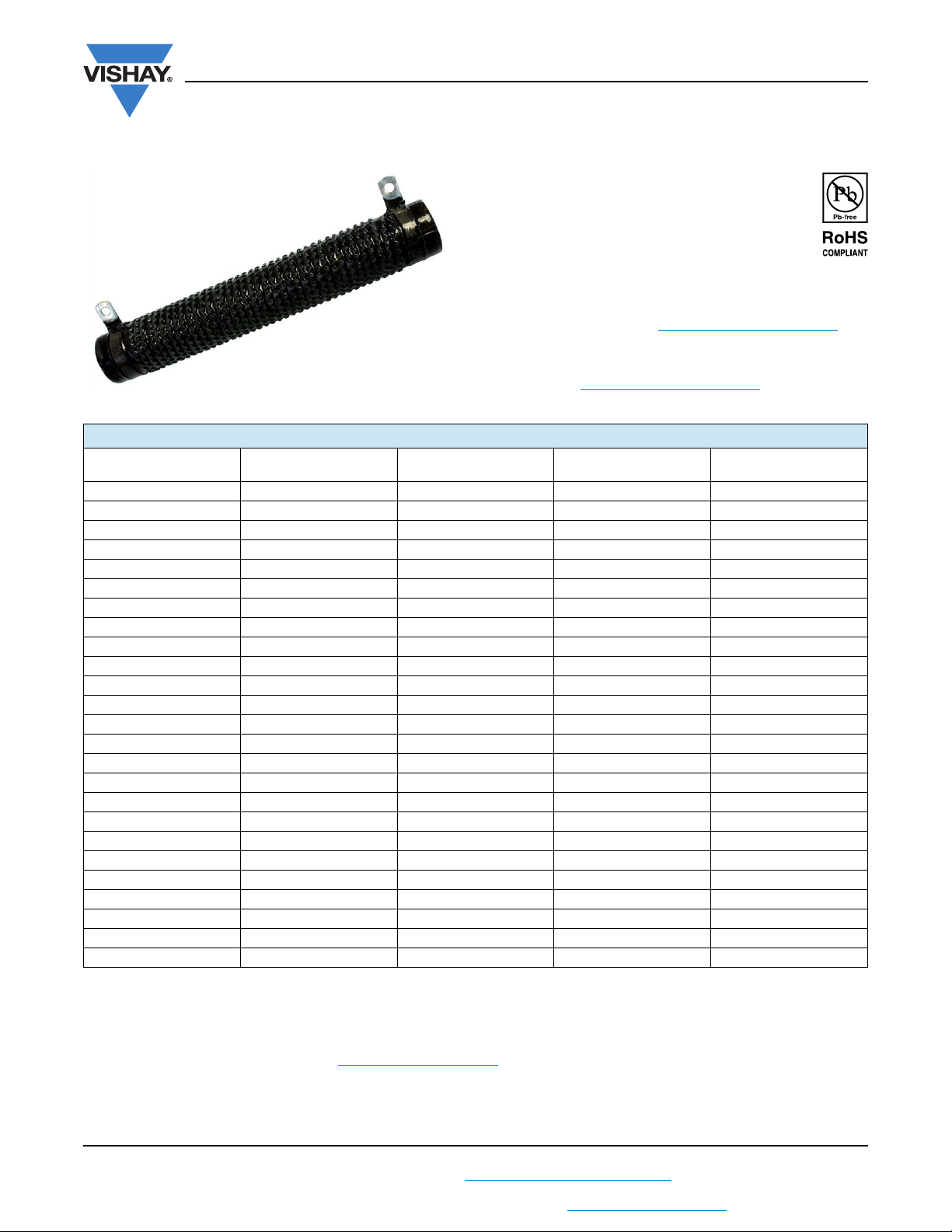
Fixed Ribwound Resistor
FEATURES
• Resistance wire is spotwelded to the terminal
bands and then “locked” onto the core with a
vitreous enamel or silicone coating
• Hardware can be supplied mounted, as loose
assemblies, or as individual parts. Enclosures
can also be produced.
• Available as fixed and adjustable resistors (for adjustable
Ribwound Resistor see www.vishay.com/doc?31809
•Wirewound
• Material categorization: For definitions of compliance
please see www.vishay.com/doc?99912
STANDARD ELECTRICAL SPECIFICATIONS
GLOBAL MODEL HISTORICAL MODEL
RBEF0040
RBEF0050
RBEF0075
RBEF0090
RBEF0100
RBEF0110
RBEF0120
RBEF0135
RBEF0150
RBEF0160
RBEF0175
RBEF0180
RBEF0220
RBEF0225
RBEF0240
RBEF0300
RBEF0375
RBEF0400
RBEF0420
RBEF0500
RBEF0550
RBSF0750
RBSF1000
RBSF1500
RBSF2000
(1)
(1)
(1)
(1)
(1)
(1)
(1)
(1)
(1)
(1)
(1)
(1)
(1)
(1)
(1)
(1)(3)
(1)
(1)
(1)
(1)(3)
(1)
(2)
(2)(3)
(2)(3)
(2)
9-32-R 40 0.010 to 10.6 10
12-32-R 50 0.020 to 8.2 10
12-48-R 75 0.010 to 19.3 10
9-64-R 90 0.015 to 28.3 10
12-56-R 100 0.012 to 24.5 10
12-64-R 110 0.015 to 30.6 10
12-72-R 120 0.018 to 36.8 10
12-80-R 135 0.021 to 42.9 10
18-64-R 150 0.019 to 44.8 10
12-96-R 160 0.027 to 55.0 10
18-72-R 175 0.023 to 53.7 10
12-104-R 180 0.030 to 61.3 10
18-96-R 220 0.035 to 80.6 10
18-98-R 225 0.036 to 82.8 10
18-104-R 240 0.038 to 89.5 10
18-136-R 300 0.054 to 125 10
18-168-R 375 0.069 to 161 10
18-180-R 400 0.075 to 175 10
18-188-R 420 0.079 to 184 10
26-168-R 500 0.081 to 210 10
26-188-R 550 0.093 to 242 10
40-192-R 750 0.128 to 166 10
40-240-R 1000 0.168 to 217 10
40-320-R 1500 0.234 to 303 10
52-320-R 2000 0.281 to 391 10
Notes
• Ratings are based on a temperature rise of 375 °C above an ambient of 40 °C.
• Operating temperature range - 55 °C to 415 °C.
(1)
RBEF0040 to RBEF0550 vitreous enamel coating is standard, silicone coating is available.
(2)
RBSF0750 to RBSF2000 silicone coating is standard.
(3)
Stock wattage, see Ribwound Stock Ribs (www.vishay.com/doc?31808)
(4)
Closer tolerances available upon request.
POWER RATING
W
RB Series Fixed
RESISTANCE RANGE
Vishay Milwaukee
)
TOLERANCE
(4)
%
Revision: 10-Jan-13
1
Document Number: 31807
For technical questions, contact: vishaymilwaukeeresistor@vishay.com
THIS DOCUMENT IS SUBJECT TO CHANGE WITHOUT NOTICE. THE PRODUCTS DESCRIBED HEREIN AND THIS DOCUMENT
ARE SUBJECT TO SPECIFIC DISCLAIMERS, SET FORTH AT www.vishay.com/doc?91000
Page 3
D
Type H
B
A
C
B
D
C
A
Type D, F, G
RB Series Fixed
www.vishay.com
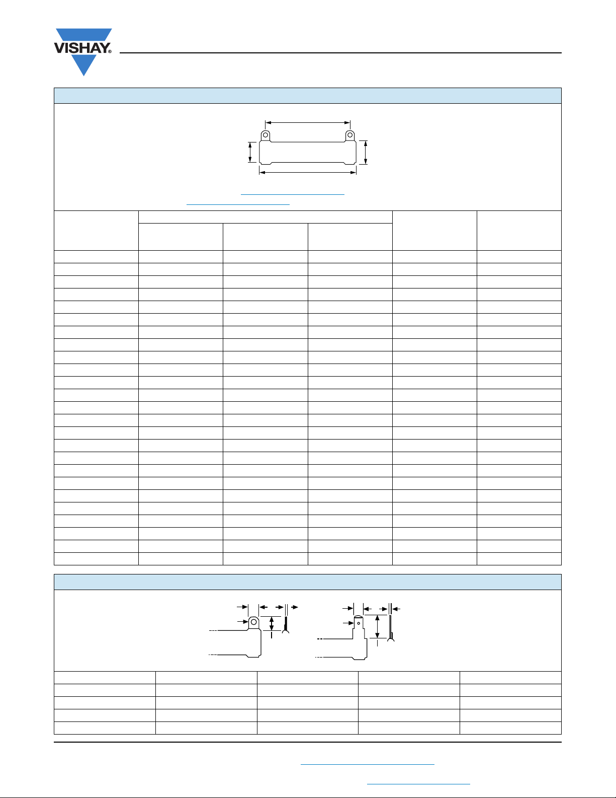
DIMENSIONS in inches (millimeters)
A
D C
B
• For Terminal Data and Mounting Hardware, see www.vishay.com/doc?31811
• For Enclosures and Frames, see www.vishay.com/doc?31810
GLOBAL
MODEL
RBEF0040 2 (50.8) 0.5625 (14.2875) 0.3125 (7.9375) 1.25 (31.75) D
RBEF0050 2 (50.8) 0.75 (19.05) 0.5 (12.7) 1.15 (29.21) F
RBEF0075 3 (76.2) 0.75 (19.05) 0.5 (12.7) 2.13 (53.975) F
RBEF0090 4 (101.6) 0.5625 (14.2875) 0.3125 (7.9375) 3.50 (88.9) D
RBEF0100 3.5 (88.9) 0.75 (19.05) 0.5 (12.7) 2.63 (66.675) F
RBEF0110 4 (101.6) 0.75 (19.05) 0.5 (12.7) 3.13 (79.375) F
RBEF0120 4.5 (114.3) 0.75 (19.05) 0.5 (12.7) 3.63 (92.075) F
RBEF0135 5 (127) 0.75 (19.05) 0.5 (12.7) 4.13 (104.775) F
RBEF0150 4 (101.6) 1.125 (28.575) 0.75 (19.05) 3.13 (79.375) F
RBEF0160 6 (152.4) 0.75 (19.05) 0.5 (12.7) 5.13 (130.175) F
RBEF0175 4.5 (114.3) 1.125 (28.575) 0.75 (19.05) 3.63 (92.075) F
RBEF0180 6.5 (165.1) 0.75 (19.05) 0.5 (12.7) 5.63 (142.875) F
RBEF0220 6 (152.4) 1.125 (28.575) 0.75 (19.05) 5.13 (130.175) F
RBEF0225 6.125 (155.575) 1.125 (28.575) 0.75 (19.05) 5.25 (133.35) F
RBEF0240 6.5 (165.1) 1.125 (28.575) 0.75 (19.05) 5.63 (142.875) F
RBEF0300 8.5 (215.9) 1.125 (28.575) 0.75 (19.05) 7.63 (193.675) F
RBEF0375 10.5 (266.7) 1.125 (28.575) 0.75 (19.05) 9.63 (244.475) F
RBEF0400 11.25 (285.75) 1.125 (28.575) 0.75 (19.05) 10.50 (266.7) F
RBEF0420 11.75 (298.45) 1.125 (28.575) 0.75 (19.05) 10.88 (276.225) F
RBEF0500 10.5 (266.7) 1.625 (41.275) 1.125 (28.575) 9.00 (228.6) G
RBEF0550 11.75 (298.45) 1.625 (41.275) 1.125 (28.575) 10.25 (260.35) G
RBSF0750 12 (304.8) 2.5 (63.5) 1.75 (44.45) 10.50 (266.7) G
RBSF1000 15 (381) 2.5 (63.5) 1.75 (44.45) 13.50 (342.9) G
RBSF1500 20 (508) 2.5 (63.5) 1.75 (44.45) 18.50 (169.9) G
RBSF2000 20 (508) 3.25 (82.55) 1.75 (44.45) 18.50 (169.9) G
B
LENGTH
CORE DIMENSIONS (REF.) A
C
OUTER DIAMETERDINNER DIAMETER
DISTANCE
BETWEEN
TERMINAL (REF.)
Vishay Milwaukee
TERMINAL STYLE
TERMINAL STYLE in inches (millimeters)
DIMENSIONS D (1/4" LUG) F (3/8" LUG) G (1/2" LUG) H (1/4" SQC)
Width (A) 0.25 (6.35) 0.375 (9.525) 0.5 (12.7) 0.25 (6.35)
Height (B) 0.5 (12.7) 0.625 (15.875) 0.9375 (23.8125) 0.625 (15.875)
Dia. (C) 0.17 (4.318) 0.2 (5.08) 0.26 (6.604) 0.065 (1.651)
Thickness (D) 0.02 (0.508) 0.035 (0.889) 0.046 (1.1684) 0.032 (0.8128)
Revision: 10-Jan-13
THIS DOCUMENT IS SUBJECT TO CHANGE WITHOUT NOTICE. THE PRODUCTS DESCRIBED HEREIN AND THIS DOCUMENT
For technical questions, contact: vishaymilwaukeeresistor@vishay.com
ARE SUBJECT TO SPECIFIC DISCLAIMERS, SET FORTH AT www.vishay.com/doc?91000
2
Document Number: 31807
Page 4
RB Series Fixed
www.vishay.com
MATERIAL SPECIFICATIONS
Element Copper-nickel, nickel-chrome, iron-chrome-aluminum
Core Cordierite, steatite
Coating Special high temperature silicone or vitreous enamel
Standard terminals Nickel-iron
Part marking Value, date code, MRC
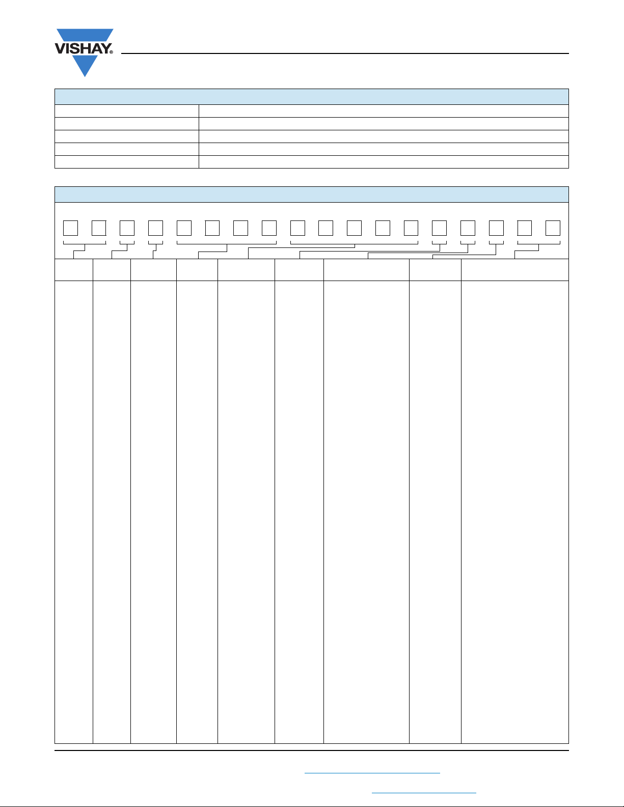
GLOBAL PART NUMBER INFORMATION
Global Part Numbering example: RBSF150015R00JGBNI (RBSF1500-NI 15 5 % 1/2L B)
RBSF150015R00JGBNI
Vishay Milwaukee
MODEL
(2 digits)
RB E
COATING
(1 digit)
=
Enamel
S
=
Silicone
TYPE
(1 digit)
F
= Fixed
SIZE
(4 digits)
0300 =
300 W
2000 =
2000 W
VALUE
(5 digits)
R
= Decimal
K
= Thousand
R1500
= 0.15
1K500
= 1.5 k
Check
datasheet for
available value
range
TOLERANCE
(1 digit)
D = ± 0.5 %
F = ± 1.0 %
G = ± 2.0 %
H = ± 3.0 %
J = ± 5.0 %
K = ± 10 %
M = ± 20 %
TERMINAL
(1 digit)
D
= 1/4" lug
E
= 5/16" lug
F
= 3/8" lug
G
= 1/2" lug
H
= 1/4" single
quick-connect
J
= 1/4" double
quick-connect
K
= 1/4" lug with steel
hardware (ES-707F)
L
= 5/16" lug with steel
hardware (ES-707F)
M
= 3/8" lug with steel
hardware (ES-707F)
N
= 3/8" lug with brass
hardware (ES-707b)
O
= 1/2" lug with steel
hardware (ES-707F)
P
= 1/2" lug with brass
hardware (ES-707b)
Q
= 1/4" lug with steel
hardware (ES-708F)
R
= 5/16" lug with steel
hardware (ES-708F)
S
= 3/8" lug with steel
hardware (ES-708F)
T
= 3/8" lug with brass
hardware (ES-708b)
U
= 1/2" lug with steel
hardware (ES-708F)
V
= 1/2" lug with brass
hardware (ES-708b)
W
= Ferrule
PACKAGING
(1 digit)
B = Bulk
See
packaging
codes for
additional
options
SPECIAL
(2 digits)
00 = Standard
01 = Standard with
customer part no. stamp
NI = Non-inductive
CT = Center tap
SW = Surge winding
LT = Low temperature
coefficient alloy
EC = End caps
CP = Push in clips (bulk)
CA = Push in clips
(assembled)
VT = Vertical mount
VS = VT with customer
part no. stamp
ES = End slot side slot
bracket
1A = 1 high bracket zinc
plated steel
1S = 1A with customer part
no. stamp
1B = 1 high bracket
stainless steel (300 W only)
1C = Live bracket
2A = 2 high bracket zinc
plated steel
2B = 2 high bracket
stainless steel (300 W only)
3A = 3 high bracket zinc
plated steel
3B = 3 high bracket
stainless steel (300 W only)
4A = 4 high bracket zinc
plated steel
4B = 4 high bracket
stainless steel (300 W only)
Note
2A, 2B, 3A, 3B, 4A, and 4B
assemblies:
include identical resistors
only wiring to be supplied
by customer
reference CS series for further
customization
Note
3A, 3B, 4A, and 4B
limitations:
brackets fit 40 W to 550 W RB
resistors
Revision: 10-Jan-13
For technical questions, contact: vishaymilwaukeeresistor@vishay.com
THIS DOCUMENT IS SUBJECT TO CHANGE WITHOUT NOTICE. THE PRODUCTS DESCRIBED HEREIN AND THIS DOCUMENT
ARE SUBJECT TO SPECIFIC DISCLAIMERS, SET FORTH AT www.vishay.com/doc?91000
3
Document Number: 31807
Page 5

Legal Disclaimer Notice
www.vishay.com
Vishay
Disclaimer
ALL PRODUCT, PRODUCT SPECIFICATIONS AND DATA ARE SUBJECT TO CHANGE WITHOUT NOTICE TO IMPROVE
RELIABILITY, FUNCTION OR DESIGN OR OTHERWISE.
Vishay Intertechnology, Inc., its affiliates, agents, and employees, and all persons acting on its or their behalf (collectively,
“Vishay”), disclaim any and all liability for any errors, inaccuracies or incompleteness contained in any datasheet or in any other
disclosure relating to any product.
Vishay makes no warranty, representation or guarantee regarding the suitability of the products for any particular purpose or
the continuing production of any product. To the maximum extent permitted by applicable law, Vishay disclaims (i) any and all
liability arising out of the application or use of any product, (ii) any and all liability, including without limitation special,
consequential or incidental damages, and (iii) any and all implied warranties, including warranties of fitness for particular
purpose, non-infringement and merchantability.
Statements regarding the suitability of products for certain types of applications are based on Vishay’s knowledge of typical
requirements that are often placed on Vishay products in generic applications. Such statements are not binding statements
about the suitability of products for a particular application. It is the customer’s responsibility to validate that a particular
product with the properties described in the product specification is suitable for use in a particular application. Parameters
provided in datasheets and/or specifications may vary in different applications and performance may vary over time. All
operating parameters, including typical parameters, must be validated for each customer application by the customer’s
technical experts. Product specifications do not expand or otherwise modify Vishay’s terms and conditions of purchase,
including but not limited to the warranty expressed therein.
Except as expressly indicated in writing, Vishay products are not designed for use in medical, life-saving, or life-sustaining
applications or for any other application in which the failure of the Vishay product could result in personal injury or death.
Customers using or selling Vishay products not expressly indicated for use in such applications do so at their own risk. Please
contact authorized Vishay personnel to obtain written terms and conditions regarding products designed for such applications.
No license, express or implied, by estoppel or otherwise, to any intellectual property rights is granted by this document or by
any conduct of Vishay. Product names and markings noted herein may be trademarks of their respective owners.
Material Category Policy
Vishay Intertechnology, Inc. hereby certifies that all its products that are identified as RoHS-Compliant fulfill the
definitions and restrictions defined under Directive 2011/65/EU of The European Parliament and of the Council
of June 8, 2011 on the restriction of the use of certain hazardous substances in electrical and electronic equipment
(EEE) - recast, unless otherwise specified as non-compliant.
Please note that some Vishay documentation may still make reference to RoHS Directive 2002/95/EC. We confirm that
all the products identified as being compliant to Directive 2002/95/EC conform to Directive 2011/65/EU.
Vishay Intertechnology, Inc. hereby certifies that all its products that are identified as Halogen-Free follow Halogen-Free
requirements as per JEDEC JS709A standards. Please note that some Vishay documentation may still make reference
to the IEC 61249-2-21 definition. We confirm that all the products identified as being compliant to IEC 61249-2-21
conform to JEDEC JS709A standards.
Revision: 02-Oct-12
1
Document Number: 91000
 Loading...