

Page 1

6121 Baker Road,
Suite 108
Minnetonka, MN 55345
www.chtechnology.com
Phone (952) 933-6190
Fax (952) 933-6223
1-800-274-4284
Thank you for downloading this document from C&H Technology, Inc.
Please contact the C&H Technology team for the following questions -
Technical
Application
Assembly
Availability
Pricing
Phone – 1-800-274-4284
E-Mail – sales@chtechnology.com
www.chtechnology.com - SPECIALISTS IN POWER ELECTRONIC COMPONENTS AND ASSEMBLIES - www.chtechnology.com
Page 2
RA
Vishay Sfernice
Adjustable Wirewound Enamelled Resistors
FEATURES
• 21 Watt to 180 Watt at 25°C
• NF C 93-214
- RBA 13 x 70
- RBA 20 x 117
- RBA 25 x 168
”B” Ring
The ceramic tubular core ensures high dissipation capacity and excellent resistance to thermal shock and overload. The resistor
winding is evenly coiled on the core and protected by an enamel coating. A longitudinal opening provides for one or more
electrical connections by means of sliding collars equipped with a tongued connector.
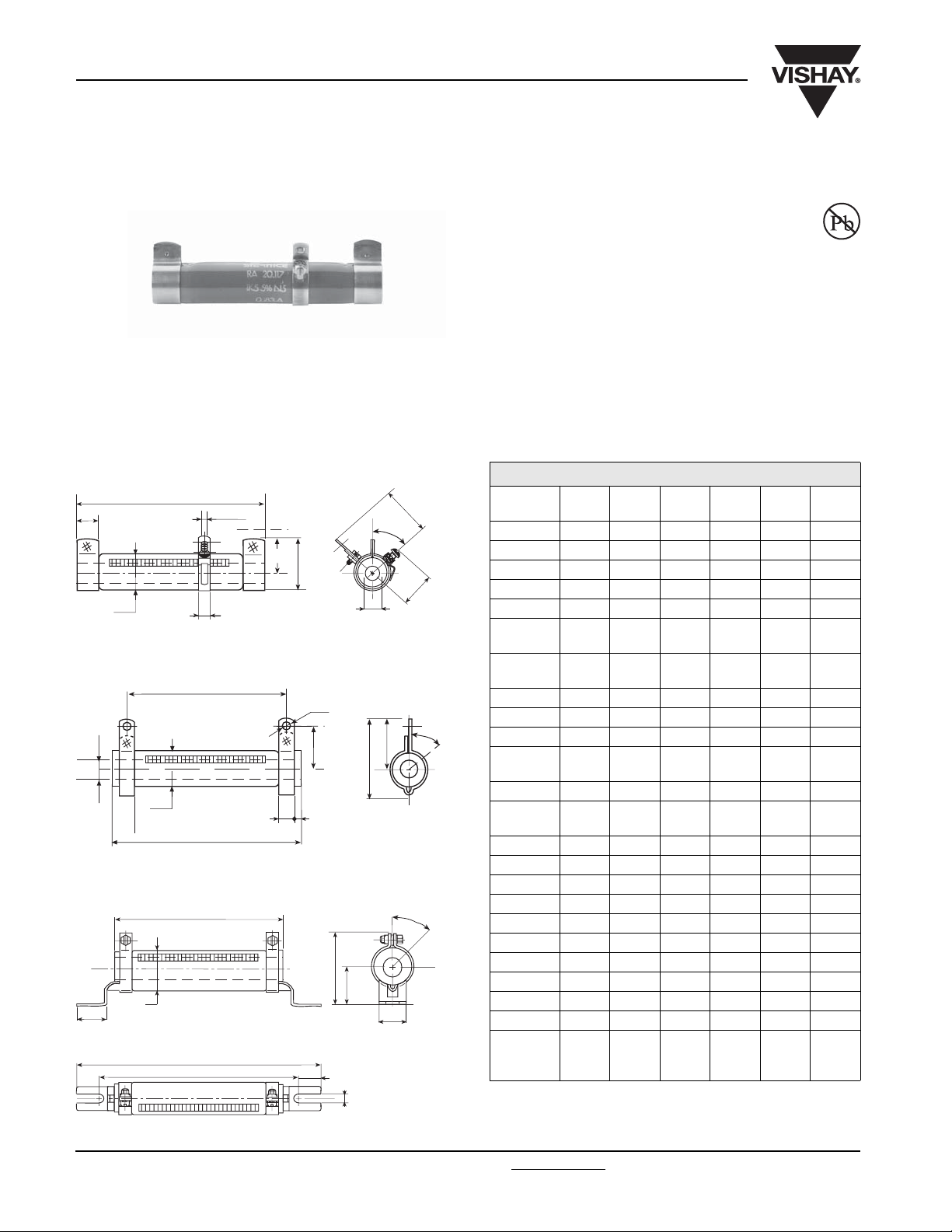
DIMENSIONS in millimeters
WELDED STAINLESS STEEL 304 L BAND “B”
DIMENSIONS in millimeters
A
F
ØB
Ø4.2
D
O
E
ØC
K
4
5
°
J
WELDED STAINLESS STEEL 304 L COLLAR “AN” TYPE 1
M
ØS
ØC
ØB
V
ZT
A
X
4
R
SCREWED STAINLESS STEEL 304 L “CS” TYPE 1
A
P
26
ØB
L
N
H
15
U
4
5
°
Q
5
°
RA
MODEL
13 x 70 16 x 94 20 x 117 25 x 138 25 x 168 30 x 250
Connection AN-B* AN-B AN-B AN-B-CS AN-B-CS AN-B-CS
A ± 2 70 94 117 138 168 250
Ø B max. 16 19.5 23 28 28 33
Ø C min. 5 9 9 12 12 17
D 16 ± 0.5 17.5 ± 0.5 21 ± 0.7 23.5 ± 1 23.5 ± 1 26 ± 1
E + 0.5
+ 0
F + 0.5
+ 0
788888
10.5 12 14 15 15 18
H ± 1 - - - 27 27 30
J max 19.523 2527.527.530
K max 24 29.5 31.5 34 34 36.5
L - 0
- 4
- - - 199 229 317
M 56 ± 2 78 ± 2 98 ± 2 117 ± 2 147 ± 2 227 ± 2.5
N - 0
- 4
- - - 169 199 287
O max 24.5 28 33 38.5 38.5 43.5
P ± 1.5 – – – 50 50 60
Q ± 0.5 – – – 24 24 25
R 24 ± 0.5 26.5 ± 0.5 31 ± 0.7 33.5 ± 1 33.5 ± 1 36 ± 1
S 4.2 4.2 4.2 5.7 5.7 5.7
T 6.35 6.35 6.35 9 9 13
U ± 0.5 –––6.56.59
V 20 ± 0.5 21 ± 0.5 24 ± 0.7 28.5 ± 1 28.5 ± 1 33 ± 1
X 34.5 ± 1 38 ± 1 42 ± 1 51 ± 1.5 51 ± 1.5 55 ± 1.5
Z approx 3.5 56665
Average
unit
40 70 116 200 225 415
weight in g
* Also with CS and CR collars. See RW data sheet.
www.vishay.com For technical questions, contact: sfer@vishay.com Document Number: 50019
67 Revision: 21-Jun-06
Page 3

RA
Adjustable Wirewound Enamelled Resistors
Vishay Sfernice
MECHANICAL SPECIFICATIONS
Mechanical Protection vitreous enamel
Resistive Element Ni-Cr wire
Connections B band
AN or CS collar
Average Unit Weight 40 to 415g
ENVIRONMENTAL SPECIFICATIONS
Temperature Limits - 55 °C + 350 °C
Climatic Category - 55 °C/+ 200 °C/56 days
ELECTRICAL SPECIFICATIONS
Resistance Range 33 to 22K
(E6 series)
Tol erance
Standard ± 10 %
Power Rating 21 W to 180 W at 25 °C
Temperature Coeffi cient + 75 ppm/°C (typical)
PERFORMANCE
TESTS CONDITIONS REQUIREMENTS TYPICAL VALUES AND DRIFTS
Short Time Overload 10 Pr 5 s
Climatic sequence - 55 °C + 200 °C
Humidity
(Steady State)
Thermal Shock Load at Pr
Resistor Strength 200N ± 10N 2 % or 0.05 0.25
Vibration 55/10 1 %* or 0.05 0.5
Terminal Strength AN
Load Life 1000 hours at Pr
* 1 % of total resistance and 2 % between sliding collar and fixed connection.
B
followed by exposure at - 55°C/15
Voltage < 6000V
5 cycles
56 days
95 % R.H.
Traction 40 Ncm
Torque 60 Ncm
25 °C
90 /30
Insulation resistance > 100M
Insulation resistance > 100M
2
%
or 0.05 0.5
3 % or 0.05
2 % or 0.05
2 % or 0.05 0.5
1 % or 0.05 0.25 %
5
%
1.5 %
0.5
%
1
%
%
%
%
%
SPECIAL FEATURES
RA STYLE 13 x 70 16 x 94 20 x 117 25 x 138 25 x 168 30 x 250
Designation NF C 93-214 RBA 13 x 70 - RBA 20 x 117 - RBA 25 x 168 -
Power Rating NF C 93-214
at 25 °C
Maximum Power
Rating at 25 °C
Ohmic Range
(E6, E24 series)
13 W - 25 W - 50 W -
21 W 35 W 50 W 75 W 120 W 180 W
33 3.9K 68 3.9K 100 4.7K 150 6.8K 220 10K 330 22K
ADMISSIBLE RATED AMPERAGE
This must in all cases be less than:
PrW()
in
----------------Rn()
SLIDING COLLAR
Resistors are normally supplied with 1 sliding collar fi tted and locked in a specifi c position.
Additional collars can be supplied and adjusted at the factory to special order (on request).*
* Quote ohmic value and tolerance of each resistance section, and Rn value.
MAXIMUM ADDITIONAL COLLARS
MODEL
AND TYPE
Additional
sliding collar
Document Number: 50019 For technical questions, contact: sfer@vishay.com
Revision: 21-Jun-06 68
RA
13 x 70
111234
RA
16 x 94
RA
20 x 117
RA
25 x 138
RA
25 x 168
RA
30 x 250
www.vishay.com
Page 4

RA
Vishay Sfernice
POWER RATING CHART
TEMPERATURE RISE
Adjustable Wirewound Enamelled Resistors
100
75
50
% RATED POWER
25
0
0 50 100 150 200 250 300 350
AMBIENT TEMPERATURE IN DEGREES CELSIUS
400
300
A
R
RA 13 x 70
4
9
x
6
0 x
1
2
A
R
8
8
17
3
1
1
x
5
2
A
A
R
R
0
6
5
1
2
x
x
5
0
2
3
A
R
200
100
HOT SPOT TEMPERATURE IN ¡C
0
10 100 1000
RATED POWER IN WATTS
MARKING
SFERNICE trademark, model, style, NF style (if applicable) ohmic value (in Ω), tolerance (in %), manufacturing date.
ORDERING INFORMATION
RA 13 × 70 AN 470U ± 10 % 1 C. SUP. B010 e
MODEL STYLE SPECIAL
DESIGN
CONNECTIONS OHMIC
VAL U E
TOLERANCE ADDITIONAL
SLIDING
PACKING LEAD
COLLAR
In option Custom items are subject
to extra-charge and min. order.
Please see price list.
SAP PART NUMBERING GUIDELINES
RA 13 × 70 G 470R0 K B10
MODEL STYLE CONNECTIONS OHMIC VALUE TOLERANCE PACKING
(Pb)-FREE
www.vishay.com For technical questions, contact: sfer@vishay.com Document Number: 50019
69 Revision: 21-Jun-06
 Loading...