

Page 1

6121 Baker Road,
Suite 108
Minnetonka, MN 55345
www.chtechnology.com
Phone (952) 933-6190
Fax (952) 933-6223
1-800-274-4284
Thank you for downloading this document from C&H Technology, Inc.
Please contact the C&H Technology team for the following questions -
Technical
Application
Assembly
Availability
Pricing
Phone – 1-800-274-4284
E-Mail – sales@chtechnology.com
www.chtechnology.com - SPECIALISTS IN POWER ELECTRONIC COMPONENTS AND ASSEMBLIES - www.chtechnology.com
Page 2
(
R7S0
1200A
Powerex, Inc., 173 Pavilion Lane, Youngwood, Pennsylvania 15697 (724) 925-7272 General Purpose Rectifier
www.pwrx.com
2400 Volts
1200 Amperes Average
R7S0 1200A General Purpose Rectifier
1200 Amperes Average, 2400 Volts
R7S0 1200A
Ordering Information:
Select the complete eight digit module part number from the table below.
Example: R7S01812XX is a 1800V 1200 A General Purpose Rectifier
Type
R7S0 18
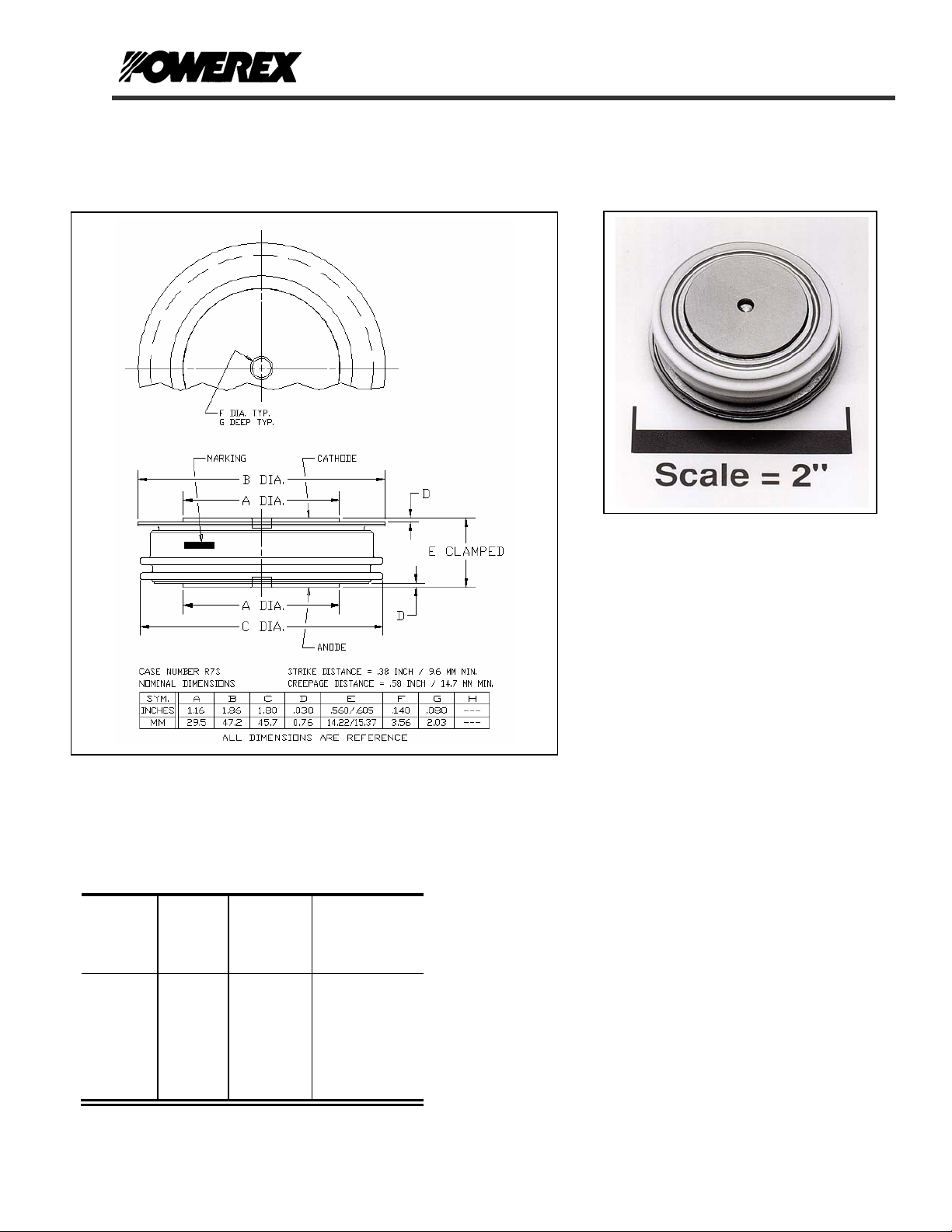
Outline Drawing)
Voltage Current
V
RRM
(Volts)
through
24
1800V
through
2400V
I
T(av)
(A)
12
1200A
Typical Recovery
Time
tRR
(µsec)
XX
10 µsec
typical
Description:
Powerex General Purpose
Rectifiers are designed for high
blocking voltage capability with low
forward voltage to minimize
conduction losses. The hermetic
Pow-R-Disc devices can be
mounted using commercially
available clamps and heatsinks.
Features:
Low Forward Voltage
Low Thermal Impedance
Low Profile Package
Hermetic Packaging
2
Excellent Surge and I
Applications:
Power Supplies
Motor Control
Free Wheeling Diode
Battery Chargers
Resistance Welding
t Ratings
Revision Date: 09/01/2006
Page 3

R7S0
1200A
+ 200V Volts
RRM
Revision Date: 09/01/2006
2
sec
Powerex, Inc., 173 Pavilion Lane, Youngwood, Pennsylvania 15697 (724) 925-7272 General Purpose Rectifier
www.pwrx.com
1200 Amperes Average
2400 Volts
Absolute Maximum Ratings
Characteristics Symbol Units
Non-Repetitive Transient Peak Reverse Blocking Voltage V
RMS Forward Current, TC = 86°C I
Average Current 180° Sine Wave, TC = 86°C I
RMS Forward Current, TC = 55°C I
Average Current 180° Sine Wave, TC = 86°C I
Peak One Cycle Surge Forward Current (Non-Repetitive) 60 Hz I
Peak One Cycle Surge Forward Current (Non-Repetitive) 50 Hz I
3 Cycle Surge Current I
10 Cycle Surge Current I
I2t (for Fusing) for One Cycle, 60 Hz I2t 337,500 A2 sec
Maximum I2t of Package (t = 8.3 msec) I2t 80 x 106 A
Operating Temperature TJ -65 to +175 °C
Storage Temperature T
Approximate Weight 4 oz.
113 g
Mounting Force 2000 to 2400 lb.
900 to 1090 kg.
V
RSM
1875 Amperes
F(RMS)
1200 Amperes
F(AV)
2355 Amperes
F(RMS)
1500 Amperes
F(AV)
9000 Amperes
FSM
8200 Amperes
FSM
6485 Amperes
FSM
5600 Amperes
FSM
-65 to +200 °C
stg
Page 4

Powerex, Inc., 173 Pavilion Lane, Youngwood, Pennsylvania 15697 (724) 925-7272 General Purpose Rectifier
www.pwrx.com
2400 Volts
1200 Amperes Average
Electrical Characteristics, TJ=25°C unless otherwise specified
Characteristics Symbol Test Conditions Min. Max. Units
Repetitive Peak Reverse Leakage Current I
Peak On-State Voltage VFM I
Threshold Voltage
Slope Resistance
VTM Coefficients, Full Range
Diode Reverse Recovery Time (Typical)
Thermal Characteristics
Maximum Thermal Resistance, Double Sided Cooling
Junction-to-Case
Case-to-Sink
T
RRM
V
(TO)
r
T
t
T
rr
=125°C, VR = V
J
=1500A, Duty Cycle < 0.1 % 1.60 V
FM
= 175°C, I = 15%I
T
J
TJ = 175°C, I = 15%I
50 mA
RRM
to I
F(AV)
F(AV)
0.831
FSM
to I
FSM
V
= A+ B Ln I +C I + D Sqrt I
FM
= 25°C, Ifm = 1500A,
C
/dt = -25A/µs, Tp = 190 µs
di
R
R
Θ(J-C)
R
Θ(C-S)
R7S0
1200A
A =
B =
C =
D =
10
Revision Date: 09/01/2006
0.441 V mΩ
1.585
-0.216
2.00 E-4
0.0308
s
µ
(Typical)
Max. Units
0.035
0.02
°C/W
°C/W
Page 5

Powerex, Inc., 173 Pavilion Lane, Youngwood, Pennsylvania 15697 (724) 925-7272 General Purpose Rectifier
www.pwrx.com
2400 Volts
5
4
3
2
1200 Amperes Average
Maximum On-State Forward Voltage Drop
( Tj = 175 °C )
Maximum Transient Thermal Impedance
.04000
.03000
.02000
R7S0
1200A
(Junction to Case)
1
On-State Voltage - Vtm - Volts
0
10 100 1000 10000
3000
2500
2000
1500
1000
500
Maximum Power Dissipation Per SCR - Wa tts
0
0 200 400 600 800 1000 1200 1400
3500
3000
2500
2000
1500
1000
500
Maximum Power Dissipation Per SCR - Watts
0
0 200 400 6 00 800 1000 1200 1400 1600 1800 2000
Instantaneous On-State Current - Itm - Amperes
Maximum On-State Power Dissipation
Maximum On-State Power Dissipation
15°
(Sinusoidal Waveform)
15°
30°
Average On-State Current - It(av) - Amperes
30°
Average On-State Current - It(av) - Amperes
60°
(Rectangular Waveform)
120°
90°
60°
120°
90°
180
0
CONDUCTION ANGLE
180°
0
CONDUCTION ANGLE
180
180°
360
270°
360°
360
.01000
Thermal Impedance - Rjc - °C/W
.00000
.00010 .00100 .01000 .10000 1.00000 10.00000 100.00000
Time - t - Seconds
Maximum Allowable Case Temperature
180
170
160
150
140
130
120
110
100
Max. Case Temperature - Tcase - °C
90
80
0 200 400 600 800 1000 1200 1400
(Sinusoidal Waveform)
180
0
CONDUCTION ANGLE
30°
Average On-State Current - It(av) - Amperes
60°
120°90°
360
180°
Maximum Allowable Case Temperature
(Rectangular Waveform)
180
170
160
150
140
130
120
110
100
90
80
Max. Case Temperature - Tcase - °C
70
60
50
0 200 400 600 800 1000 1200 1400 1600 1800 2000 2200
30°
15°
90°60°
120°
180
0
CONDUCTION ANGLE
180°
270°
360
360°C
Average On-State Current - It(av) - Amperes
Revision Date: 09/01/2006
 Loading...