

Page 1

6121 Baker Road,
Suite 108
Minnetonka, MN 55345
www.chtechnology.com
Phone (952) 933-6190
Fax (952) 933-6223
1-800-274-4284
Thank you for downloading this document from C&H Technology, Inc.
Please contact the C&H Technology team for the following questions -
Technical
Application
Assembly
Availability
Pricing
Phone – 1-800-274-4284
E-Mail – sales@chtechnology.com
www.chtechnology.com - SPECIALISTS IN POWER ELECTRONIC COMPONENTS AND ASSEMBLIES - www.chtechnology.com
Page 2
Powerex, Inc., 173 Pavilion Lane, Youngwood, Pennsylvania 15697-1800 (724) 925-7272 Fast Recovery Diode Module
www.pwrx.com
QR_0610T30
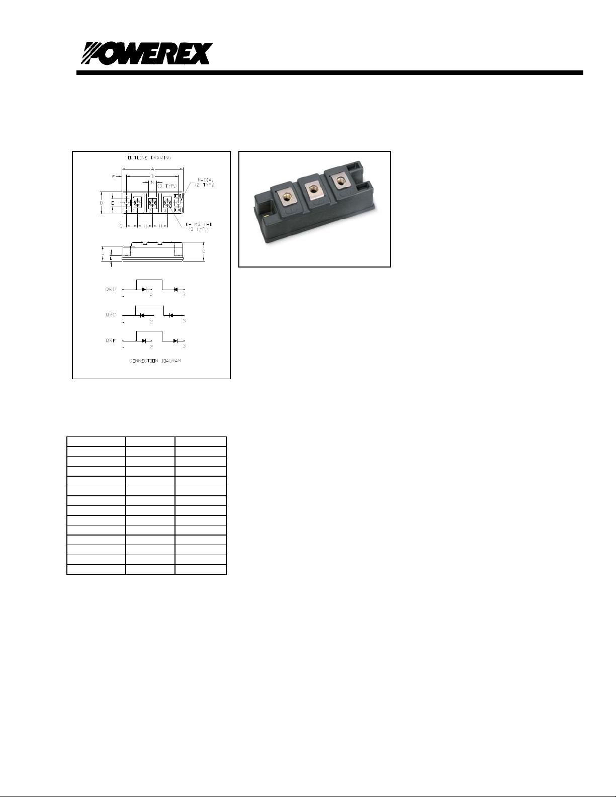
QR_0610T30
Fast Recovery Diode Module
Dimensions Inches Millimeters
A 3.70 94.0
B 1.34 34.0
C 1.18 30.0
D 3.15 80.0
E 0.50 12.7
F 0.28 7.0
G 0.67 17.0
H 0.91 23.0
J 0.91 23.0
K M6X1.0 M6X1.0
L 0.31 8.0
M 0.256 Dia. 6.5 Dia.
N 0.47 12.0
Description:
Powerex Fast Recovery Diode
Modules are designed for use in
applications requiring fast switching.
The modules are isolated for easy
mounting with other components on a
common heatsink.
Features:
Fast Recovery Time
Isolated Mounting
Metal Baseplate
Low Thermal Impedance
3000 V isolating voltage
Applications:
Switching Power Supplies
Inverters
Choppers
Welding Power Supplies
Free Wheeling Diode
High Frequency Rectifiers
Revision Date: 03/23/2009
Page 3

A
Powerex, Inc., 173 Pavilion Lane, Youngwood, Pennsylvania 15697-1800 (724) 925-7272 Fast Recovery Diode Module
www.pwrx.com
QR_0610T30
Absolute Maximum Ratings, TJ=25°C unless otherwise specified
QRD0610T30
QRC0610T30
Characteristics Conditions Symbol
Repetitive Peak Reverse Blocking Voltage - V
Non-Repetitive Peak Reverse Blocking Voltage - V
verage Forward Current
180° Conduction, Tc=80°C
I
F(AV)
RRM
RSM
180° Conduction, Tc=25°C
Peak Half Cycle Non-Repetitive Surge Current t = 8.3mS, 100%V
I2t for Fusing for One Cycle t = 8.3mS, 100%V
Reapplied I
RRM
Reapplied I2t 1500 A2sec
RRM
FSM
Operating Junction Temperature - TJ -40 to 150
Storage Temperature - T
STG
Maximum Mounting Torque, M6 Mounting Screw - - 26 In.-lb.
Maximum Terminal Torque, M6 Terminal Screw - - 26 In.-lb.
Module Weight (Typical) - - 220 Grams
V Isolation 60 Hz, circuit to base, all terminals
V
RMS
shorted, t = 1 sec
Thermal Characteristics, TJ=25°C unless otherwise specified
Characteristics Symbol Min. Typ. Max. Units
Thermal Resistance, Junction to Case
Thermal Resistance, Case to Sink Lubricated
R
ΘJC
R
ΘCS
Per Diode - - 0.70
Per Module - - 0.04
QRF0610T30 Units
600 Volts
V
33
+ 100 Volts
RRM
50
Amperes
Amperes
600 Amperes
°C
-40 to 150
°C
3000 Volts
°C/Watt
°C/Watt
Electrical Characteristics, TJ=25°C unless otherwise specified
Characteristics Symbol Test Conditions Min. Typ. Max Units
Peak Reverse Leakage Current I
Peak On-State Voltage VFM I
Reverse Recovery Time trr
Reverse Recovery Charge Qrr
REVERSE RECOVERY VS di/dt
CHARACTERISTIC (TYPICAL)
1000
trr
100
Tj=25C
Tj=150C
10
Irr
1
0 50 100 150 200 250
-di/dt (A/u s)
Rated V
RRM
I
= 100A, di/dt = −200A/μs
F
I
= 100A, di/dt = −200A/μs
F
1000
100
10
1
- - 1 mA
RRM
=100A - - 2.8 Volts
F
- - 110 ns
- 0.27 -
μC
Revision Date: 03/23/2009
Page 4

E
Powerex, Inc., 173 Pavilion Lane, Youngwood, Pennsylvania 15697-1800 (724) 925-7272 Fast Recovery Diode Module
www.pwrx.com
QR_0610T30
10.00
9.00
8.00
7.00
6.00
5.00
4.00
3.00
2.00
On-State Volta g e - Vtm - Volts
1.00
0.00
10.0 100.0 1000.0 10000.0
Maximum On-State Forward Voltage Drop
Instantaneous On-State Current - Itm - Amperes
( Tj = 150 °C )
Maximum Transient Thermal Impedance
.80000
.70000
.60000
.50000
.40000
.30000
.20000
Thermal Impedance - Rjc - °C/W
.10000
.00000
.00010 .00100 .01000 .10000 1.00000 10.00000 100.00000
(Junction to Case)
Time - t - Seconds
Maximum On-State Power Dissipation
120
100
80
60
40
20
Maximum Power Dissipation Per SCR - Watts
0
0 5 10 15 20 25 30 35 40 45
Maximum On-State Power Dissipation
160
140
120
100
80
60
40
20
Maximum Power Dissipation Per SCR - Watts
0
0 10203040506070
15°
(Sinusoidal Waveform)
120°
90°
60°
30°
15°
180
0
CONDUCTION ANGLE
Average On-State Current - It(av) - Amperes
(Rectangular Waveform)
180°
120°
90°
60°
30°
180
0
CONDUCTION ANGLE
Average On-State Current - It(av) - Amperes
270°
180°
360
360°
360
Maximum Allowable Case Temperature
150
140
130
120
110
100
90
80
70
Max. Case Temperature - Tcase - °C
60
50
0 5 10 15 20 25 30 35 40 45
(Sinusoidal Waveform)
180
0
CONDUCTION ANGLE
15°
30°
Average On-State Current - It(av) - Amperes
60°
90°
120°
360
180°
Maximum Allowable Case Temperature
(Rectangular Waveform)
140
180
270°
360
360°C
0
120°
CONDUCTION ANGL
180°
120
100
80
60
Max. Case Temperature - Tcase - °C
40
0 10203040506070
15°
30°
60°
90°
Average On-State Current - It(av) - Amperes
Revision Date: 03/23/2009
 Loading...