

Page 1

6121 Baker Road,
Suite 108
Minnetonka, MN 55345
www.chtechnology.com
Phone (952) 933-6190
Fax (952) 933-6223
1-800-274-4284
Thank you for downloading this document from C&H Technology, Inc.
Please contact the C&H Technology team for the following questions -
Technical ● Application ● Assembly ● Availability ● Pricing
Phone – 1-800-274-4284
E-Mail – sales@chtechnology.com
www.chtechnology.com - SPECIALISTS IN POWER ELECTRONIC COMPONENTS AND ASSEMBLIES
-
www.chtechnology.com
Page 2
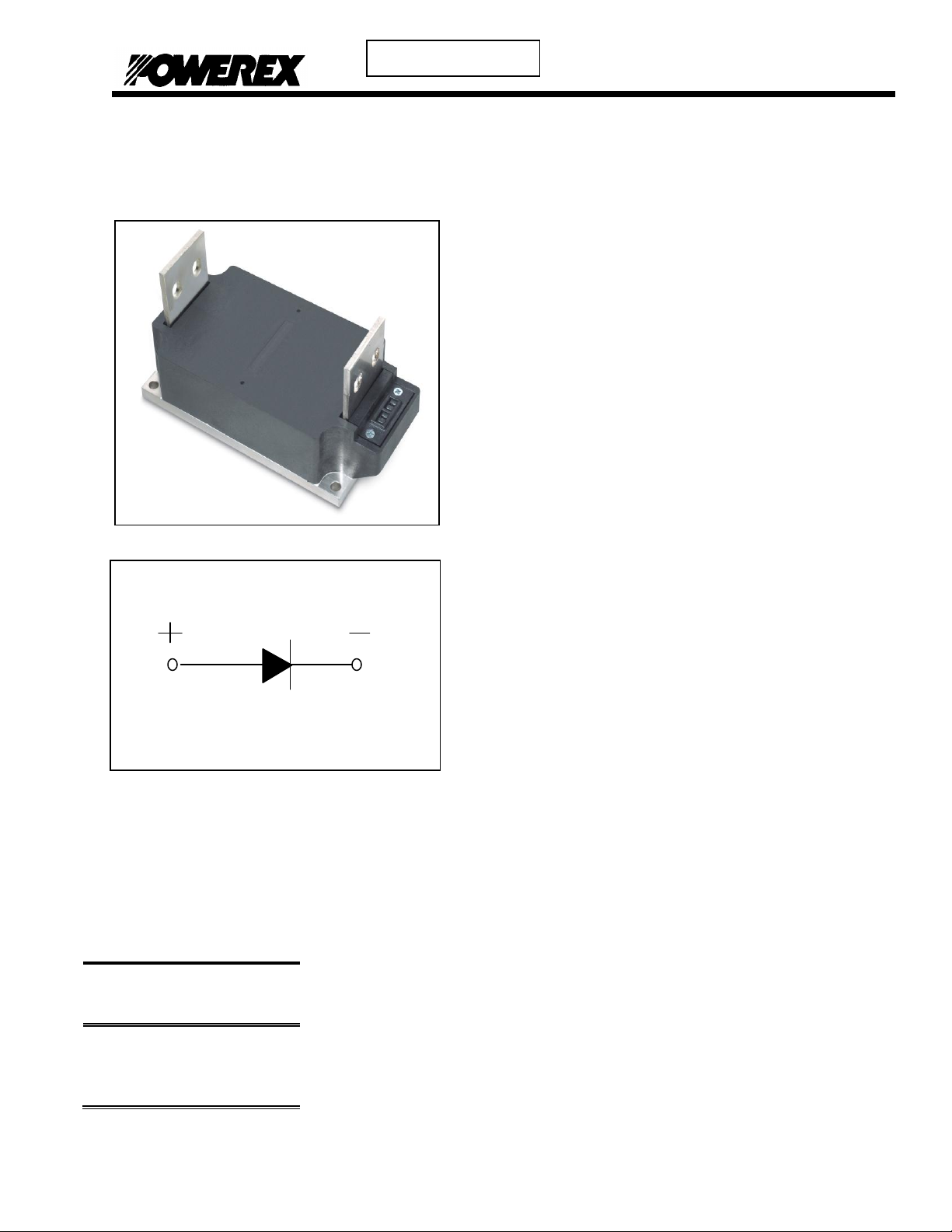
PS415008
®
Preliminary
Ordering Information:
Select the complete eight-digit
module part number from the table
below.
Example: PS415008 is a 5000 Volt,
800A Average Single Diode
Isolated POW-R-BLOKTM Module
Type
Voltage
Volts (x100)
Current
Amperes
(x100)
PS41
45
50
08
Description:
Powerex Single Diode Modules are designed
for use in applications requiring rectification
and isolated packaging. The modules are
isolated for easy mounting with other
components on a common heatsink.
Features:
Electrically Isolated Heatsinking
Compression Bonded Elements
Metal Baseplate
Low Thermal Impedance
for Improved Current Capability
Benefits:
No Additional Insulation
Components Required
Easy Installation
No Clamping Components
Required
Reduce Engineering Time
Applications:
Bridge Circuits
AC & DC Motor Drives
Battery Supplies
Power Supplies
Large IGBT Circuit Front Ends
Powerex, Inc., 173 Pavilion Lane, Youngwood, Pennsylvania 15697 (724) 925-7272 POW-R-BLOK
www.pwrx.com Single Diode Isolated Module
800 Amperes / Up to 5000 Volts
TM
Revision Date: 07/19/2012
Page 3

PS415008
®
Preliminary
Absolute Maximum Ratings
Characteristics
Conditions
Symbol
Units
Repetitive Peak Reverse Blocking Voltage
V
RRM
Up to 5000
V
Non-Repetitive Peak Blocking Voltage
(t < 5 msec)
V
RSM
V
RRM
+ 100V
V
RMS Current Per Diode
(180 o Conduction)
180 Conduction, TC=64C
180 Conduction, TC=89C
180 Conduction, TC=108C
I
F(RMS)
I
F(RMS)
I
F(RMS)
1570
1256
942
A
A
A
Average Forward Current Per Diode
(180 o Conduction)
180 Conduction, TC=64C
180 Conduction, TC=89C
180 Conduction, TC=108C
I
F(AV)
I
F(AV)
I
F(AV)
1000
800
600
A
A
A
Peak One Cycle Surge Current, Non-Repetitive
Tj = 25C, Vr = 0
60 Hz
50 Hz
I
FSM
I
FSM
41,760
37,930
A
A
Peak One Cycle Surge Current, Non-Repetitive
Tj = 25C, Vr = Vrrm
60 Hz
50 Hz
I
FSM
I
FSM
27,840
25,290
A
A
Peak One Cycle Surge Current, Non-Repetitive
Tj = 125C, Vr = 0
60 Hz
50 Hz
I
FSM
I
FSM
36,000
32,700
A
A
Peak One Cycle Surge Current, Non-Repetitive
Tj = 125C, Vr = Vrrm
60 Hz
50 Hz
I
FSM
I
FSM
24,000
21,800
A
A
Peak Three Cycle Surge Current, Non-Repetitive
60 Hz, Tj = 125C, Vr = Vrrm
I
FSM
19,270
A
Peak Ten Cycle Surge Current, Non-Repetitive
60 Hz, Tj = 125C, Vr = Vrrm
I
FSM
15,140
A
I2t for Fusing for One Cycle
Tj = 125C, Vr = Vrrm
8.3 milliseconds
10 milliseconds
I2t
I2t
2.39 x 10 6
2.38 x 10 6
A2 sec
A2 sec
I2t for Fusing for One Cycle
Tj = 25C, Vr = 0 V
8.3 milliseconds
10 milliseconds
I2t
I2t
7.24 x 10 6
7.19 x 10 6
A2 sec
A2 sec
Operating Temperature
TJ
-40 to +150
C
Storage Temperature
T
stg
-40 to +150
C
Max. Mounting Torque, M6 Mounting Screw
132
15
in. – Lb.
Nm
Max. Mounting Torque, M10 Terminal Screw
106
12
in. – Lb.
Nm
Module Weight, Typical
5.33
kg
11.75
lb
V Isolation @ 25C
60Hz V
rms
60 sec
V
rms
4500
V
Powerex, Inc., 173 Pavilion Lane, Youngwood, Pennsylvania 15697 (724) 925-7272 POW-R-BLOK
www.pwrx.com Single Diode Isolated Module
800 Amperes / Up to 5000 Volts
TM
Information presented is based upon manufacturers testing and projected capabilities.
This information is subject to change without notice.
The manufacturer makes no claim as to suitability of use, reliability, capability,
or future availability of this product.
Revision Date: 07/19/2012
Page 4

PS415008
®
Preliminary
Electrical Characteristics, TJ=25C unless otherwise specified
Characteristics
Symbol
Test Conditions
Min.
Max.
Units
Repetitive Peak Reverse Leakage Current
I
RRM
Up to 5000V, TJ=150C
600
mA
Peak On-State Voltage
VFM
IFM=3000A, TJ=150C
2.40
V
Threshold Voltage, Low-level
Slope Resistance, Low-level
V
(TO)1
rT1
TJ = 150C, I = 15%I
T(AV)
to πI
T(AV)
0.950
0.430
V
mΩ
Threshold Voltage, High-level
Slope Resistance, High-level
V
(TO)2
rT2
TJ = 150C, I = πI
T(AV)
to I
TSM
1.098
0.380
V
mΩ
VFM Coefficients, Full Range
TJ = 150C, I = 50A to 10kA
VFM = A+ B Ln I +C I + D Sqrt I
A =
B =
C =
D =
0.87766
0.01004
3.67 E-04
2.40 E-03
Typical Reverse Recovery Time
trr
TJ = 25C, Ifm = 1500A.
dIr/dt = 25 A/us, tp = 190 us
30
us
Thermal Characteristics
Characteristics
Symbol
Max.
Units
Thermal Resistance, Junction to Case
R
ΘJ-C
Per Module
0.043
C/W
Thermal Impedance Coefficients
Z
ΘJ-C
Z
ΘJ-C
= K1 (1-exp(-t/1))
+ K2 (1-exp(-t/2))
+ K3 (1-exp(-t/3))
+ K4 (1-exp(-t/4))
K1 = 1.85 E-04
K2 = 1.40 E-03
K3 = 2.90 E-03
K4 =3.90 E-02
1
= 1.53 E-03
2
= 4.52 E-02
3
= 1.32
4
= 19.17
Thermal Resistance, Case to Sink Lubricated
R
ΘC-S
Per Module
0.009
C/W
Powerex, Inc., 173 Pavilion Lane, Youngwood, Pennsylvania 15697 (724) 925-7272 POW-R-BLOK
www.pwrx.com Single Diode Isolated Module
800 Amperes / Up to 5000 Volts
TM
Revision Date: 07/19/2012
Page 5

PS415008
®
Preliminary
30°
90°
180°
0
200
400
600
800
1000
1200
1400
1600
1800
2000
0 100 200 300 400 500 600 700 800 900 1000
Max. Power Dissipation Per Diode -Watts
Average On-State Current - If(av) - Amperes
Maximum On-State Power Dissipation
(Sinusoidal Waveform)
30°
90°
180°
30
50
70
90
110
130
150
0 100 200 300 400 500 600 700 800 900 1000
Max. Case Temperature -Tcase -°C_
Average On-State Current - If(av) - Amperes
Maximum Allowable Case Temperature
(Sinusoidal Waveform)
60°
120°
180°
360°
0
500
1000
1500
2000
2500
3000
0 200 400 600 800 1000 1200 1400 1600
Max. Power Dissipation Per Diode -Watts
Average On-State Current -If(av) - Amperes
Maximum On-State Power Dissipation
(Rectangular Waveform)
60°
120°
180°
360°C
30
50
70
90
110
130
150
0 200 400 600 800 1000 1200 1400 1600
Max. Case Temperature -Tcase -°C
Average On-State Current -If(av) - Amperes
Maximum Allowable Case Temperature
(Rectangular Waveform)
0.00001
0.00010
0.00100
0.01000
0.10000
0.0001 0.001 0.01 0.1 1 10 100 1000
Thermal Impedance -Zjc - °C/W
Time - t - Seconds
Maximum Transient Thermal Impedance
(Junction to Case)
0.0
1.0
2.0
3.0
4.0
5.0
10 100 1000 10000
On-State Voltage - Vf - Volts
Instantaneous On-State Current - If Amperes
Maximum On-State Forward Voltage Drop
( Tj = 150 C )
Powerex, Inc., 173 Pavilion Lane, Youngwood, Pennsylvania 15697 (724) 925-7272 POW-R-BLOK
www.pwrx.com Single Diode Isolated Module
800 Amperes / Up to 5000 Volts
TM
Revision Date: 07/19/2012
Page 6

PS415008
®
Preliminary
1.0 10.0 100.0 1000.0
1,000
10,000
100,000
0.1 1 10 100
Duration of Surge (ms)
Peak Surge Current (A)
Number of Cycles @ 60Hz
Maximum Surge Current Ratings - 60Hz
Vr = Vrrm
Vr = 0V
Tj initial = 125oC
1 10 100 1000
1,000
10,000
100,000
0.1 1 10 100
Duration of Surge (ms)
Peak Surge Current (A)
Number of Cycles @ 50Hz
Maximum Surge Ratings - 50Hz
Vr = Vrrm
Vr = 0V
Tj initial = 125oC
1.0 10.0 100.0 1000.0
1.00E+05
1.00E+06
1.00E+07
1.00E+08
0.1 1 10 100
Duration of Surge (ms)
Maximum I
2
t (A)
Number of Cycles @ 60Hz
Maximum I2t Ratings - 60Hz
Vr = Vrrm
Vr = 0V
Tj initial = 125oC
1.0 10.0 100.0 1000.0
1.00E+05
1.00E+06
1.00E+07
1.00E+08
0.1 1 10 100
Duration of Surge (ms)
Maximum I
2
t (A)
Number of Cycles @ 50Hz
Maximum I2t Ratings - 50Hz
Vr = Vrrm
Vr = 0V
Tj initial = 125oC
Powerex, Inc., 173 Pavilion Lane, Youngwood, Pennsylvania 15697 (724) 925-7272 POW-R-BLOK
www.pwrx.com Single Diode Isolated Module
800 Amperes / Up to 5000 Volts
TM
Revision Date: 07/19/2012
Page 7

PS415008
®
Preliminary
Powerex, Inc., 173 Pavilion Lane, Youngwood, Pennsylvania 15697 (724) 925-7272 POW-R-BLOK
www.pwrx.com Single Diode Isolated Module
800 Amperes / Up to 5000 Volts
TM
Revision Date: 07/19/2012
 Loading...