

Page 1
PowIRtab Mounting Guidelines
by Paul W estmarland & Pamela Dugdale
AN-1010
1.0 Introduction
The PowIRtabTM package has been designed to fill the
gap in the market between the TO-247, more expensive
metal case devices & non-isolated power modules. It is
the natural replacement for metal case outlines such as
DO-4 & DO-5, but it is also suitable for new innovative
solutions, thanks to a package outline that combines low
profile, excellent die to footprint ratio & sturdy
connectivity . It utilises a large lead for high current
connection, carrying both a mounting hole & PCB
insertion pins. The body is compatible with a T0-218
outline, with an exposed heatsink & non-isolated mounting
hole.
It is anticipated that the devices would find typical
applications in busbar assemblies or finned heatsinks,
reducing component count & cost of ownership.
2.0 Scope
This application note covers the various fixment methods
that are possible with this device, & the associated thermal
properties resulting from their use:
a) Optimum mounting torque.
b) T ype of fixings.
c) Effect of torque on thermal resistance (‘wet’ & ‘dry’).
d) Effect of pressure on contact thermal resistance (‘wet’
& ‘dry’).
3.0 Mechanical Considerations
3.1 T ype of Fixings
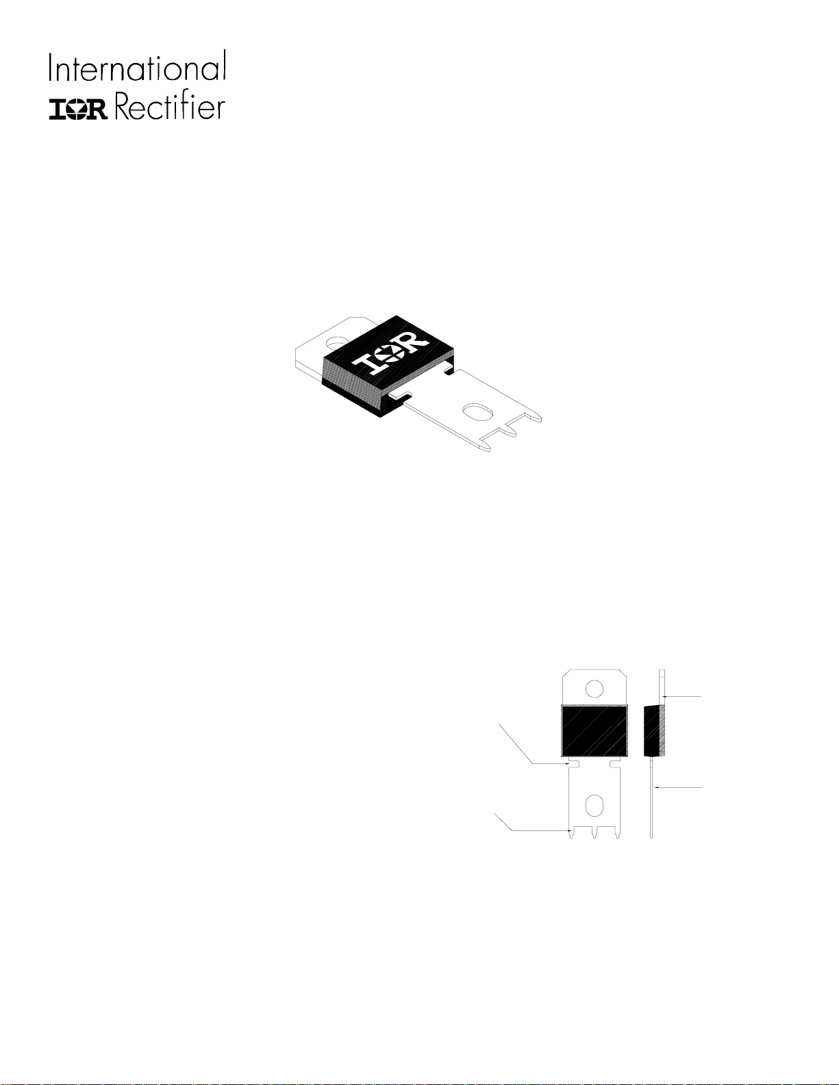
The PowIRtabTM possesses mounting holes in the tab &
lead for electrically connecting the device to heatsinks or
busbars. The lead also carries PCB insertion pins so that
the lead end may be soldered into a board.
Tab (Header)
Stress relief slots
Lead
PCB insertion
pins
Figure 1
3.2 T ab Connection
Using the mounting hole in the tab allows a designer to
attach the PowIRtabTM to a heatsink. The tab of a
PowIRtabTM acts as one of the terminals. There is no
common additional lead, so the mounting hole contact
must be very good, with the heatsink forming part of the
circuit. For the best results the surface of the heatsink must
Page 2
Application Note
be as smooth & flat as possible to maximise the contact
area of the tab. A good flatness specification would be
0.02mm (0.0007ins) maximum per 10mm (0.393ins).
Ensure also that the heatsink mounting hole has been
deburred.
The mounting hole in the tab is designed to accept a M4
screw , No.6-32 screw or 6-40 screw . A self tapping type
screw may also be used. However, only a certain type of
screw & washer may be used to attach the tab to the
heatsink because of the proximity of the mounting hole to
the plastic body .
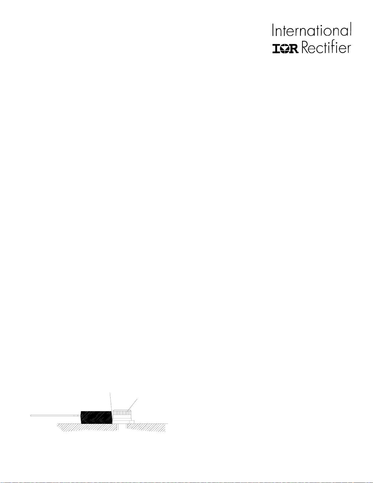
The recommended method of attachment is a socket
headed M4 screw , with a plain washer, as shown in the
figure 2. The washer used must be no larger than the
diameter of the socket head. If a larger washer is used, it
can bear directly on the edge of the plastic body , causing
the body to crack when the screw is tightened. . The
largest possible diameter washer that may be used is
7.2mm (0.283ins). An alternative is a suitably sized
rectangular washer.
Similarly , M4 nuts cannot be used (on the plastic side)
for the tab connection, since there is inadequate clearance
between the hole & plastic body to rotate the nut. Using
the plastic body to prevent the nut rotating will inevitably
crack the plastic & is not recommended.
Rivets may be used but the following precautions must be
noted:
The diameter of the hole in the heatsink must be of a
smaller diameter than that of the PowIRtabTM mounting
hole, the crimping force is controlled to give a slow
pressure build-up & the rivet used must be of a soft
material. T oo high a crimping speed & pressure is likely to
Small clearance
between washer &
plastic body.
M4 socket headed
bolt
damage the die inside the package & deform the header,
lifting it away from the heatsink.
Wherever possible, the use of heatsink compound is
recommended to mount the package to improve the heat
dissipation.
The recommended mounting torques, with & without
heatsink compound, may found under section 4.1 of this
application note - ‘Contact thermal resistance as a function
of torque on the mounting screw’ & also in summary form
in Section 5.0.
3.3 Clip mounting
If desired, use may be made of a clip to attach the
package to a heatsink. The recommended point for the
placement of the clip is directly over the die, ie in the
middle of the plastic body . This will give the best contact
thermal resistance. Please refer to Application Note AN997 ‘Mounting Guidelines for the Super-247’ for the
different types of clip available, since the type of clips
demonstrated in this note apply equally well to the
PowIRtabTM package. Also refer to section 4.2 & 5.0 of
this application note for the optimum clip force.
3.4 Lead connection
The mounting hole in the lead of the PowIRtabTM is oval
in shape. This slotted hole allows for some movement
between the two mounting holes in an assembly , & for any
assembly tolerances. Any M4 screw , No.6-32 or 6-40
screw or nut combination may be used to secure the lead.
The use of a plane & spring washer is recommended to
allow for movement of the lead due to thermal expansion
or vibration. This will also, along with the stress relief slots,
minimise the possibility of the plastic body cracking under
tension/compression stresses. The step difference between
the back of the heatsink & the back of the lead is
nominally 3.0mm. This means that in busbar
configurations, the lead will either need forming down to
the same level as the heatsink, or the lead busbar will need
to be raised by 3.0mm to the same level as the back of the
lead. A typical busbar configuration is shown in Figure 3.
Figure 2
Care must be taken when tightening the fixing to prevent
distortion of the lead. The lead fixing can be typically
tightened to 3.00Nm (2.21 lbf/ft) without distortion.
Page 3
Application Note
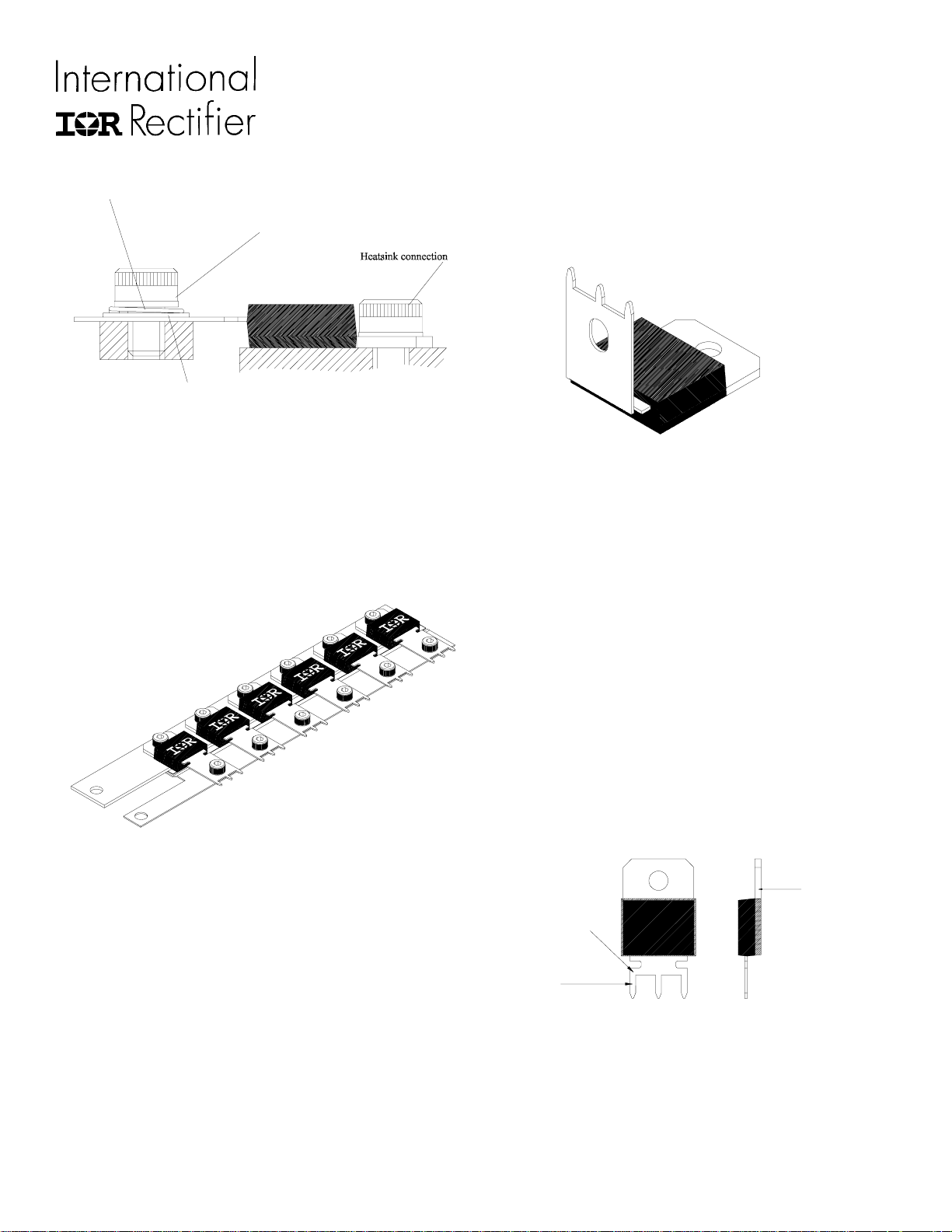
Sprung washer
Busbar connection to lead
Plain washer
Figure 3
Another solution is a laminated busbar, as supplied by the
Rogers Mektron Busbar Division. Here a single busbar is
stamped to the step height of the package & an isolating
laminate & second busbar added. The PowIRtab
TM
packages can then be bolted (or rivetted) down to this
strip to form a single assembly , with two large single
outputs. A typical example is shown below in Figure 4.
16.6mm (0.653ins). The stress relief slots, as well as
making the leadforming operation simpler, help to reduce
the stresses imposed on the plastic body caused by
PowIRtab with 90
degree leadform
Figure 5
differential expansion at higher operating temperatures.
During the leadforming operation, it is very important that
the area of lead between the plastic & the bend is securely
clamped, to ensure that the plastic is not cracked by this
operation.
Care must also be taken not flex or bend the lead over
sharp angles repeatedly . If the lead is bent through 30
degrees & back again more than twice, it will be
considerably weakened & liable to breakage.
Figure 4
3.5 Leadforming
In some applications, forming or bending the lead to an
angle of 90 degrees is desirable (Figure 5). This could
facilitate connection to a PCB situated above the package.
The minimum recommended distance of the bend point
from the plastic body is 2.50mm (0.098ins). This will
produce a leadform as shown in Figure 5.
This particular leadform is offered as an option direct
from IR, under the designated leadform option LF-68.The
form occurs at the lower edge of the stress relief slots in
the lead. The vertical height of the lead, measured from the
underside of the unformed section of lead is typically
Another type of leadform under development is a
PowIRtab
TM
with the lead shortened to form 3 short leads,
as shown below in Figure 6. The use of this outline would
allow a lower profile insertion of the package into PCBs
than that of the standard outline.
Tab (Header)
Shortened lead
PCB insertion
pins
Figure 6
This lead option would work well in applications where
greater power than a T0-247 is required, but the designer
wishes to retain the basic mechanical structure & PCB. A
good example would be that of an OR-ing application with
a higher output current.
Page 4
Application Note
4.0 Thermal Considerations
One of the major considerations when mounting all
power semiconductor packages is the dissipation of heat.
This is because the performance of the device is limited by
the junction temperature of the die and the glass transition
temperature of the plastic. Indeed there are maximum
allowable temperatures above which the device is not
functional. The way in which a device is mounted can have
a large effect on the thermal contact between the header
and the heatsink and hence on the ability of the package to
dissipate heat. This is often referred to as the contact
thermal resistance and is quoted in datasheets. A full
discussion of all of the components that make up the
thermal resistance of a power semiconductor package is
given in AN-997. In the present note we shall concentrate
on the thermal resistance between the case and the
heatsink as this is the most dependent on the mounting
technique.
The physical source of the contact resistance is a result
of the fact that surfaces are never perfectly flat. Even for
two well prepared surfaces contact only actually occurs at
several points separated by large air gaps. As air is a very
good thermal insulator this is undesirable and increases the
thermal resistance. There are two ways of reducing the
volume of air trapped between the surfaces. One is to
increase the force holding the two surfaces together and
the other is to improve the quality of the contact area by
filling in the gaps. In the case of the former this can be
done by either applying a force above the die with a clip or
by increasing the torque on the screw which mounts the
tab to the heatsink. The second technique requires the use
of a heatsinking compound. This is usually a silicone grease
loaded with electrically insulating, thermally conductive
material such as alumina. The purpose of the grease is to
fill the gaps without increasing the distance between the
two surfaces. If the layer of grease is too thick then the
thermal resistance will be increased. When using
heatsinking compound in conjunction with a PowirtabTM it is
important to remember that electrical contact to the drain
can only be made through the mounting tab. In addition to
this, care must be taken to avoid getting any compound in
the screw threads or mounting holes as this will affect the
accuracy of the torque measurement.
For the purpose of this application note the contact
thermal resistance has been measured as a function of both
the torque on the mounting screw and the force above the
die. In both cases measurements have been performed
with and without heatsinking compound.
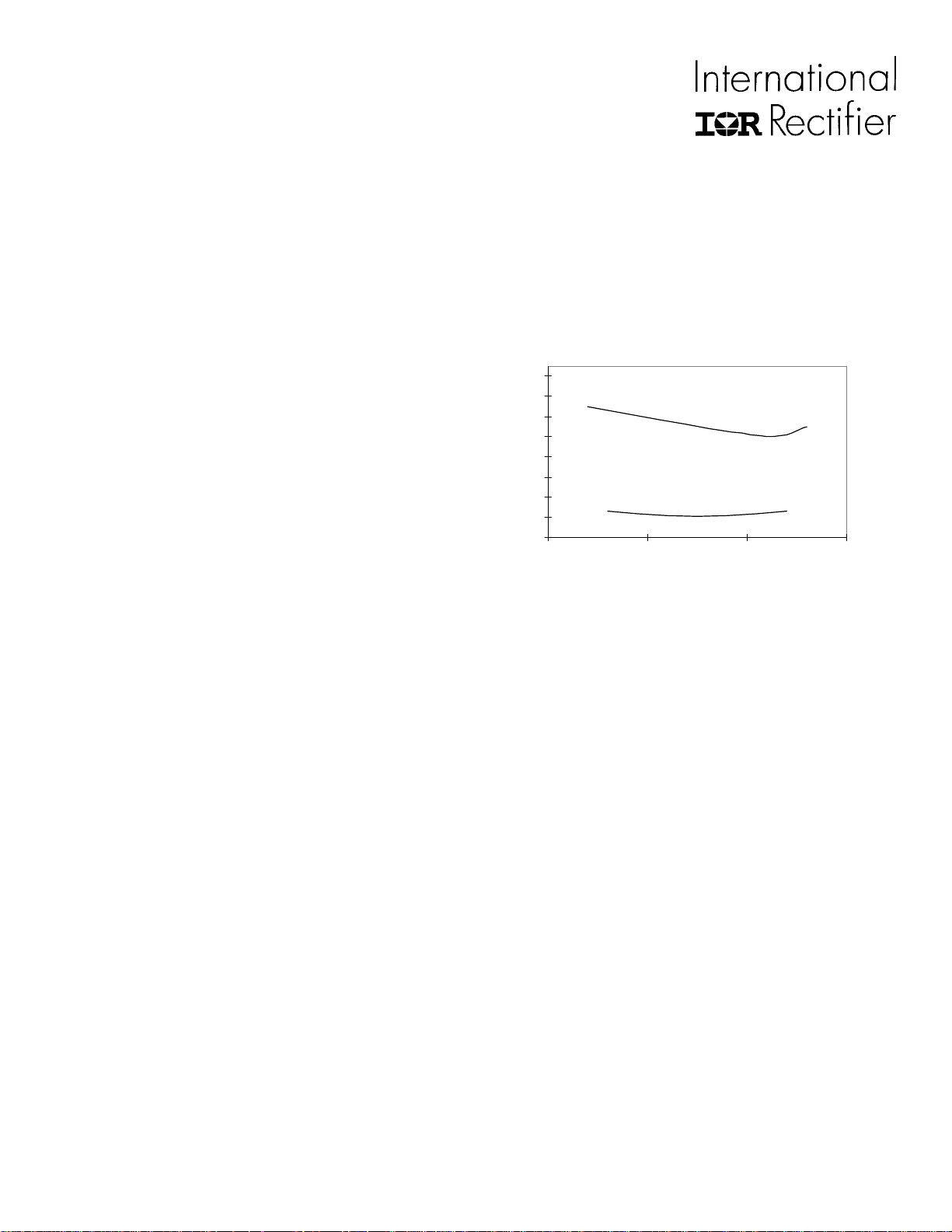
4.1 Contact Thermal resistance as a Function of T orque
on the Mounting Screw .
1.6
1.4
1.2
1
0.8
0.6
0.4
Thermal Resistance C/W
0.2
0
Dry Mounting
With Heatsink Compound
00.511.5
Torque / Nm
Figure 7
Figure 7 shows the contact thermal resistance as a
function of torque with and without heatsink compound.
The package was mounted using a M4 screw in
accordance with the mounting instructions described in this
application note. It can be seen from the graph that in the
case of a dry mounted device the contact thermal
resistance can be reduced to a minimum of 1oC/W by
increasing the torque up to an optimum value of 1.1 Nm.
Further increasing the torque is not beneficial since the
header/mounting tab becomes deformed, lifting the
package away from the heatsink and hence increasing the
thermal resistance. The use of heatsink compound reduces
the thermal resistance by a factor of 78% to 0.220C/W .
The dependence on torque is also reduced. This
measurement was acheived using a device with 60W
power applied for 100secs, on an ‘infinite’ heatsink.
Recommended torque:
Without heatsink compound: 1.1 Nm (0.81lbf ft) to give a
thermal resistance, case to sink, of 1 0C/W .
With heatsink compound: 0.8 Nm (0.59lbf ft) to give a
thermal resistance, case to sink, of 0.22 0C/W .
Page 5
Application Note
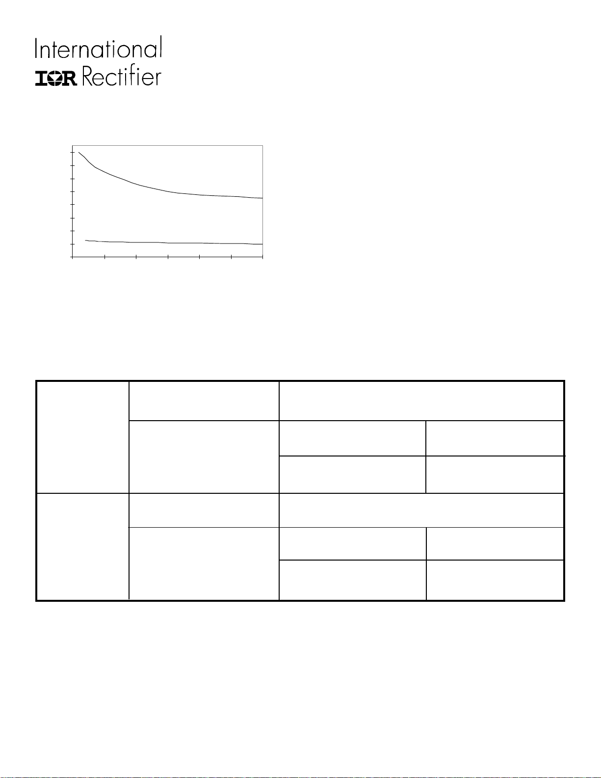
4.2 Contact Thermal resistance as a Function of Force
Above the Die (Clip Mounting).
1.6
1.4
1.2
1
0.8
0.6
0.4
Thermal Resistance C/W
0.2
0
0 50 100 150 200 250 300
Figure 8
With Heatsink Compound
Force / N
Dr y Mounting
Figure 8 shows the contact thermal resistance as a
function of force above the die with and without heatsink.
It can be seen from the graph that when heatsink
5.0 Summary Table
Screw Mounting Maximum allowable torque
(Tab & lead)
compound is not used the contact resistance decreases
with increasing force. However there is a point beyond
which the advantage gained by increasing the force is
offset by the additional cost required to do so. The use of
heatsink compound reduces the thermal resistance by a
factor of 85% and also makes the thermal resistance less
dependent on the applied force.
This measurement was acheived using a device with
60W power applied for 100secs, on an ‘infinite’ heatsink.
Recommended force:
Without heatsink compound: 20N (4.5lbf) minimum to
give a thermal resistance, case to sink, of 1.5oC/W .
With heatsink compound: 20N (4.5lbf) minimum to give a
thermal resistance, case to sink, of 0.23oC/W .
3Nm (2.2 lbf ft)
Thermal mounting
Clip Mounting Maximum allowable force
Thermal mounting Without heatsink compound
Without heatsink compound
With heatsink compound
250N (56.21lbf)
With heatsink compound
Laminated Busbar supplier
Rogers Mektron Busbar Division
Rogers N.V.
Afrikalaan 188,9000 Gent
Belgium
1oC/W @ 1.1Nm
0.22oC/W @ 0.8Nm
1.5oC/W @ 20N
0.23oC/W @ 20N
 Loading...