

Page 1

6121 Baker Road,
Suite 108
Minnetonka, MN 55345
www.chtechnology.com
Phone (952) 933-6190
Fax (952) 933-6223
1-800-274-4284
Thank you for downloading this document from C&H Technology, Inc.
Please contact the C&H Technology team for the following questions -
Technical
Application
Assembly
Availability
Pricing
Phone – 1-800-274-4284
E-Mail – sales@chtechnology.com
www.chtechnology.com - SPECIALISTS IN POWER ELECTRONIC COMPONENTS AND ASSEMBLIES - www.chtechnology.com
Page 2

PM75CLB120
V
CC
SIGND GND
OUT
F
O
IN
OT
V
CC
SIGND GND
OUT
F
O
IN
OT
V
CC
SIGND GND
OUT
F
O
IN
OT
V
CC
SIGND GND
OUT
F
O
IN
OT
PU
U
N
NC
F
O
V
NC
W
N
VN1V
N
V
WPC
W
P
W
FO
V
WP1
V
VPC
V
P
V
FO
V
VP1
V
UPC
U
P
U
FO
V
UP1
VWNNC
V
CC
SIGND GND
OUT
F
O
IN
OT
V
CC
SIGND GND
OUT
F
O
IN
OT
19 FO
17 VN
14 VN1
11 WP
8 VVP1
2 UFO
6 VFO
5 VVPC
3 UP
7 VP
9 VWPC
10 WFO
12 VWP1
1 VUPC
4 VUP1
16 UN
15 NC
18
WN
13 VNC
TERMINAL
CODE
E D
A
GF
L
M
H J J J
KK
K K
V
AB
(4 PLACES)
V
N
W
X B
V
V
V
V
V
V
V
V
S T UU U
R
P Q
AC
(2 PLA
CES)
AJ
AH
AF
AG
AL
AN
AK
C
AD
AE
(2 PLACES)
AM
V
V
Y
Y
Z
AA
N
P
1 5 9 13 1
9
WVUB
Powerex, Inc., 200 E. Hillis Street, Youngwood, Pennsylvania 15697-1800 (724) 925-7272
Intellimod™ L-Series
Three Phase
IGBT Inverter
75 Amperes/1200 Volts
Description:
Powerex Intellimod™ Intelligent
Power Modules are isolated base
modules designed for power
switching applications operating
at frequencies to 20kHz. Built-in
control circuits provide optimum
gate drive and protection for the
IGBT and free-wheel diode
power devices.
Outline Drawing and Circuit Diagram
Dimensions Inches Millimeters
A 4.72 120.0
B 2.17 55.0
C 0.63 16.0
D 4.17 106.0
E 0.28 7.0
F 0.78 19.75
G 2.62 66.5
H 0.13 3.25
J 0.63 16.0
K 0.08 2.0
L 0.10 2.5
M 2.81 71.5
N 0.20 5.0
P 0.31 7.75
Q 3.87 98.25
R 0.87 22.0
S 0.10 2.5
T 0.77 19.5
U 0.91 23.0
Dimensions Inches Millimeters
V 0.16 4.0
W 1.01 25.75
X 2.00 50.75
Y 0.69 17.5
Z 0.30 7.5
AA 0.98 25.0
AB 0.10 Dia. Dia. 2.5
AC 0.22 Dia. Dia. 5.5
AD 0.67 17.0
AE 0.10 Dia. Dia. 2.5
AF 0.33 8.5
AG 0.08 2.0
AH 0.41 10.5
AJ 1.08 27.5
AK 0.04 1.0
AL 0.02 Sq. Sq. 0.5
AM 0.06 1.5
AN 0.04 1.0
Features:
£ Complete Output Power
Circuit
£ Gate Drive Circuit
£ Protection Logic
– Short Circuit
– Over Temperature
Using On-chip
Temperature Sensing
– Under Voltage
£ Low Loss Using 5th
Generation IGBT Chip
Applications:
£ Inverters
£ UPS
£ Motion/Servo Control
£ Power Supplies
Ordering Information:
Example: Select the complete
part number from the table below
-i.e. PM75CLB120 is a 1200V,
75 Ampere Intellimod™ Intelligent
Power Module.
Type Current Rating V
Amperes Volts (x 10)
CES
PM 75 120
1
Page 3

Powerex, Inc., 200 E. Hillis Street, Youngwood, Pennsylvania 15697-1800 (724) 925-7272
PM75CLB120
Intellimod™ L-Series
Three Phase IGBT Inverter
75 Amperes/1200 Volts
Absolute Maximum Ratings, Tj = 25°C unless otherwise specified
Characteristics Symbol PM75CLB120 Units
Power Device Junction Temperature Tj -20 to 150 °C
Storage Temperature T
-40 to 125 °C
stg
Mounting Torque, M5 Mounting Screws — 31 in-lb
Module Weight (Typical) — 340 Grams
Supply Voltage, Surge (Applied between P - N) V
Self-protection Supply Voltage Limit (Short Circuit protection Capability)* V
CC(surge)
CC(prot.)
Isolation Voltage, AC 1 minute, 60Hz Sinusoidal V
*VD = 13.5 ~ 16.5V, Inverter Part, Tj = 125°C
1000 Volts
800 Volts
2500 Volts
ISO
IGBT Inverter Sector
Collector-Emitter Voltage (VD = 15V, V
Collector Current (TC = 25°C) ±IC 75 Amperes
Peak Collector Current (TC = 25°C) ±ICP 150 Amperes
Collector Dissipation (TC = 25°C) PC 457 Watts
= 15V) V
CIN
1200 Volts
CES
Control Sector
Supply Voltage (Applied between V
Input Voltage (Applied between UP-V
UP1-VUPC
UPC
Fault Output Supply Voltage VFO 20 Volts
(Applied between UFO-V
UPC
, VFO-V
VPC
Fault Output Current (UFO, VFO, WFO, FO Terminals) IFO 20 mA
, V
, VP-V
, WFO-V
VP1-VVPC
, WP-V
VPC
, FO-VNC)
WPC
, V
WP1-VWPC
, UN- VN- WN-VNC) V
WPC
, VN1-VNC) VD 20 Volts
20 Volts
CIN
Electrical and Mechanical Characteristics, Tj = 25°C unless otherwise specified
Characteristics Symbol Test Conditions Min. Typ. Max. Units
IGBT Inverter Sector
Collector-Emitter Cutoff Current I
VCE = V
Diode Forward Voltage VEC -IC = 75A, V
Collector-Emitter Saturation Voltage V
Tj = 25°C
VD = 15V, V
Tj = 125°C
Inductive Load Switching Times ton 0.5 1.0 2.5 µs
trr VD = 15V, V
t
t
t
VCE = V
CES
VD = 15V, V
CE(sat)
VCC = 600V, IC = 75A — 0.4 1.0 µs
C(on)
Tj = 125°C — 2.0 3.0 µs
off
— 0.7 1.2 µs
C(off)
, VD = 15V, Tj = 25°C — — 1.0 mA
CES
, VD = 15V, Tj = 125°C — — 10 mA
CES
= 15V, VD = 15V — 2.5 3.5 Volts
CIN
= 0V, IC = 75A, — 1.8 2.3 Volts
CIN
= 0V, IC = 75A, — 1.9 2.4 Volts
CIN
= 0 ⇔ 15V — 0.5 0.8 µs
CIN
2
Page 4

Powerex, Inc., 200 E. Hillis Street, Youngwood, Pennsylvania 15697-1800 (724) 925-7272
Y
X
BOTTOM VIEW
PM75CLB120
Intellimod™ L-Series
Three Phase IGBT Inverter
75 Amperes/1200 Volts
Electrical and Mechanical Characteristics, Tj = 25°C unless otherwise specified
Characteristics Symbol Test Conditions Min. Typ. Max. Units
Control Sector
Short Circuit Trip Level SC -20°C ≤ Tj ≤ 125°C, VD = 15V 150 — — Amperes
Short Circuit Current Delay Time t
Over Temperature Protection OT Trip Level 135 145 155 °C
(Detect Tj of IGBT Chip) OTR Reset Level — 125 — °C
Supply Circuit Under-voltage Protection UV Trip Level 11.5 12.0 12.5 Volts
(-20 ≤ Tj ≤ 125°C) UVR Reset Level — 12.5 — Volts
Circuit Current ID VD = 15V, V
VD = 15V, V
Input ON Threshold Voltage V
Input OFF Threshold Voltage V
Fault Output Current* I
I
Fault Output Pulse Width* tFO VD = 15V 1.0 1.8 — ms
*Fault output is given only when the internal SC, OT and UV protections schemes of either upper or lower devide operate to protect it.
VD = 15V — 0.2 — µs
off(SC)
= 15V, VN1-VNC — 15 25 mA
CIN
Applied between UP-V
th(on)
VP-V
th(off)
VD = 15V, V
FO(H)
VD = 15V, V
FO(L)
VPC
, WP-V
= 15V, V
CIN
WPC
XP1-VXPC
UPC
, UN- VN- WN-VNC 1.7 2.0 2.3 Volts
= 15V — — 0.01 mA
CIN
= 15V — 10 15 mA
CIN
— 5 10 mA
, 1.2 1.5 1.8 Volts
Thermal Characteristics
Characteristic Symbol Condition Min. Typ. Max. Units
Junction to Case Thermal Resistance R
R
Contact Thermal Resistance R
IGBT (Per 1/6 Module) — — 0.21 °C/Watt
th(j-c)Q
FWDi (Per 1/6 Module) — — 0.30 °C/Watt
th(j-c)D
Case to Fin Per Module, — — 0.038 °C/Watt
th(c-f)
Thermal Grease Applied
Recommended Conditions for Use
Characteristic Symbol Condition Value Units
Supply Voltage VCC Applied across P-N Terminals ≤800 Volts
Control Supply Voltage** VD Applied between V
V
Input ON Voltage V
Input OFF Voltage V
PWM Input Frequency f
Arm Shoot-through Blocking Time t
** With ripple satisfying the following conditions: dv/dt swing ≤ ±5V/µs, Variation ≤ 2V peak to peak.
Applied between UP-V
CIN(on)
VP-V
CIN(off)
— ≤20 kHz
PWM
Input Signal ≥2.5 µs
DEAD
VP1-VVPC
VPC
, V
WP1-VWPC, VN1-VNC
, WP-V
, UN- VN- WN-VNC ≥9.0 Volts
WPC
TC Measurement Point
Arm UP VP WP UN VN WN
Axis IGBT FWDi IGBT FWDi IGBT FWDi IGBT FWDi IGBT FWDi IGBT FWDi
X 28.3 28.3 65.0 65.0 87.0 87.0 39.3 39.3 54.0 54.0 76.0 76.0
Y -8.2 2.0 -8.2 2.0 -8.2 2.0 6.2 -4.0 6.2 -4.0 6.2 -4.0
UP1-VUPC
, 15.0 ± 1.5 Volts
, ≤0.8 Volts
UPC
3
Page 5
Powerex, Inc., 200 E. Hillis Street, Youngwood, Pennsylvania 15697-1800 (724) 925-7272
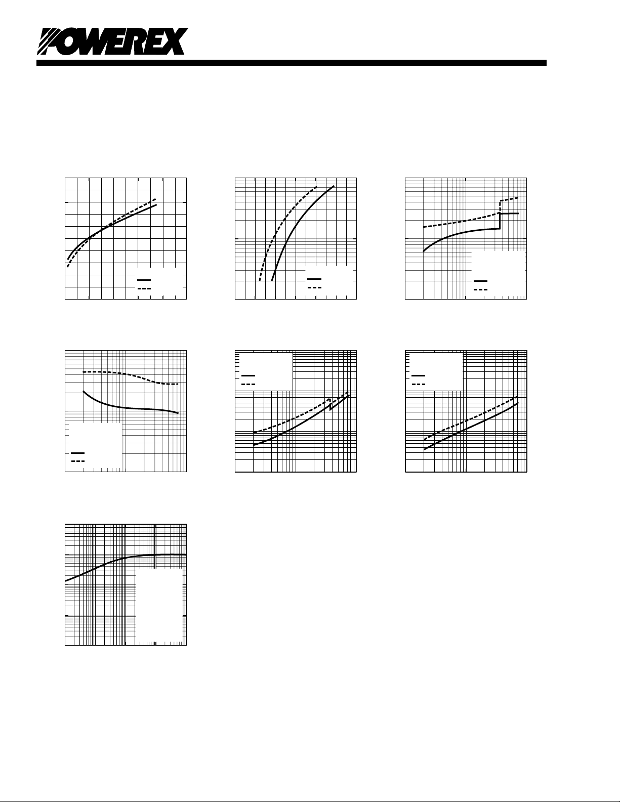
VCC = 600V
VD = 15V
INDUCTIVE LOAD
Tj = 25°C
Tj = 125°C
VCC = 600V
VD = 15V
Tj = 25°C
Tj = 125°C
VCC = 600V
VD = 15V
Tj = 25°C
Tj = 125°C
VCC = 600V
VD = 15V
INDUCTIVE LOAD
Tj = 25°C
Tj = 125°C
EMITTER CURRENT, IE, (AMPERES)
REVERSE RECOVERY CURRENT, I
rr
, (AMPERES)
10
2
10
0
10
1
10
1
10
0
10
2
10
0
10
0
10
1
10
-1
10
-2
10
2
EMITTER CURRENT, IE, (AMPERES)
REVERSE RECOVERY TIME, t
rr
, (µs)
COLLECTOR CURRENT, IC, (AMPERES)
SWITCHING LOSS, E
SW(on)
, (mJ/PULSE)
10
2
10
1
10
0
10
1
10
0
10
-1
10
2
10
2
10
1
10
0
10
1
10
0
10
-1
10
2
SWITCHING LOSS (ON) VS.
COLLECTOR CURRENT (TYPICAL)
COLLECTOR CURRENT, IC, (AMPERES)
SWITCHING LOSS, E
SW(off)
, (mJ/PULSE)
SWITCHING LOSS (OFF) VS.
COLLECTOR CURRENT (TYPICAL)
REVERSE RECOVERY CHARACTERISTICS
(TYPICAL)
EMITTER-COLLECTOR VOLTAGE, VEC, (VOLTS)
EMITTER CURRENT, I
E
, (AMPERES)
FREE-WHEEL DIODE
FORWARD CHARACTERISTICS
(TYPICAL)
0 2.0 3.02.51.51.00.5
10
2
10
1
10
0
VD = 15V
Tj = 25°C
Tj = 125°C
TIME, (s)
TRANSIENT THERMAL
IMPEDANCE CHARACTERISTICS
(IGBT & FWDi)
10
1
10
-1
10
-2
10
-3
10
0
10
1
10
0
10
-1
10
-3
10
-2
Z
th
= R
th
• (NORMALIZED VALUE)
Single Pulse
TC = 25°C
Per Unit Base =
R
th(j-c)
=
0.27°C/W
(IGBT)
R
th(j-c)
=
0.39°C/W
(FWDi)
NORMALIZED TRANSIENT THERMAL IMPEDANCE, Z
th(j-c')
REVERSE RECOVERY CHARACTERISTICS
(TYPICAL)
COLLECTOR-CURRENT, IC, (AMPERES)
COLLECTOR-EMITTER
SATURATION VOLTAGE,
V
CE(sat)
, (VOLTS)
COLLECTOR-EMITTER
SATURATION VOLTAGE CHARACTERISTICS
(TYPICAL - INVERTER PART)
0 40 1008060
VD = 15V
Tj = 25°C
Tj = 125°C
20
2.5
2.0
1.5
1.0
0.5
0
PM75CLB120
Intellimod™ L-Series
Three Phase IGBT Inverter
75 Amperes/1200 Volts
4
 Loading...