

Page 1

6121 Baker Road,
Suite 108
Minnetonka, MN 55345
www.chtechnology.com
Phone (952) 933-6190
Fax (952) 933-6223
1-800-274-4284
Thank you for downloading this document from C&H Technology, Inc.
Please contact the C&H Technology team for the following questions -
Technical
Application
Assembly
Availability
Pricing
Phone – 1-800-274-4284
E-Mail – sales@chtechnology.com
www.chtechnology.com - SPECIALISTS IN POWER ELECTRONIC COMPONENTS AND ASSEMBLIES - www.chtechnology.com
Page 2

PM50RVA120
OUT
TEMP
Si
GND
VN1
WN
VNC
F
O
Br
B N W V U P
V
CC
F
O
IN
TH
GND
OUT
Si
GND
VN
V
CC
F
O
IN
GND
OUT
Si
GND
UN
V
CC
F
O
IN
GND
OUT
Si
GND
V
WP1
W
P
W
FO
V
FO
U
FO
V
WPC
V
CC
F
O
IN
GND
OUT
Si
GND
V
VP1
V
P
V
VPC
V
CC
F
O
IN
GND
OUT
Si
GND
V
UP1
U
P
V
UPC
V
CC
F
O
IN
GND
Rf
O
= 1.5k OHM
S NUTS (6 TYP.)
T (4 TYP.)
DP
A
B K E
1 2 34
5 6 78
9 10 111
2
1314 1516
1718 19
N P B
U V
W
J
TYP.
N
V
U
R
P
U
M
L - TYP.
M
C
G
F
H
Y
X W
Z - TYP.
AA - TYP.
BB SQ PIN - TYP.
(19 PLACES)
CCØ
(4 PLACES)
TERMINAL CODE
1. W
FO
2. V
WPC
3. WP
4. V
WP1
5. VFO
6. VVPC
7. VP
8. VVP1
9. UFO
10. VUPC
11. U
P
12. V
UP1
13. Br
14. F
O
15. VNC
16. VN1
17. UN
18. VN
19. WN
DETAIL A
SEE
DETAIL A
OUT
Si
GND
V
CC
F
O
IN
GND
Rf
O
Powerex, Inc., 200 E. Hillis Street, Youngwood, Pennsylvania 15697-1800 (724) 925-7272
Outline Drawing and Circuit Diagram
Dimensions Inches Millimeters
A 4.33 110.0
B 3.50 89.0
C 0.87 +0.04/-0.02 22.0 +1.0/-0.5
D 3.74±0.010 95.0±0.25
E 2.91±0.010 74.0±0.25
F 0.16 4.0
G 0.87 22.0
H 0.42 10.6
J 0.79 20.0
K 2.99±0.02 76.0±0.5
L 0.39 10.0
M 0.49 12.5
N 0.67 17.0
Dimensions Inches Millimeters
P 0.30 7.5
R 0.65 16.5
S M5 Metric M5
T 0.22 Dia. Dia. 5.5
U 0.56±0.010 14.1±0.25
V 1.72±0.012 43.57±0.3
W 0.57±0.012 14.6±0.3
X 2.90 73.7
Y 0.78 19.7
Z 0.10±0.010 2.54±0.25
AA 1.37±0.010 3.49±0.25
BB 0.02 SQ 0.64 SQ
CC 0.12 +0.04/-0.02 3.0 +1.0/-0.5
Intellimod™ Module
Three Phase + Brake
IGBT Inverter Output
50 Amperes/1200 Volts
Description:
Powerex Intellimod™ Intelligent
Power Modules are isolated base
modules designed for power
switching applications operating
at frequencies to 20kHz. Built-in
control circuits provide optimum
gate drive and protection for the
IGBT and free-wheel diode
power devices.
Features:
£ Complete Output Power
Circuit
£ Gate Drive Circuit
£ Protection Logic
– Short Circuit
– Over Temperature
– Under Voltage
Applications:
£ Inverters
£ UPS
£ Motion/Servo Control
£ Power Supplies
Ordering Information:
Example: Select the complete
part number from the table below
-i.e. PM50RVA120 is a 1200V,
50 Ampere Intellimod™ Intelligent
Power Module.
Type Current Rating V
Amperes Volts (x 10)
PM 50 120
CES
1
Page 3

Powerex, Inc., 200 E. Hillis Street, Youngwood, Pennsylvania 15697-1800 (724) 925-7272
PM50RVA120
Intellimod™ Module
Three Phase + Brake IGBT Inverter Output
50 Amperes/1200 Volts
Absolute Maximum Ratings, Tj = 25°C unless otherwise specified
Characteristics Symbol PM50RVA120 Units
Power Device Junction Temperature Tj -20 to 150 °C
Storage Temperature T
Case Operating Temperature TC -20 to 100 °C
Mounting Torque, M5 Mounting Screws (Typical) — 17 in-lb
Mounting Torque, M5 Main Terminal Screws (Typical) — 17 in-lb
Module Weight (Typical) — 560 Grams
Supply Voltage (Applied between P - N) V
Supply Voltage Protected by SC (VD = 13.5 ~16.5V, Inverter Part, Tj = 125°C Start) V
Isolation Voltage, AC 1 minute, 60Hz Sinusoidal V
-40 to 125 °C
stg
CC(surge)
CC(prot.)
1000 Volts
800 Volts
2500 Volts
RMS
Control Sector
Supply Voltage Applied between (V
Input Voltage Applied between (UP, VP, WP, UN, VN, WN, Br) V
Fault Output Supply Voltage (Applied between FO-VNC, *FO-V
Fault Output Current (Sink Current at FO Terminals) IFO 20 mA
UP1-VUPC
, V
VP1-VVPC
, V
WP1-VWPC
*PC
, VN1-VNC) VD 20 Volts
20 Volts
CIN
) VFO 20 Volts
IGBT Inverter Sector
Collector-Emitter Voltage (VD = 15V, V
Collector Current, ± (TC = 25°C) IC 50 Amperes
Peak Collector Current, ± (TC = 25°C) ICP 100 Amperes
Collector Dissipation (TC = 25°C) PC 338 Watts
= 15V) V
CIN
1200 Volts
CES
Brake Sector
Collector-Emitter Voltage (VD = 15V, V
Collector Current, ± (TC = 25°C) IC 15 Amperes
Peak Collector Current, ± (TC = 25°C) ICP 30 Amperes
Collector Dissipation (TC = 25°C) PC 134 Watts
FWDi Forward Current (TC = 25°C) IF 15 Amperes
FWDi Rated DC Reverse Voltage (TC = 25°C) V
= 15V) V
CIN
1200 Volts
CES
R(DC)
1200 Volts
2
Page 4

Powerex, Inc., 200 E. Hillis Street, Youngwood, Pennsylvania 15697-1800 (724) 925-7272
PM50RVA120
Intellimod™ Module
Three Phase + Brake IGBT Inverter Output
50 Amperes/1200 Volts
Electrical and Mechanical Characteristics, Tj = 25°C unless otherwise specified
Characteristics Symbol Test Conditions Min. Typ. Max. Units
Control Sector
Over Current Trip Level Brake Part OC -20°C ≤ Tj ≤ 125°C, VD = 15V 22 — — Amperes
Short Circuit Trip Level Inverter Part SC -20°C ≤ Tj ≤ 125°C, VD = 15V 59 — — Amperes
Short Circuit Trip Level Brake Part — 52 — Amperes
Short Circuit Current Shut-off Time t
Over Temperature Protection OT Trip Level 111 118 125 °C
(VD = 15V, Lower Arm) OTr Reset Level 90 100 110 °C
Supply Circuit Under Voltage Protection UV Trip Level 11.5 12.0 12.5 Volts
(-20°C ≤ Tj ≤ 125°C) UVr Reset Level — 12.5 — Volts
Supply Voltage VD Applied between V
V
Circuit Current ID VD = 15V, V
VD = 15V, V
Input ON Threshold Voltage V
Input OFF Threshold Voltage V
Fault Output Current I
I
Minimum Fault Output Pulse Width tFO VD = 15V 1.0 1.8 — mS
VD = 15V — 10 — µS
off(SC)
UP1-VUPC
VP1-VVPC
Applied between UP-V
CIN(on)
WP-V
CIN(off)
VD = 15V, VFO = 15V — — 0.01 mA
FO(H)
VD = 15V, VFO = 15V — 10 15 mA
FO(L)
, V
WP1-VWPC
= 15V, VN1-VNC — 44 60 mA
CIN
= 15V, V
CIN
UPC
, UN, VN, WN, Br-VNC 1.7 2.0 2.3 Volts
WPC
, — 15 — Volts
, VN1-V
NC
XP1-VXPC
, VP-V
— 13 18 mA
, 1.2 1.5 1.8 Volts
VPC
3
Page 5

Powerex, Inc., 200 E. Hillis Street, Youngwood, Pennsylvania 15697-1800 (724) 925-7272
PM50RVA120
Intellimod™ Module
Three Phase + Brake IGBT Inverter Output
50 Amperes/1200 Volts
Electrical and Mechanical Characteristics, Tj = 25°C unless otherwise specified
Characteristics Symbol Test Conditions Min. Typ. Max. Units
IGBT Inverter Sector
Collector-Emitter Cutoff Current I
VCE = V
FWDi Forward Voltage VEC -IC = 50A, VD = 15V, V
Collector-Emitter Saturation Voltage V
Pulsed, Tj = 25°C
VD = 15V, V
Pulsed, Tj = 125°C
Inductive Load Switching Times t
trr VD = 15V, V
t
t
t
VCE = V
CES
VD = 15V, V
CE(sat)
on
VCC = 600V, IC = 50A, — 0.4 1.0 µS
C(on)
Tj = 125°C — 2.4 3.4 µS
off
— 0.7 1.2 µS
C(off)
, VD = 15V, Tj = 25°C — — 1.0 mA
CES
, VD = 15V, Tj = 125°C — — 10.0 mA
CES
= 15V — 2.50 3.50 Volts
CIN
= 0V, IC = 50A, — 2.65 3.30 Volts
CIN
= 0V, IC = 50A, — 2.75 3.35 Volts
CIN
0.4 0.9 2.3 µS
= 0V ~ 15V — 0.2 0.3 µS
CIN
Brake Sector
Collector-Emitter Cutoff Current I
VCE = V
FWDi Forward Voltage VFM IF = 15A — 2.50 3.50 Volts
Collector-Emitter Saturation Voltage V
Tj = 25°C
VD = 15V, V
Tj = 125°C
VCE = V
CES
VD = 15V, V
CE(sat)
, VD = 15V, Tj = 25°C — — 1.0 mA
CES
, VD = 15V, Tj = 125°C — — 10.0 mA
CES
= 0V, IC = 15A, — 2.50 3.30 Volts
CIN
= 0V, IC = 15A, — 2.20 3.20 Volts
CIN
4
Page 6

Powerex, Inc., 200 E. Hillis Street, Youngwood, Pennsylvania 15697-1800 (724) 925-7272
PM50RVA120
Intellimod™ Module
Three Phase + Brake IGBT Inverter Output
50 Amperes/1200 Volts
Thermal Characteristics
Characteristic Symbol Condition Min. Typ. Max. Units
Junction to Case Thermal Resistance R
R
R
R
Contact Thermal Resistance R
Each Inverter IGBT — — 0.37 °C/Watt
th(j-c)Q
Each Inverter FWDi — — 0.70 °C/Watt
th(j-c)D
Each Brake IGBT — — 0.93 °C/Watt
th(j-c)Q
Each Brake FWDi Part — — 1.50 °C/Watt
th(j-c)D
Case to Fin Per Module, — — 0.027 °C/Watt
th(c-f)
Thermal Grease Applied
Recommended Conditions for Use
Characteristic Symbol Condition Value Units
Supply Voltage VCC Applied across P-N Terminals ≤ 800 Volts
V
CE(surge)
VD Applied between V
VN1-VNC, V
Input ON Voltage V
Input OFF Voltage V
Arm Shoot-Through Blocking Time t
Applied across C-E Terminals ≤ 1000 Volts
UP1-VUPC
VP1-VVPC
Applied between ≤ 0.8 Volts
CIN(on)
UP, VP, WP, U
CIN(off)
For IPM’s each Input Signal ≥ 3.0 µS
DEAD
, V
N, VN, WN
, 15 ± 1.5 Volts
WP1-VWPC
, Br ≥ 4.0 Volts
5
Page 7
Powerex, Inc., 200 E. Hillis Street, Youngwood, Pennsylvania 15697-1800 (724) 925-7272
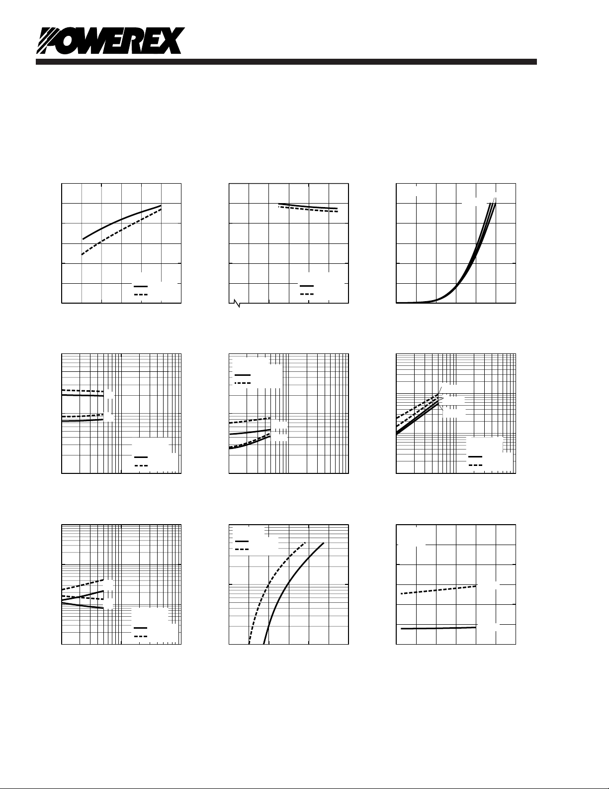
COLLECTOR CURRENT, IC, (AMPERES)
COLLECTOR-EMITTER VOLTAGE V
CE(SAT)
, (VOLTS)
SATURATION VOLTAGE CHARACTERISTICS
(TYPICAL)
0 20 40 60
1.0
0
VD = 15V
2.0
3.0
Tj = 25°C
Tj = 125°C
CONTROL SUPPLY VOLTAGE, VD, (VOLTS)
COLLECTOR-EMITTER SATURATION VOLTAGE,
V
CE(SAT)
, (VOLTS)
COLLECTOR-EMITTER
SATURATON VOLTAGE CHARACTERISTICS
(TYPICAL)
0 13 15 17
1.0
0
2.0
3.0
IC = 50A
Tj = 25°C
Tj = 125°C
COLLECTOR-EMITTER VOLTAGE, V
CE(sat)
, (VOLTS)
OUTPUT CHARACTERISTICS
(TYPICAL)
0 10 20 30
20
0
13
Tj = 25
o
C
40
COLLECTOR CURRENT, I
C
, (AMPERES)
60
15
VD = 17V
COLLECTOR CURRENT, IC, (AMPERES)
SWITCHING TIMES, t
on
, t
off
, (µs)
SWITCHING TIME VS.
COLLECTOR CURRENT (TYPICAL)
10
1
10
1
10
2
10
3
10
0
10
-1
t
on
VCC = 600V
VD = 15V
t
off
Tj = 25°C
Tj = 125°C
CARRIER FREQUENCY, fC, (kHz)
CIRCUIT CURRENT, I
D
, (mA)
CIRCUIT CURRENT VS.
CARRIER FREQUENCY
0 10 20 30
50
0
VD = 15V
100
150
T
j
= 25°C
P-SIDE
N-SIDE
DIODE FORWARD VOLTAGE, VEC, (VOLTS)
DIODE FORWARD CURRENT, I
E
, (AMPERES)
DIODE FORWARD CHARACTERISTICS
10
2
10
1
10
0
Tj = 25°C
Tj = 125°C
VD = 15V
0 1.0 2.0 3.0
COLLECTOR CURRENT, IC, (AMPERES)
REVERSE RECOVERY TIME, t
rr
, (µS)
REVERSE RECOVERY CURRENT VS.
COLLECTOR CURRENT (TYPICAL)
10
1
10
1
10
2
10
3
10
-1
10
-2
I
rr
t
rr
VCC = 600V
VD = 15V
Tj = 25°C
Tj = 125°C
10
3
10
1
10
0
REVERSE RECOVERY CURRENT, I
rr
, (AMPERES)
10
0
10
2
COLLECTOR CURRENT, IC, (AMPERES)
SWITCHING ENERGY, P
SW(on)
, P
SW(off)
, (mJ/PULSE)
SWITCHING LOSS
CHARACTERISTICS (TYPICAL)
10
2
10
1
10
2
10
3
10
0
10
1
10
-1
P
SW(off)
P
SW(on)
VCC = 600V
VD = 15V
Tj = 25°C
Tj = 125°C
P
SW(off)
COLLECTOR CURRENT, IC, (AMPERES)
SWITCHING TIMES,
t
c(on)
, t
c(off)
, (µs)
SWITCHING TIME VS.
COLLECTOR CURRENT (TYPICAL)
10
1
10
1
10
2
10
3
10
0
10
-1
VCC = 600V
VD = 15V
Tj = 25°C
Tj = 125°C
t
c(on)
t
c(off)
PM50RVA120
Intellimod™ Module
Three Phase + Brake IGBT Inverter Output
50 Amperes/1200 Volts
Inverter Part
6
Page 8

Powerex, Inc., 200 E. Hillis Street, Youngwood, Pennsylvania 15697-1800 (724) 925-7272
JUNCTION TEMPERATURE, Tj, (°C)
SUPPLY CIRCUIT UNDER VOLTAGE PROTECTION
TRIP RESET LEVEL, UV
t
, UV
r
, (VOLTS)
CONTROL SUPPLY VOLTAGE TRIP-RESET
LEVEL TEMPERATURE DEPENDANCY
(TYPICAL)
20 100 180
11
0
13
15
VD = 15V
UV
t
UV
r
-60
JUNCTION TEMPERATURE, Tj, (°C)
FAULT OUTPUT PULSE WIDTH TRIP LEVEL,
t
FO
(T
j
= 25°C) = 1.0
FAULT OUTPUT PULSE WIDTH VS.
TEMPERATURE (TYPICAL)
20-60 100 180
0.8
0
1.0
1.2
VD = 15V
JUNCTION TEMPERATURE, Tj, (°C)
SHORT CIRCUIT CURRENT TRIP LEVEL (T
j
= 25°C) = 1.0
OVER CURRENT TRIP LEVEL
TEMPERATURE DEPENDENCY (TYPICAL)
20-60 100 180
0.8
0
1.0
1.2
VD = 15V
TIME, (s)
TRANSIENT IMPEDANCE, Z
th(j-c)
,
(NORMALIZED VALUE)
TRANSIENT THERMAL
IMPEDANCE CHARACTERISTICS
(FWDi)
10
1
10
-1
10
0
10
1
10
0
10
-1
10
-2
10
-3
10
-2
10
-3
SINGLE PULSE
STANDARD VALUE = R
th(j-c)D
= 0.70°C/W
TIME, (s)
TRANSIENT IMPEDANCE, Z
th(j-c)
,
(NORMALIZED VALUE)
TRANSIENT THERMAL
IMPEDANCE CHARACTERISTICS
(IGBT)
10
1
10
-1
10
0
10
1
10
0
10
-1
10
-2
10
-3
10
-2
10
-3
SINGLE PULSE
STANDARD VALUE = R
th(j-c)Q
= 0.37°C/W
CONTROL SUPPLY VOLTAGE, VD, (VOLTS)
SHORT CIRCUIT CURRENT TRIP LEVEL, (V
D
= 15V) = 1.0
OVER CURRENT TRIP LEVEL VS.
SUPPLY VOLTAGE (TYPICAL)
0 13 15 17
0.8
0
1.0
1.2
Tj = 25°C
PM50RVA120
Intellimod™ Module
Three Phase + Brake IGBT Inverter Output
50 Amperes/1200 Volts
Inverter Part
7
Page 9
Powerex, Inc., 200 E. Hillis Street, Youngwood, Pennsylvania 15697-1800 (724) 925-7272
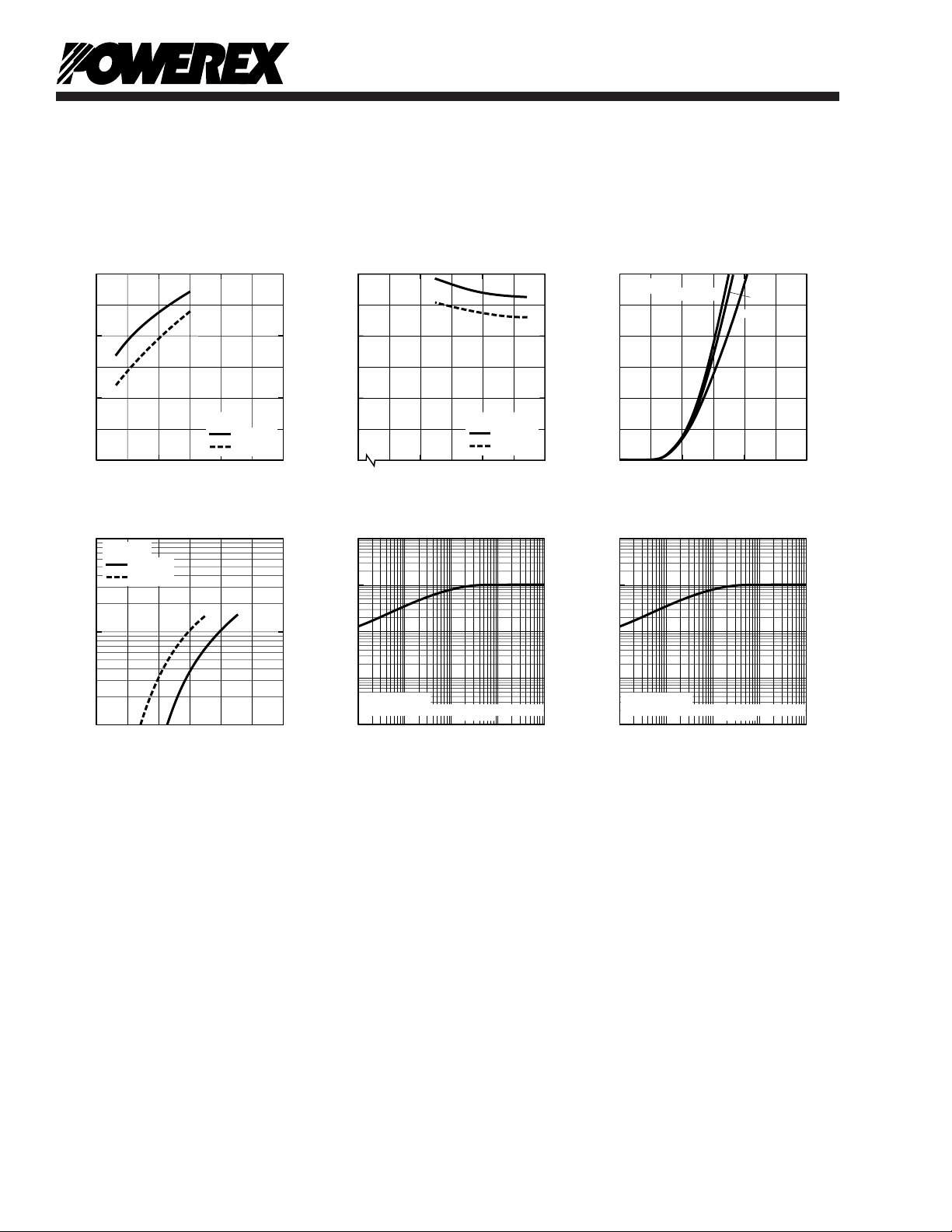
COLLECTOR CURRENT, IC, (AMPERES)
COLLECTOR-EMITTER VOLTAGE V
CE(SAT)
, (VOLTS)
SATURATION VOLTAGE CHARACTERISTICS
(TYPICAL)
0 10 20 30
1.0
0
VD = 15V
2.0
3.0
Tj = 25°C
Tj = 125°C
CONTROL SUPPLY VOLTAGE, VD, (VOLTS)
COLLECTOR-EMITTER SATURATION VOLTAGE,
V
CE(SAT)
, (VOLTS)
COLLECTOR-EMITTER
SATURATON VOLTAGE CHARACTERISTICS
(TYPICAL)
0 13 15 17
0
2.0
1.0
3.0
IC = 15A
Tj = 25°C
Tj = 125°C
COLLECTOR-EMITTER VOLTAGE, V
CE(sat)
, (VOLTS)
OUTPUT CHARACTERISTICS
(TYPICAL)
0 1.5 3.0 4.5
5
0
13
Tj = 25
o
C
10
COLLECTOR CURRENT, I
C
, (AMPERES)
15
15
VD = 17V
DIODE FORWARD VOLTAGE, VEC, (VOLTS)
DIODE FORWARD CURRENT, I
E
, (AMPERES)
DIODE FORWARD CHARACTERISTICS
10
2
10
1
10
0
Tj = 25°C
Tj = 125°C
VD = 15V
0 1.0 2.0 3.0
TIME, (s)
TRANSIENT IMPEDANCE, Z
th(j-c)
,
(NORMALIZED VALUE)
TRANSIENT THERMAL
IMPEDANCE CHARACTERISTICS
(IGBT)
10
1
10
-1
10
0
10
1
10
0
10
-1
10
-2
10
-3
10
-2
10
-3
SINGLE PULSE
STANDARD VALUE = R
th(j-c)Q
= 0.93°C/W
TIME, (s)
TRANSIENT IMPEDANCE, Z
th(j-c)
,
(NORMALIZED VALUE)
TRANSIENT THERMAL
IMPEDANCE CHARACTERISTICS
(FWDi)
10
1
10
-1
10
0
10
1
10
0
10
-1
10
-2
10
-3
10
-2
10
-3
SINGLE PULSE
STANDARD VALUE = R
th(j-c)D
= 1.50°C/W
PM50RVA120
Intellimod™ Module
Three Phase + Brake IGBT Inverter Output
50 Amperes/1200 Volts
Brake Part
8
 Loading...