

Page 1

6121 Baker Road,
Suite 108
Minnetonka, MN 55345
www.chtechnology.com
Phone (952) 933-6190
Fax (952) 933-6223
1-800-274-4284
Thank you for downloading this document from C&H Technology, Inc.
Please contact the C&H Technology team for the following questions -
Technical
Application
Assembly
Availability
Pricing
Phone – 1-800-274-4284
E-Mail – sales@chtechnology.com
www.chtechnology.com - SPECIALISTS IN POWER ELECTRONIC COMPONENTS AND ASSEMBLIES - www.chtechnology.com
Page 2
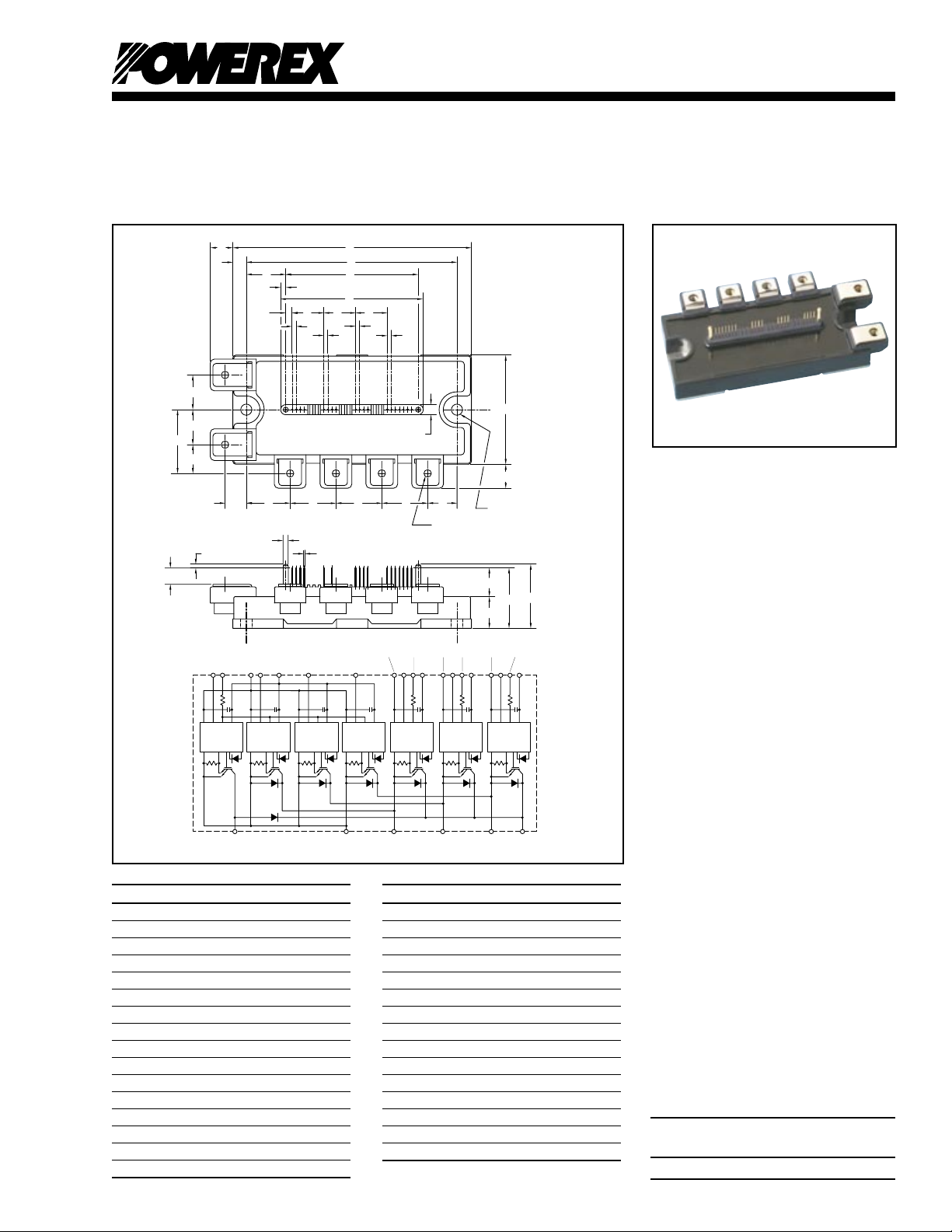
PM50RLA120
19 FO
17 VN
14 VN1
11 WP
8 VVP1
2 U
FO
6 V
FO
5 VVPC
3 UP
7 VP
9 VWPC
10 WFO
12 VWP1
1 VUPC
4 VUP1
16 UN
15 Br
18
WN
13 V
NC
TERMINAL
CODE
AD
Q
V
Y
Y
W
P A
DE
GF
L
H J
JMJ
K
K
K
K
R U U U
T
S
N
B
AA
C
Z
X
AB
(6 PLACES)
AC
(2 PLACES)
AE AF
AG
(2 PLACES)
N
P
B U V W
1 5 9 1
9
V
CC
SIGND GND
OUT
F
O
IN
OT
V
CC
SIGND GND
OUT
F
O
IN
OT
V
CC
SIGND GND
OUT
F
O
IN
OT
V
CC
SIGND GND
OUT
F
O
IN
OT
PU
Br
VWNB
V
CC
SIGND GND
OUT
F
O
IN
OT
V
CC
SIGND GND
OUT
F
O
IN
OT
V
CC
SIGND GND
OUT
F
O
IN
OT
U
N
F
O
V
NC
W
N
VN1V
N
V
WPC
W
P
W
FO
V
WP1
V
VPC
V
P
V
FO
V
VP1
V
UPC
U
P
U
FO
V
UP1
Powerex, Inc., 200 E. Hillis Street, Youngwood, Pennsylvania 15697-1800 (724) 925-7272
Dimensions Inches Millimeters
S 0.46 11.75
T 0.59 15.0
U 0.91 23.0
V 0.57 14.5
W 1.26 32.0
X 1.22 31.0
Y 0.69 17.5
Z 1.14 29.0
AA 0.51 13.0
AB M5 Metric M5
AC 0.22 Dia. Dia. 5.5
AD 0.28 7.0
AE 0.08 2.0
AF 0.02 Sq. Sq. 0.5
AG 0.10 Dia. Dia. 2.5
Outline Drawing and Circuit Diagram
Dimensions Inches Millimeters
A 4.72 120.0
B 2.17 55.0
C 0.63 16.0
D 4.17 106.0
E 0.28 7.0
F 0.78 19.75
G 2.62 66.5
H 0.13 3.25
J 0.63 16.0
K 0.08 2.0
L 0.10 2.5
M 2.81 71.5
N 0.20 5.0
P 0.43 11.0
Q 0.42 10.75
R 0.87 22.0
Intellimod™ L-Series
Three Phase
IGBT Inverter + Brake
50 Amperes/1200 Volts
Description:
Powerex Intellimod™ Intelligent
Power Modules are isolated base
modules designed for power
switching applications operating
at frequencies to 20kHz. Built-in
control circuits provide optimum
gate drive and protection for the
IGBT and free-wheel diode
power devices.
Features:
£ Complete Output Power
Circuit
£ Gate Drive Circuit
£ Protection Logic
– Short Circuit
– Over Temperature
Using On-chip
Temperature Sensing
– Under Voltage
£ Low Loss Using 5th
Generation IGBT Chip
Applications:
£ Inverters
£ UPS
£ Motion/Servo Control
£ Power Supplies
Ordering Information:
Example: Select the complete
part number from the table below
-i.e. PM50RLA120 is a 1200V,
50 Ampere Intellimod™ Intelligent
Power Module.
Type Current Rating V
Amperes Volts (x 10)
PM 50 120
CES
1
Page 3

Powerex, Inc., 200 E. Hillis Street, Youngwood, Pennsylvania 15697-1800 (724) 925-7272
PM50RLA120
Intellimod™ L-Series
Three Phase IGBT Inverter + Brake
50 Amperes/1200 Volts
Absolute Maximum Ratings, Tj = 25°C unless otherwise specified
Characteristics Symbol PM50RLA120 Units
Power Device Junction Temperature Tj -20 to 150 °C
Storage Temperature T
-40 to 125 °C
stg
Mounting Torque, M5 Mounting Screws — 31 in-lb
Mounting Torque, M5 Main Terminal Screws — 31 in-lb
Module Weight (Typical) — 380 Grams
Supply Voltage, Surge (Applied between P - N) V
Self-protection Supply Voltage Limit (Short Circuit protection Capability)* V
CC(surge)
CC(prot.)
Isolation Voltage, AC 1 minute, 60Hz Sinusoidal V
*VD = 13.5 ~ 16.5V, Inverter Part, Tj = 125°C
1000 Volts
800 Volts
2500 Volts
ISO
IGBT Inverter Sector
Collector-Emitter Voltage (VD = 15V, V
Collector Current (TC = 25°C) ±IC 50 Amperes
Peak Collector Current (TC = 25°C) ±ICP 100 Amperes
Collector Dissipation (TC = 25°C) PC 369 Watts
= 15V) V
CIN
1200 Volts
CES
IGBT Brake Sector
Collector-Emitter Voltage (VD = 15V, V
Collector Current (TC = 25°C) ±IC 25 Amperes
Peak Collector Current (TC = 25°C) ±ICP 50 Amperes
Collector Dissipation (TC = 25°C) PC 267 Watts
Diode Rated DC Reverse Voltage (TC = 25°C) V
Diode Forward Current IF 25 Amperes
= 15V) V
CIN
1200 Volts
CES
1200 Volts
R(DC)
Control Sector
Supply Voltage (Applied between V
UP1-VUPC
Input Voltage (Applied between UP-V
Fault Output Supply Voltage VFO 20 Volts
(Applied between UFO-V
UPC
, VFO-V
VPC
Fault Output Current (UFO, VFO, WFO, FO Terminals) IFO 20 mA
UPC
, V
, VP-V
, WFO-V
VP1-VVPC
, WP-V
VPC
, FO-VNC)
WPC
, V
WP1-VWPC
, UN- VN- WN-Br-VNC) V
WPC
, VN1-VNC) VD 20 Volts
20 Volts
CIN
2
Page 4

Powerex, Inc., 200 E. Hillis Street, Youngwood, Pennsylvania 15697-1800 (724) 925-7272
Y
BOTTOM VIEW
X
PM50RLA120
Intellimod™ L-Series
Three Phase IGBT Inverter + Brake
50 Amperes/1200 Volts
Electrical and Mechanical Characteristics, Tj = 25°C unless otherwise specified
Characteristics Symbol Test Conditions Min. Typ. Max. Units
IGBT Inverter Sector
Collector-Emitter Cutoff Current I
VCE = V
Diode Forward Voltage VEC -IC = 50A, V
Collector-Emitter Saturation Voltage V
Tj = 25°C
VD = 15V, V
Tj = 125°C
Inductive Load Switching Times ton 0.5 1.0 2.5 µs
trr VD = 15V, V
t
t
t
VCE = V
CES
VD = 15V, V
CE(sat)
VCC = 600V, IC = 50A — 0.4 1.0 µs
C(on)
Tj = 125°C — 2.0 3.0 µs
off
— 0.7 1.2 µs
C(off)
, VD = 15V, Tj = 25°C — — 1.0 mA
CES
, VD = 15V, Tj = 125°C — — 10 mA
CES
= 15V, VD = 15V — 2.5 3.5 Volts
CIN
= 0V, IC = 50A, — 1.8 2.3 Volts
CIN
= 0V, IC = 50A, — 1.9 2.4 Volts
CIN
= 0 15V — 0.5 0.8 µs
CIN
IGBT Brake Sector
Collector-Emitter Cutoff Current I
VCE = V
Diode Forward Voltage VFM IF = 25A — 2.5 3.5 Volts
Collector-Emitter Saturation Voltage V
Tj = 25°C
VD = 15V, V
Tj = 125°C
TC (Base Plate) Measurement Point
Arm UP VP WP UN VN WN Br
Axis IGBT FWDi IGBT FWDi IGBT FWDi IGBT FWDi IGBT FWDi IGBT FWDi IGBT FWDi
X 28.3 28.4 65.0 64.9 86.9 86.9 39.3 39.2 54.0 54.1 76.0 76.1 17.9 19.3
Y -7.7 1.5 -7.7 1.5 -7.7 1.5 5.7 -3.5 5.7 -3.5 5.7 -3.5 -10.5 4.3
VCE = V
CES
VD = 15V, V
CE(sat)
, VD = 15V, Tj = 25°C — — 1.0 mA
CES
, VD = 15V, Tj = 125°C — — 10 mA
CES
= 0V, IC = 25A, — 1.8 2.3 Volts
CIN
= 0V, IC = 25A, — 1.9 2.4 Volts
CIN
3
Page 5

Powerex, Inc., 200 E. Hillis Street, Youngwood, Pennsylvania 15697-1800 (724) 925-7272
PM50RLA120
Intellimod™ L-Series
Three Phase IGBT Inverter + Brake
50 Amperes/1200 Volts
Electrical and Mechanical Characteristics, Tj = 25°C unless otherwise specified
Characteristics Symbol Test Conditions Min. Typ. Max. Units
Control Sector
Short Circuit Trip Level SC Inverter Part 100 — — Amperes
(-20°C ≤ Tj ≤ 125°C, VD = 15V) Brake Part 50 — — Amperes
Short Circuit Current Delay Time t
Over Temperature Protection OT Trip Level 135 145 155 °C
(Detect Tj of IGBT Chip) OTR Reset Level — 125 — °C
Supply Circuit Under-voltage Protection UV Trip Level 11.5 12.0 12.5 Volts
(-20 ≤ Tj ≤ 125°C) UVR Reset Level — 12.5 — Volts
Circuit Current ID VD = 15V, V
VD = 15V, V
Input ON Threshold Voltage V
Input OFF Threshold Voltage V
Fault Output Current* I
I
Fault Output Pulse Width* tFO VD = 15V 1.0 1.8 — ms
*Fault output is given only when the internal SC, OT and UV protections schemes of either upper or lower devide operate to protect it.
VD = 15V — 0.2 — µs
off(SC)
= 15V, VN1-VNC — 20 30 mA
CIN
Applied between UP-V
th(on)
VP-V
th(off)
VD = 15V, V
FO(H)
VD = 15V, V
FO(L)
VPC
, WP-V
= 15V, V
CIN
WPC
XP1-VXPC
UPC
, UN- VN- WN-Br-VNC 1.7 2.0 2.3 Volts
= 15V — — 0.01 mA
CIN
= 15V — 10 15 mA
CIN
— 5 10 mA
, 1.2 1.5 1.8 Volts
Thermal Characteristics, Tj = 25°C unless otherwise specified
Characteristic Symbol Condition Min. Typ. Max. Units
Junction to Case Thermal Resistance R
Inverter Part R
Junction to Case Thermal Resistance R
Brake Part R
Contact Thermal Resistance R
IGBT (Per 1/6 Module) — — 0.26 °C/Watt
th(j-c)Q
FWDi (Per 1/6 Module) — — 0.39 °C/Watt
th(j-c)D
IGBT — — 0.36 °C/Watt
th(j-c)Q
FWDi — — 0.60 °C/Watt
th(j-c)D
Case to Fin Per Module, — — 0.038 °C/Watt
th(c-f)
Thermal Grease Applied
Recommended Conditions for Use
Characteristic Symbol Condition Value Units
Supply Voltage VCC Applied across P-N Terminals ≤800 Volts
Control Supply Voltage** VD Applied between V
V
Input ON Voltage V
Input OFF Voltage V
PWM Input Frequency f
Arm Shoot-through Blocking Time t
** With ripple satisfying the following conditions: dv/dt swing ≤ ±5V/µs, Variation ≤ 2V peak to peak.
Applied between UP-V
CIN(on)
VP-V
CIN(off)
— ≤20 kHz
PWM
Input Signal ≥2.5 µs
DEAD
VP1-VVPC
VPC
, V
WP1-VWPC, VN1-VNC
, WP-V
, UN- VN- WN-Br-VNC ≥9.0 Volts
WPC
UP1-VUPC
, 15.0 ± 1.5 Volts
, ≤0.8 Volts
UPC
4
Page 6

Powerex, Inc., 200 E. Hillis Street, Youngwood, Pennsylvania 15697-1800 (724) 925-7272
VCC = 600V
VD = 15V
INDUCTIVE LOAD
Tj = 25°C
Tj = 125°C
VCC = 600V
VD = 15V
Tj = 25°C
Tj = 125°C
VCC = 600V
VD = 15V
Tj = 25°C
Tj = 125°C
VCC = 600V
VD = 15V
INDUCTIVE LOAD
Tj = 25°C
Tj = 125°C
EMITTER CURRENT, IE, (AMPERES)
REVERSE RECOVERY CURRENT, I
rr
, (AMPERES)
10
2
10
0
10
1
10
1
10
0
10
2
10
0
10
0
10
1
10
-1
10
-2
10
2
EMITTER CURRENT, IE, (AMPERES)
REVERSE RECOVERY TIME, t
rr
, (µs)
COLLECTOR CURRENT, IC, (AMPERES)
SWITCHING LOSS, E
SW(on)
, (mJ/PULSE)
10
2
10
1
10
0
10
1
10
0
10
-1
10
2
10
2
10
1
10
0
10
1
10
0
10
-1
10
2
SWITCHING LOSS (ON) VS.
COLLECTOR CURRENT
(TYPICAL - INVERTER PART)
COLLECTOR CURRENT, IC, (AMPERES)
SWITCHING LOSS, E
SW(off)
, (mJ/PULSE)
SWITCHING LOSS (OFF) VS.
COLLECTOR CURRENT
(TYPICAL - INVERTER PART)
REVERSE RECOVERY CHARACTERISTICS
(TYPICAL - INVERTER PART)
EMITTER-COLLECTOR VOLTAGE, VEC, (VOLTS)
EMITTER CURRENT, I
E
, (AMPERES)
FREE-WHEEL DIODE
FORWARD CHARACTERISTICS
(TYPICAL - INVERTER PART)
0 2.0 2.51.51.00.5
10
2
10
1
10
0
VD = 15V
Tj = 25°C
Tj = 125°C
COLLECTOR-CURRENT, IC, (AMPERES)
COLLECTOR-EMITTER
SATURATION VOLTAGE,
V
CE(sat)
, (VOLTS)
COLLECTOR-EMITTER
SATURATION VOLTAGE CHARACTERISTICS
(TYPICAL - INVERTER PART)
0 40 7050 60
VD = 15V
Tj = 25°C
Tj = 125°C
302010
2.0
1.5
1.0
0.5
0
TIME, (s)
TRANSIENT THERMAL
IMPEDANCE CHARACTERISTICS
(IGBT & FWDi - INVERTER PART)
10
1
10
-1
10
-2
10
-3
10
0
10
1
10
0
10
-1
10
-3
10
-2
Z
th
= R
th
• (NORMALIZED VALUE)
Single Pulse
TC = 25°C
Per Unit Base =
R
th(j-c)
=
0.34°C/W
(IGBT)
R
th(j-c)
=
0.51°C/W
(FWDi)
NORMALIZED TRANSIENT THERMAL IMPEDANCE, Z
th(j-c')
REVERSE RECOVERY CHARACTERISTICS
(TYPICAL - INVERTER PART)
PM50RLA120
Intellimod™ L-Series
Three Phase IGBT Inverter + Brake
50 Amperes/1200 Volts
5
Page 7

Powerex, Inc., 200 E. Hillis Street, Youngwood, Pennsylvania 15697-1800 (724) 925-7272
PM50RLA120
Intellimod™ L-Series
Three Phase IGBT Inverter + Brake
50 Amperes/1200 Volts
6
 Loading...