

Page 1

6121 Baker Road,
Suite 108
Minnetonka, MN 55345
www.chtechnology.com
Phone (952) 933-6190
Fax (952) 933-6223
1-800-274-4284
Thank you for downloading this document from C&H Technology, Inc.
Please contact the C&H Technology team for the following questions -
Technical
Application
Assembly
Availability
Pricing
Phone – 1-800-274-4284
E-Mail – sales@chtechnology.com
www.chtechnology.com - SPECIALISTS IN POWER ELECTRONIC COMPONENTS AND ASSEMBLIES - www.chtechnology.com
Page 2

PM100RSD060
Powerex, Inc., 200 Hillis Street, Youngwood, Pennsylvania 15697-1800 (724) 925-7272
A
B
R
AC
Q
BP
M
M
N
N
P
TC Measured Point
S
S
78 9 1161234 5
10 12
T
W (TYP)
U
W
V
J H H
E
Z
X (4 PLACES)
AB
S
13
15 17 19
1814 16
C
D
U
10.
1. V
3. U
5.
6.OVF
7.
8.
11.
P
W
UPC
12.
V
UF2.
VV4.
V
V
VWF9.
WP1
O
V
NC
P
13.
UP1
N1
V
14.
B
VPC
R
15.
U
N
16.
V
P
N
17.
VP1
WPC
N
W
18.
F
O
19.
O
Y (6 PLACES)
AA
AD
F G
K
L
K
V
N
N1
NC
R
O
F
B
Rfo
O
CC
IN
F
V
GND
I
S
OUT
GND
B
N
V
V
W
V
O
O
CC
IN
GND
GND
CC
IN
F
F
V
V
GND
I
S
OUT
GND
GND
TEMP
I
S
OUT
GND
TH
NWVUP
FO
WPC
WP1
N
U
O
CC
IN
F
V
I
S
OUT
VPC
W
WP
V
VFOV
Rfo
O
CC
IN
F
V
GND
GND
I
S
OUT
GND
GND
FO
UPC
UP1
VP1
U
UP
V
V
V
V
VP
Rfo
Rfo
O
O
CC
IN
CC
IN
F
F
V
V
GND
I
I
S
S
OUT
OUT
GND
Outline Drawing and Circuit Diagram
Dimensions Inches Millimeters
A 4.33±0.04 110.0±1.0
B 3.74±0.02 95.0±0.5
C 3.50±0.04 89.0±1.0
D 2.91±0.02 74.0±0.5
E 2.62 66.44
F 1.28 32.6
G 1.24 31.6
H 1.02 26.0
J 0.94 24.0
K 0.87 +0.04/-0.02 22.0 +1.0/-0.5
L 0.84 21.2
M 0.79 20.0
N 0.69 17.5
P 0.02±0.01 0.5±0.3
Dimensions Inches Millimeters
Q 0.08±0.02 2.0±0.5
R 0.670 17.02
S 0.39 10.0
T 0.08 2.0
U 0.39 10.0
V 0.16 4.0
W 0.24 Rad. Rad. 6.0
X 0.217 Dia. M5.5
Y 0.197 M5
Z 0.2 Sq. Sq. 0.5
AA 0.10 2.54
AB 0.18 4.5
AC 0.13 3.22
AD 0.06 1.6
Intellimod™ Module
Three Phase + Brake
IGBT Inverter Output
100 Amperes/600 Volts
Description:
Powerex Intellimod™ Intelligent
Power Modules are isolated base
modules designed for power
switching applications operating
at frequencies to 20kHz. Built-in
control circuits provide optimum
gate drive and protection for the
IGBT and free-wheel diode
power devices.
Features:
□ Complete Output Power
Circuit
□ Gate Drive Circuit
□ Protection Logic
– Short Circuit
– Over Current
– Over Temper ature
– Under V oltage
□ Low Loss Using 4th Generation
IGBT Chip
Applications:
□ Inverters
□ UPS
□ Motion/Servo Control
□ Power Supplies
Ordering Information:
Example: Select the complete
part number from the table below
-i.e. PM100RSD060 is a 600V,
100 Ampere Intellimod™ Intelligent
Power Module.
Type Current Rating V
Amperes Volts (x 10)
PM 100 60
CES
1
Page 3

Powerex, Inc., 200 Hillis Street, Youngwood, Pennsylvania 15697-1800 (724) 925-7272
PM100RSD060
Intellimod™ Module
Three Phase + Brake IGBT Inverter Output
100 Amperes/600 Volts
Absolute Maximum Ratings, Tj = 25°C unless otherwise specified
Characteristics Symbol PM100RSD060 Units
Power Device Junction Temperature T
Storage Temperature T
Case Operating Temperature T
j
stg
C
-20 to 150 °C
-40 to 125 °C
-20 to 100 °C
Mounting Torque, M5 Mounting Screws — 31 in-lb
Mounting Torque, M5 Main Terminal Screws — 31 in-lb
Module Weight (T ypical) — 560 Grams
Supply Voltage Protected by OC and SC (VD = 13.5 - 16.5V, Inverter Part) Tj = 125°CV
CC(prot.)
Isolation Voltage, AC 1 minute, 60Hz Sinusoidal V
ISO
400 Volts
2500 Volts
IGBT Inverter Sector
Collector-Emitter Voltage (VD = 15V, V
Collector Current, ± (TC = 25°C) I
Peak Collector Current, ± (TC = 25°C) I
Supply Voltage (Applied between P - N) V
Supply Voltage, Surge (Applied between P - N) V
Collector Dissipation (TC = 25°C) P
= 15V) V
CIN
CES
C
CP
CC
CC(surge)
C
600 Volts
100 Amperes
200 Amperes
400 Volts
500 Volts
328 Watts
IGBT Brake Sector
Collector-Emitter Voltage (VD = 15V, V
Collector Current, ± (TC = 25°C) I
Peak Collector Current, ± (TC = 25°C) I
FWDi Rated DC Reverse Voltage (TC = 25°C) V
FWDi Forward Current (TC = 25°C) I
Collector Dissipation (TC = 25°C) P
= 15V) V
CIN
CES
C
CP
R(DC)
F
C
600 Volts
30 Amperes
60 Amperes
600 Volts
30 Amperes
176 Watts
Control Sector
Supply Voltage Applied between (V
Input Voltage Applied between (UP-V
UP1-VUPC
UPC
Fault Output Supply Voltage (Applied between FO and VC)V
Fault Output Current (UFO, VFO, WFO, FO)I
, VP-V
, V
VP1-VVPC
VPC
, WP-V
, V
WP1-VWPC
, UN- VN- WN-Br-VNC)V
WPC
, VN1-VNC)V
D
CIN
FO
FO
20 Volts
20 Volts
20 Volts
20 mA
2
Page 4

Powerex, Inc., 200 Hillis Street, Youngwood, Pennsylvania 15697-1800 (724) 925-7272
PM100RSD060
Intellimod™ Module
Three Phase + Brake IGBT Inverter Output
100 Amperes/600 Volts
Electrical and Mechanical Characteristics, Tj = 25°C unless otherwise specified
Characteristics Symbol Test Conditions Min. Typ. Max. Units
IGBT Inverter Sector
Collector Cutoff Current I
Diode Forward Voltage V
Collector-Emitter Saturation Voltage V
Inductive Load Switching Times t
CES
EC
CE(sat)
on
t
rr
t
C(on)
t
off
t
C(off)
VCE = V
, Tj = 25°C, ——1.0 mA
CES
VD = 15V
VCE = V
, Tj = 125°C, ——10 mA
CES
VD = 15V
-IC = 100A, VD = 15V, V
VD = 15V, V
= 0V, IC = 100A, — 1.7 2.3 Volts
CIN
= 15V — 2.2 3.3 Volts
CIN
Tj = 25°C
VD = 15V, V
= 0V, IC = 100A, — 1.7 2.3 Volts
CIN
Tj = 125°C
0.8 1.2 2.4 µS
VD = 15V, V
= 0 ~ 15V — 0.15 0.3 µS
CIN
VCC = 300V, IC = 100A — 0.4 1.0 µS
Tj = 125°C — 2.4 3.3 µS
— 0.6 1.2 µS
IGBT Brake Sector
Collector Cutoff Current I
FWDi Forward Voltage V
Collector-Emitter Saturation Voltage V
CES
FM
CE(sat)
VCE = V
VCE = V
VD = 15V, V
VD = 15V, V
, Tj = 25°C, ——1.0 mA
CES
VD = 15V
, Tj = 125°C, ——10 mA
CES
VD = 15V
-IF = 30A — 2.5 3.5 Volts
= 0V, IC = 30A, — 1.8 2.5 Volts
CIN
Tj = 25°C
= 0V, IC = 30A, — 1.9 2.6 Volts
CIN
Tj = 125°C
3
Page 5

Powerex, Inc., 200 Hillis Street, Youngwood, Pennsylvania 15697-1800 (724) 925-7272
PM100RSD060
Intellimod™ Module
Three Phase + Brake IGBT Inverter Output
100 Amperes/600 Volts
Electrical and Mechanical Characteristics, Tj = 25°C unless otherwise specified
Characteristics Symbol Test Conditions Min. Typ. Max. Units
Control Sector
Over Current Trip Level Inverter Part OC Tj = -20°C ——520 Amperes
(VD = 15V) Tj = 25°C 264 311 430 Amperes
Tj = 125°C 158 ——Amperes
Over Current Trip Level Brake Part OC -20°C ≤ Tj ≤ 125°C, VD = 15V 39 53 — Amperes
Short Circuit Trip Level Inverter Part SC -20°C ≤ Tj ≤ 125°C, VD = 15V — 360 — Amperes
Short Circuit Trip Level Brake Part — 79 — Amperes
Over Current Delay Time t
off(OC)
Over Temperature Protection (VD = 15V) OT Trip Level 111 118 125 °C
(Lower Arm) OT
R
Supply Circuit Under Voltage Protection UV Trip Level 11.5 12.0 12.5 Volts
(-20 ≤ Tj ≤ 125°C) UV
Circuit Current I
R
D
VD = 15V, V
VD = 15V, V
Input ON Threshold Voltage V
Input OFF Threshold Voltage V
Fault Output Current* I
Minimum Fault Output Pulse Width* t
*Fault output is given only when the internal OC, SC, OT and UV protections schemes of either upper or lower devide operate to protect it.
CIN(on)
CIN(off)
FO(H)
I
FO(L)
FO
UP, VP, WP, UN, VN, W
VD = 15V — 10 — µS
Reset Level — 100 — °C
Reset Level — 12.5 — Volts
= 15V, VN1-V
CIN
= 15V, V
CIN
NC
XP1-VXPC
— 44 60 mA
— 13 18 mA
Applied between 1.2 1.5 1.8 Volts
1.7 2.0 2.3 Volts
VD = 15V, V
VD = 15V, V
N, Br-VNC
= 15V ——0.01 mA
CIN
= 15V — 10 15 mA
CIN
VD = 15V 1.0 1.8 — mS
4
Page 6

Powerex, Inc., 200 Hillis Street, Youngwood, Pennsylvania 15697-1800 (724) 925-7272
PM100RSD060
Intellimod™ Module
Three Phase + Brake IGBT Inverter Output
100 Amperes/600 Volts
Thermal Characteristics
Characteristic Symbol Condition Min. Typ. Max. Units
Junction to Case Thermal Resistance R
Inverter Part R
R
R
Junction to Case Thermal Resistance R
Brake Part R
R
R
Contact Thermal Resistance R
th(j-c)Q
th(j-c)F
th(j-c´)Q
th(j-c´)F
th(j-c)Q
th(j-c)F
th(j-c´)Q
th(j-c´)F
th(c-f)
Each IGBT ——0.38 °C/Watt
Each FWDi ——0.70 °C/Watt
Each IGBT* —— 0.23** °C/Watt
Each FWDi* —— 0.36** °C/Watt
Each IGBT ——0.71 °C/Watt
Each FWDi ——1.66 °C/Watt
Each IGBT* —— 0.45** °C/Watt
Each FWDi* —— 0.96** °C/Watt
Case to Fin Per Module, —— 0.027 °C/Watt
Thermal Grease Applied
*TC measured point is just under chip.
**If you use this value, R
should be measured just under the chips.
th(f-a)
Recommended Conditions for Use
Characteristic Symbol Condition Value Units
Supply Voltage V
Control Supply Voltage*** V
Input ON Voltage V
Input OFF Voltage V
PWM Input Frequency f
Minimum Dead Time t
*** With ripple satisfying the following conditions: dv/dt swing ≤ ±5V/µs, Variation ≤ 2V peak to peak.
CC
D
CIN(on)
CIN(off)
PWM
DEAD
Applied across P-N Terminals 0 ~ 400 Volts
Applied between V
VN1-VNC, V
VP1-VVPC
UP1-VUPC
, V
, 15 ± 1.5 Volts
WP1-VWPC
Applied between 0 ~ 0.8 Volts
UP, VP, WP, U
N, VN, WN, Br-VNC
4.0 ~ VDVolts
Using Application Circuit 5 ~ 20 kHz
Input Signal ≥ 2.5 µS
5
Page 7
Powerex, Inc., 200 Hillis Street, Youngwood, Pennsylvania 15697-1800 (724) 925-7272
PM100RSD060
Intellimod™ Module
Three Phase + Brake IGBT Inverter Output
100 Amperes/600 Volts
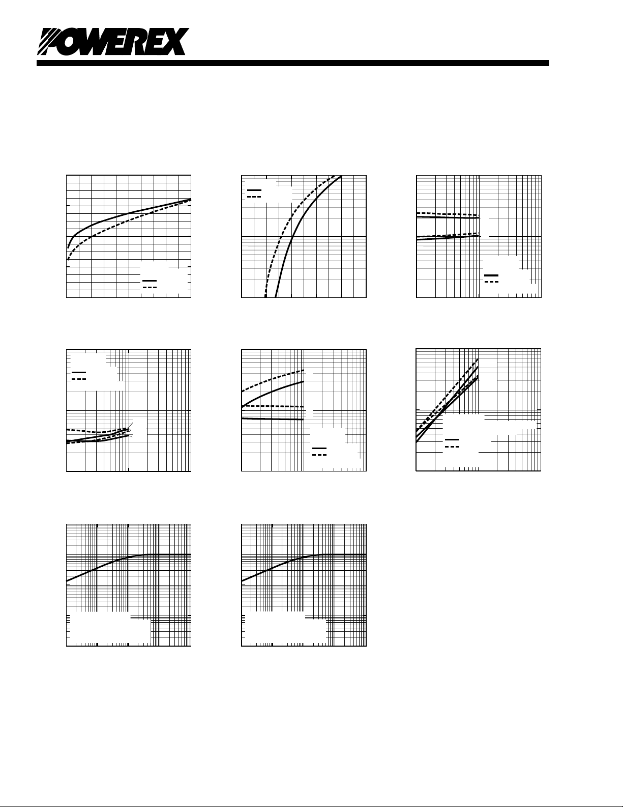
SATURATION VOLTAGE
CHARACTERISTICS (TYPICAL)
(INVERTER PART)
2.0
1.5
, (VOLTS)
CE(sat)
1.0
0.5
SATURATION VOLTAGE, V
0
0 20 10040 60 80
COLLECTOR CURRENT, IC, (AMPERES)
SWITCHING TIME VS.
COLLECTOR CURRENT (TYPICAL)
1
10
VCC = 300V
= 15V
V
D
o
= 25
T
C
j
, (µs)
INDUCTIVE LOAD
c(off)
, t
c(on)
0
10
SWITCHING TIMES, t
-1
10
1
10
1
10
o
= 125
C
T
j
COLLECTOR CURRENT, IC, (AMPERES)
TRANSIENT THERMAL
IMPEDANCE CHARACTERISTICS
(IGBT & FWDi - INVERTER PART)
10
2
t
c(off)
t
c(on)
t
c(off)
VD = 15V
= 0V
V
CIN
T
j
T
j
= 25oC
= 125oC
DIODE FORWARD CHARACTERISTICS
(INVERTER PART)
2
10
= 15V
V
D
Tj = 25oC
= 125oC
T
j
, (AMPERES)
C
1
10
DIODE CURRENT, -I
0
10
0 1.0 2.5
0.5 1.5 2.0
DIODE FORWARD VOLTAGE, VEC, (VOLTS)
REVERSE RECOVERY CURRENT VS.
COLLECTOR CURRENT (TYPICAL)
0
10
I
, (µS)
rr
-1
10
REVERSE RECOVERY TIME, t
-2
3
10
10
1
10
COLLECTOR CURRENT, IC, (AMPERES)
TRANSIENT THERMAL
IMPEDANCE CHARACTERISTICS
10
(IGBT & FWDi - BRAKE PART)
1
rr
t
rr
VCC = 300V
= 15V
V
D
INDUCTIVE LOAD
2
10
T
= 25oC
j
= 125oC
T
j
2
10
1
10
0
10
3
10
1
10
, (µs)
off
, t
on
0
10
SWITCHING TIMES, t
-1
10
10
1
10
, (AMPERES)
rr
(mJ/PULSE)
SW
0
10
SWITCHING LOSS, E
REVERSE RECOVERY CURRENT, I
-1
10
1
10
SWITCHING TIME VS.
COLLECTOR CURRENT (TYPICAL)
t
off
t
on
VCC = 300V
= 15V
V
D
= 25
T
j
= 125
T
j
INDUCTIVE LOAD
1
COLLECTOR CURRENT, IC, (AMPERES)
2
10
SWITCHING LOSS CHARACTERISTICS
E
sw(off)
E
sw(on)
CONDITIONS:
HALF-BRIDGE INDUCTIVE LOAD
SWITCHING OPERATION
V
CC
V
GE
COLLECTOR CURRENT, IC, (AMPERES)
T
j
T
j
= 300V
= ±15V
= 25
= 125
10
o
C
o
C
2
o
C
o
C
3
10
3
10
0
10
, (NORMALIZED VALUE)
-1
th(j-c)
10
-2
STANDARD VALUE
10
R
R
SINGLE PULSE
-3
10
TRANSIENT IMPEDANCE, Z
-3
10
6
= 0.38oC/W (IGBT)
th(j-c)Q
= 0.70oC/W (FWDi)
th(j-c)Q
-2
10
-1
10
TIME, (s)
0
10
, (NORMALIZED VALUE)
-1
th(j-c)
10
-2
STANDARD VALUE
10
-3
10
TRANSIENT IMPEDANCE, Z
0
10
10
1
10
= 0.71oC/W (IGBT)
R
th(j-c)Q
= 1.66oC/W (FWDi)
R
th(j-c)Q
SINGLE PULSE
-3
10
-2
-1
10
TIME, (s)
0
10
1
10
 Loading...