

Page 1

6121 Baker Road,
Suite 108
Minnetonka, MN 55345
www.chtechnology.com
Phone (952) 933-6190
Fax (952) 933-6223
1-800-274-4284
Thank you for downloading this document from C&H Technology, Inc.
Please contact the C&H Technology team for the following questions -
Technical
Application
Assembly
Availability
Pricing
Phone – 1-800-274-4284
E-Mail – sales@chtechnology.com
www.chtechnology.com - SPECIALISTS IN POWER ELECTRONIC COMPONENTS AND ASSEMBLIES - www.chtechnology.com
Page 2
Powerex, Inc., 173 Pavilion Lane, Youngwood, Pennsylvania 15697 (724) 925-7272 POW-R-BLOK
www.pwrx.com
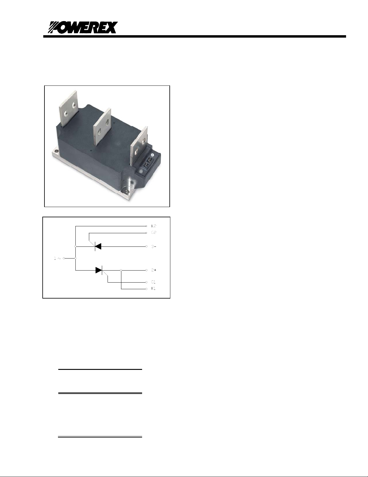
Dual SCR Isolated Module
600 Amperes / Up to 2400 Volts
PD43__06
TM
Ordering Information:
Select the complete eight-digit
module part number from the table
below.
Example: PD432406 is a 2400 Volt,
600A Average Dual SCR Isolated
POW-R-BLOK
Type
PD43
TM
Module
Voltage
Volts (x100)
20
22
24
Current
Amperes
(x100)
06
Description:
Powerex Dual SCR Modules are designed for
use in applications requiring phase control
and isolated packaging. The modules are
isolated for easy mounting with other
components on a common heatsink.
Features:
Electrically Isolated Heatsinking
Compression Bonded Elements
Metal Baseplate
Low Thermal Impedance
for Improved Current Capability
Benefits:
No Additional Insulation
Components Required
Easy Installation
No Clamping Components
Required
Reduce Engineering Time
Applications:
Bridge Circuits
AC & DC Motor Drives
Motor Soft Starters
Battery Supplies
Power Supplies
Large IGBT Circuit Front Ends
Revision Date: 09/28/2009
Page 3

A
Powerex, Inc., 173 Pavilion Lane, Youngwood, Pennsylvania 15697 (724) 925-7272 POW-R-BLOK
www.pwrx.com
Dual SCR Isolated Module
600 Amperes / Up to 2400 Volts
PD43__06
TM
Absolute Maximum Ratings
Characteristics Conditions Symbol Units
Repetitive Peak Forward and Reverse Blocking
Voltage
Non-Repetitive Peak Blocking Voltage
(t < 5 msec)
RMS Current AC Switch Configuration
o
Conduction)
(180
180° Conduction, T
180° Conduction, T
180° Conduction, T
180° Conduction, T
180° Conduction, T
180° Conduction, T
RMS Current Per SCR
o
Conduction)
(180
180° Conduction, T
180° Conduction, T
180° Conduction, T
180° Conduction, T
180° Conduction, T
180° Conduction, T
verage Forward Current Per SCR
o
Conduction)
(180
180° Conduction, T
180° Conduction, T
180° Conduction, T
180° Conduction, T
180° Conduction, T
180° Conduction, T
Peak One Cycle Surge Current, Non-Repetitive
Tj = 25C, Vr = 0
Peak One Cycle Surge Current, Non-Repetitive
Tj = 25C, Vr = Vrrm
Peak One Cycle Surge Current, Non-Repetitive
Tj = 125C, Vr = 0
Peak One Cycle Surge Current, Non-Repetitive
Tj = 125C, Vr = Vrrm
Peak Three Cycle Surge Current, Non-Repetitive 60 Hz, Tj = 125C, Vr = Vrrm I
Peak Ten Cycle Surge Current, Non-Repetitive 60 Hz, Tj = 125C, Vr = Vrrm I
I2t for Fusing for One Cycle
Tj = 125C, Vr = Vrrm
Maximum Rate-of-Rise of On-State Current,
Per JEDEC Standard 397 5.2.2.6 di/dt 400
(Non-Repetitive)
Maximum Rate-of-Rise of On-State Current,
Per JEDEC Standard 397 5.2.2.6 di/dt 150
(Repetitive)
Operating Temperature TJ -40 to +125
Storage Temperature T
Max. Mounting Torque, M6 Mounting Screw 132
Max. Mounting Torque, M10 Terminal Screw 106
Module Weight, Typical 5.33 kg
11.75 lb
V Isolation @ 25C
V
V
=66°C
C
=71°C
C
=76°C
C
=81°C
C
=86°C
C
=90°C
C
=66°C
C
=71°C
C
=76°C
C
=81°C
C
=86°C
C
=90°C
C
=66°C
C
=71°C
C
=76°C
C
=81°C
C
=86°C
C
=90°C
C
60 Hz
50 Hz
60 Hz
50 Hz
60 Hz
50 Hz
60 Hz
50 Hz
8.3 milliseconds
10 milliseconds
& V
DRM
RRM
V
RSM
I
T(RMS)
I
T(RMS)
I
T(RMS)
I
T(RMS)
I
T(RMS)
I
T(RMS)
I
T(RMS)
I
T(RMS)
I
T(RMS)
I
T(RMS)
I
T(RMS)
I
T(RMS)
I
T(AV)
I
T(AV)
I
T(AV)
I
T(AV)
I
T(AV)
I
T(AV)
I
TSM
I
TSM
I
TSM
I
TSM
I
TSM
I
TSM
I
TSM
I
TSM
23,690 A
TSM
18,615 A
TSM
I2t
2
t
I
-40 to +150
stg
V
rms
Up to 2400 V
+ 100V V
RRM
1665
1550
1440
1330
1220
1110
1178
1100
1020
942
864
785
750
700
650
600
550
500
50,890
46,400
33,925
30,935
44,250
40,350
29,500
26,900
3.63 x 10
3.62 x 10
6
6
A
A
A
A
A
A
A
A
A
A
A
A
A
A
A
A
A
A
A
A
A
A
A
A
A
A
2
A
2
A
A/μs
A/μs
°C
°C
in. – Lb.
15
Nm
in. – Lb.
12
Nm
3000 V
Revision Date: 09/28/2009
sec
sec
Page 4

Powerex, Inc., 173 Pavilion Lane, Youngwood, Pennsylvania 15697 (724) 925-7272 POW-R-BLOK
www.pwrx.com
Dual SCR Isolated Module
600 Amperes / Up to 2400 Volts
PD43__06
TM
Electrical Characteristics, TJ=25°C unless otherwise specified
Characteristics Symbol Test Conditions Min. Max.
Repetitive Peak Forward Leakage Current I
Repetitive Peak Reverse Leakage Current I
Peak On-State Voltage VTM
Threshold Voltage, Low-level
Slope Resistance, Low-level
Threshold Voltage, High-level
Slope Resistance, High-level
VTM Coefficients, Full Range
V
V
DRM
RRM
(TO)1
r
T1
(TO)2
r
T2
Up to 2400V, T
Up to 2400V, T
I
=3000A, TJ=125°C
TM
= 125°C, I = 15%I
T
J
=125°C
J
=125°C
J
to πI
T(AV)
T(AV)
= 125°C, I = πI
T
J
T(AV)
to I
TSM
T
= 125°C, I = 50A to 6kA
J
V
= A+ B Ln I +C I + D Sqrt I
TM
100 mA
100 mA
1.75 V
0.869
0.237 V mΩ
1.055
0.175 V mΩ
A =
B =
C =
D =
0.93159
-4.51 E-02
9.95 E-05
1.29 E-02
Units
Minimum dV/dt dV/dt Exponential to 0.67V
T
=125°C, Gate Open
j
Gate Trigger Current IGT
Gate Trigger Voltage VGT
Non-Triggering Gate Voltage V
GDM
T
=25°C, VD=12V
j
T
=25°C, VD=12V
j
T
=125°C, VD= ½ V
j
DRM
DRM
300
V/μs
200 mA
4.5 Volts
0.15 Volts
Holding Current IH 300 mA
Peak Forward Gate Current I
Peak Reverse Gate Voltage V
Maximum Average Gate Power Dissipation P
4.0 Amp
GTM
5 Volts
GRM
16 Watts
GM (AVE)
Thermal Characteristics
Characteristics Symbol
Thermal Resistance, Junction to Case
Thermal Impedance Coefficients
R
J-C
Θ
Z
Θ
J-C
Per Module, both conducting
Per Junction, both conducting
Z
J-C
Θ
+ K
+ K
+ K
Thermal Resistance, Case to Sink Lubricated
R
C-S
Θ
= K1 (1-exp(-t/t1))
(1-exp(-t/t2))
2
(1-exp(-t/t3))
3
(1-exp(-t/t4))
4
K
= 5.04 E-04
1
K2 = 2.31 E-03
K3 = 2.83 E-03
K4 =5.24 E-02
Per Module 0.009
Information presented is based upon manufacturers testing and projected capabilities.
This information is subject to change without notice.
The manufacturer makes no claim as to suitability for use, reliability, capability,
or future availability of this product.
Max. Units
0.029
0.058
t
= 2.47 E-03
1
= 4.42 E-02
t
2
= 1.370
t
3
= 9.668
t
4
°C/W
°C/W
°C/W
Revision Date: 09/28/2009
Page 5

Powerex, Inc., 173 Pavilion Lane, Youngwood, Pennsylvania 15697 (724) 925-7272 POW-R-BLOK
www.pwrx.com
Dual SCR Isolated Module
600 Amperes / Up to 2400 Volts
PD43__06
TM
0.06
0.05
0.04
Maximum Transient Thermal Impedance
(Junction To Case)
4
3.5
3
2.5
Typical On-State Forward Voltage Drop
(Tj = 125C)
2
1.5
1
On-State Voltage - Vt - Volts
0.5
0
10 100 1000 10000 100000
1200
1000
800
600
400
200
Max. Power Dissipation Pe r SC R - W att s_
0
0 100 200 300 400 500 600 700 800
Instantaneous On-State Current - It - Amperes
Maximum On-State Power Dissi p ati on
(Sinusoidal Waveform)
60°
30°
15°
0
CONDUCTION ANGLE
Average On-State Current - It(av) - Amperes
Maximum On-State Power Dissipation
90°
120°
180°
180
360
(Rectangular Waveform)
1600
1400
1200
180°
360°
270°
120°
1000
800
600
30°
15°
60°
90°
400
180
Max. Power Dissipation Per SCR - Watts_
200
0
0
CONDUCTION ANGLE
360
0 200 400 600 800 1000 1200 1400
Average On-State Current - It(av) - Amperes
0.03
0.02
Thermal Impedance - Rjc - °C/W
0.01
0.00
0.001 0.01 0.1 1 10 100
Maximum Allowable Case Temperature
Time - t - Seconds
(Sinusoidal Waveform)
130
120
110
180
100
90
80
Max. Case Temperature - Tcase -°C_
70
60
0 100 200 300 400 500 600 700 800
15°
30°
60°
0
CONDUCTION ANGLE
90°
120°
Average On-State Current - It(av) - Amperes
Maximum Allowable Case Temperature
(Rectangular Waveform)
130
120
110
100
Max. Case Temperature - Tcase -°C_
90
80
70
60
15°
30°
60°
90°
120°
50
180
0
CONDUCTION ANGLE
180°
270°
360
360°
40
0 200 400 600 800 1000 1200 1400
Average On-State Current - It(av) - Amperes
360
180°
Revision Date: 09/28/2009
Page 6

Powerex, Inc., 173 Pavilion Lane, Youngwood, Pennsylvania 15697 (724) 925-7272 POW-R-BLOK
www.pwrx.com
Dual SCR Isolated Module
600 Amperes / Up to 2400 Volts
PD43__06
TM
Revision Date: 09/28/2009
 Loading...