

Page 1
HL, NHL FLAT and HLM, NHLM
Vishay Dale
Wirewound Resistors,
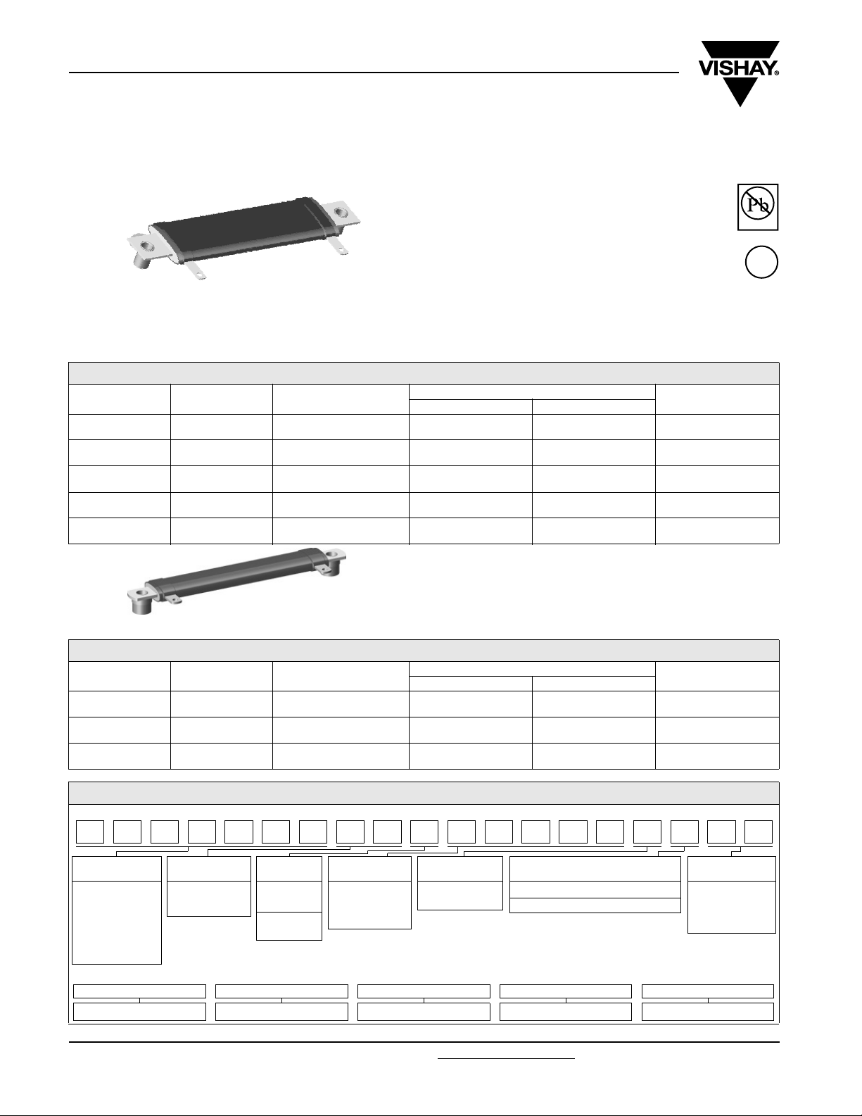
Industrial Power, Flat (HL), Miniature Flat (HLM)
TYPE HL FLAT STYLE
STANDARD ELECTRICAL SPECIFICATIONS
GLOBAL
MODEL
HL024
NHL024
HL035
NHL035
HL055
NHL055
HL070
NHL070
HL095
NHL095
HISTORICAL
MODEL
HL-24
NHL-24
HL-35
NHL-35
HL-55
NHL-55
HL-70
NHL-70
HL-95
NHL-95
POWER RATING P
W
30
40
55
70
95
25 °C
FEATURES
• High temperature silicon coating
• Mounting accommodations ideally suited to
high density packaging
• Self-stacking hardware for horizontal or vertical
placement
• Withstands high vibrations without loosening
• Mounting hardware functions as a heat sink
allowing greater heat dissipation and less
derating of stacked units
• Available in non-inductive styles (type NHL and NHLM)
with Aryton-Perry winding
RESISTANCE RANGE Ω
± 5 % ± 10 %
1.0 - 11K
1.0 - 1.2K
1.0 - 26K
1.0 - 3K
1.0 - 54K
1.0 - 6.8K
1.0 - 77K
1.0 - 9.4K
1.0 - 99.9K
1.0 -12.4K
0.10 - 11K
1.0 - 1.2K
0.10 - 26K
1.0 - 3K
0.10 - 54K
1.0 - 6.8K
0.10 - 77K
1.0 - 9.4K
0.10 - 99.9K
1.0 - 12.4K
WEIGHT (typical)
20.14
30.07
51.25
60.48
76.51
Pb-free
Available
e3
RoHS*
COMPLIANT
g
TYPE HLM MINIATURE FLAT STYLE
STANDARD ELECTRICAL SPECIFICATIONS
GLOBAL
MODEL
HLM010
NHLM010
HLM015
NHLM015
HLM020
NHLM020
HISTORICAL
MODEL
HLM-10
NHLM-10
HLM-15
NHLM-15
HLM-20
NHLM-20
POWER RATING P
W
10
15
20
25 °C
RESISTANCE RANGE Ω
± 5 % ± 10 %
1.0 - 15K
1.0 - 1.8K
1.0 - 26K
1.0 - 3.6K
1.0 - 71K
1.0 - 9.8K
0.10 - 15K
1.0 - 1.8K
0.10 - 26K
1.0 - 3.6K
0.10 - 71K
1.0 - 9.8K
WEIGHT (typical)
g
0.41
0.47
0.74
GLOBAL PART NUMBER INFORMATION
New Global Part Numbering: NHLM01010Z10R00JJ (preferred part number format)
HLM01010Z10R00JJN
GLOBAL
MODEL
NHLM010 09
(See “Standard
Electrical
Specifications”
table above for
additional P/N’s)
Historical Part Number Example: NHLM-10-10Z 10 Ω 5 % J01 (will continue to be accepted)
NHLM-10 10Z 10 Ω 5 % J01
HISTORICAL MODEL TERMINAL/FINISH RESISTANCE VALUE TOLERANCE PACKAGING
* Pb containing terminations are not RoHS compliant, exemptions may apply
www.vishay.com For technical questions, contact: ww2bresistors@vishay.com
72 Revision: 13-Jul-07
TERMINAL
DESIGNATION
10
16
TERMINAL
FINISH
E = Lead
(Pb)-free
Z = Tin/lead
N = Nickel
RESISTANCE
VAL UE
R = Decimal
K = Thousand
10R00 = 10.0 Ω
1K000 = 1 kΩ
TOLERANCE PACKAGING CODE SPECIAL
J = ± 5.0 %
K = ± 10.0 %
* Tin/lead for type “Z”, lead (Pb)-free for type “N”
E = Lead (Pb)-free skin pack
J* = Skin pack (J01)
Document Number: 30209
(Dash Number)
(up to 2 digits)
From 1 - 99
as applicable
Page 2
HL, NHL FLAT and HLM, NHLM
Industrial Power, Flat (HL), Miniature Flat (HLM)
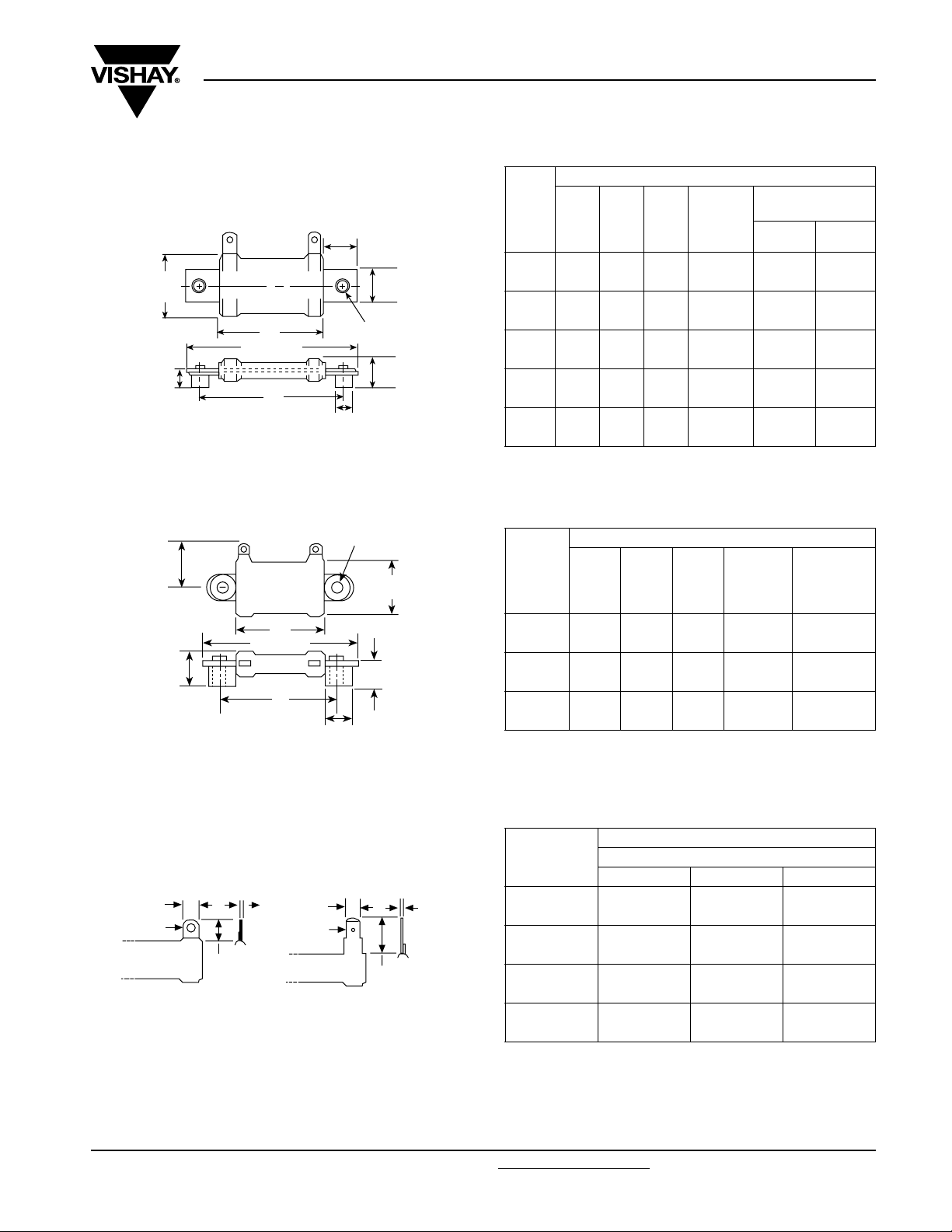
DIMENSIONS in inches [millimeters]
TYPE HL FLAT STYLE
0.625 [15.88]
1.188 [30.16]
max.
A
B
0.438 ± 0.030
[11.11 ± 0.794]
C
TYPE HLM MINIATURE FLAT STYLE
0.126 [3.20] Dia. typ.
0.412
[10.46]
max.
A
B
0.343 [8.71]
max.
C
0.218 [5.54]
Dia. typ.
0.594 [15.08]
0.196 [4.98] Dia. typ.
0.563 ± 0.030
[14.29 ± 0.794]
0.313 [7.94] Dia.
0.375 [9.52]
0.250 [6.35]
Wirewound Resistors,
MODEL
HL024
NHL024
HL035
NHL035
HL055
NHL055
HL070
NHL070
HL095
NHL095
MODEL
HLM010
NHLM010
HLM015
NHLM015
HLM020
NHLM020
± 0.063
[1.59]
1.250 2.500 2.000 0.718
[31.75] [63.50] [50.80] [18.24]
2.000 3.250 2.750 1.468
[50.80] [82.55] [69.85] [37.29]
3.500 4.750 4.250 2.968
[88.90] [120.65] [107.95] [75.39]
4.750 6.000 5.500 4.218
[120.65] [152.40] [139.70] [107.14]
6.000 7.250 6.750 5.468
[152.40] [184.15] [171.45] [138.89]
A
A
± 0.063
[1.59]
B
± 0.063
[1.59]
± 0.063
DIMENSIONS
± 0.031
DIMENSIONS
B
[1.59]
C
[0.79]
TERMINALS
± 0.031
[0.79]
in inches [millimeters]
DISTANCE
BETWEEN
(REF.)
in inches [millimeters]
DISTANCE
C
BETWEEN
TERMINALS
(REF.)
0.750 1.312 1.000 0.406
[19.05] [33.32] [25.40] [10.31]
1.000 1.562 1.250 0.656
[25.40] [39.67] [31.75] [16.66]
2.062 2.625 2.313 1.718
[52.37] [66.68] [58.75] [43.64]
Vishay Dale
TERMINAL
DESIGNATION
STANDARD OPTIONAL
09Z 16N
09Z 16N
09Z 16N
09Z 16N
09Z 16N
STANDARD
TERMINAL
DESIGNATION
10Z
10Z
10Z
TERMINAL DIMENSIONS
DIMENSIONS in inches [millimeters]
DIMENSION
TERMINAL TYPE
TERM 09 TERM 10 TERM 16
0.188 0.125 0.188
[4.76] [3.18] [4.76]
0.500 0.188 0.563
[12.70] [4.76] [14.29]
0.104 0.063 0.050
[2.64] [1.60] [1.27]
0.020 0.020 0.020
[0.51] [0.51] [0.51]
Style 09
and 10
A
C
D
A
C
D
A
B
B
Style 16
B
C
D
TERMINAL FINISH
“E” Finish - 100 % Sn coated steel. “Z” Finish - 60/40 Sn/Pb coated
steel. “N” Finish - Nickel coated steel. Finish for terminal style 16 is
limited to nickel plated steel (N).
Document Number: 30209 For technical questions, contact: ww2bresistors@vishay.com
Revision: 13-Jul-07 73
www.vishay.com
Page 3

HL, NHL FLAT and HLM, NHLM
Vishay Dale
Wirewound Resistors,
Industrial Power, Flat (HL), Miniature Flat (HLM)
TECHNICAL SPECIFICATIONS
PARAMETER UNIT HL, HLM RESISTOR CHARACTERISTICS
Temperature Coefficient ppm/°C ± 90 for 0.1 Ω to 0.99 Ω; ± 50 for 1 Ω to 9.9 Ω; ± 30 for 10 Ω and above
Dielectric Withstanding Voltage V
Short Time Overload - 10 x rated power for 5 s
Maximum Working Voltage V (P x R)
Insulation Resistance Ω 1000 MΩ minimum dry, 100 MΩ minimum after moisture test
Operating Temperature Range °C - 55 to + 350
AC
POWER RATING
1000, from terminal to mounting hardware
1/2
EXCLUSIVE BRACKET DESIGN
Vishay HL flat and HLM resistor wattage ratings are
based on mounting horizontally to 10" x 10" x 0.04"
[254.0 mm x 254.0 mm x 1.02 mm] steel plate in 25 °C
ambient with no air flow.
MATERIAL SPECIFICATIONS
Element: Copper-nickel alloy of nickel-chrome alloy,
depending on resistance value
Core: Ceramic, steatite
Coating: Special high temperature silicone
Standard Terminals: Model “Z” terminals are tinned steel
Terminal Bands: Steel
Part Marking: DALE, model, wattage, value, tolerance, date
code
Mounting strap fits snugly through resistor core and is
bound against unit by two eccentric spacers. The bracket
eliminates expensive cements and improves heat transfer
and power handling capabilities.
NHL, NHLM NON-INDUCTIVE
Models of equivalent physical and electrical specifications
are available with non-inductive (Aryton-Perry) winding.
They are identified by adding the letter N to the front of the
HL and HLM type designation (NHLM020, for example). For
NHL and NHLM models maximum resistance values are
lower, see STANDARD ELECTRICAL SPECIFICATIONS
table.
www.vishay.com For technical questions, contact: ww2bresistors@vishay.com
74 Revision: 13-Jul-07
Document Number: 30209
Page 4

HL, NHL FLAT and HLM, NHLM
Wirewound Resistors,
Industrial Power, Flat (HL), Miniature Flat (HLM)
Derating is required for ambient temperatures above 25 °C per the following graph.
120
% N I R E W O P D E T A R
100
80
60
40
20
0
- 65 - 50 0 50 150 250 350
Derating
25
AMBIENT TEMPERATURE IN
Vishay Dale
°C
PERFORMANCE
TEST CONDITIONS OF TEST TEST LIMITS
Thermal Shock
Short Time Overload 10 x rated power for 5 s ± (2.0 % + 0.05 Ω) ΔR
Dielectric Withstanding Voltage 1000 V
Low Temperature Storage - 55 °C for 24 h ± (2.0 % + 0.05 Ω) ΔR
High Temperature Exposure 250 h at + 350 °C ± (2.0 % + 0.05 Ω) ΔR
Moisture Resistance MIL-STD-202 Method 106, 7b not applicable ± (2.0 % + 0.05 Ω) ΔR
Shock, Specified Pulse MIL-STD-202 Method 213, 100 g's for 6 ms, 10 shocks ± (0.2 % + 0.05 Ω) ΔR
Vibration, High Frequency Frequency varied 10 to 2000 Hz, 20 g peak, 2 directions 6 h each ± (0.2 % + 0.05 Ω) ΔR
Load Life 1000 h at rated power, + 25 °C, 1.5 h “ON”, 0.5 h “OFF” ± (3.0 % + 0.05 Ω) ΔR
Rated power applied until thermally stable,
then a minimum of 15 min at - 55 °C
, 1 min ± (0.1 % + 0.05 Ω) ΔR
rms
± (2.0 % + 0.05 Ω) ΔR
Document Number: 30209 For technical questions, contact: ww2bresistors@vishay.com
Revision: 13-Jul-07 75
www.vishay.com
Page 5

Legal Disclaimer Notice
Vishay
Disclaimer
All product specifications and data are subject to change without notice.
Vishay Intertechnology, Inc., its affiliates, agents, and employees, and all persons acting on its or their behalf
(collectively, “Vishay”), disclaim any and all liability for any errors, inaccuracies or incompleteness contained herein
or in any other disclosure relating to any product.
Vishay disclaims any and all liability arising out of the use or application of any product described herein or of any
information provided herein to the maximum extent permitted by law. The product specifications do not expand or
otherwise modify Vishay’s terms and conditions of purchase, including but not limited to the warranty expressed
therein, which apply to these products.
No license, express or implied, by estoppel or otherwise, to any intellectual property rights is granted by this
document or by any conduct of Vishay.
The products shown herein are not designed for use in medical, life-saving, or life-sustaining applications unless
otherwise expressly indicated. Customers using or selling Vishay products not expressly indicated for use in such
applications do so entirely at their own risk and agree to fully indemnify Vishay for any damages arising or resulting
from such use or sale. Please contact authorized Vishay personnel to obtain written terms and conditions regarding
products designed for such applications.
Product names and markings noted herein may be trademarks of their respective owners.
Document Number: 91000 www.vishay.com
Revision: 18-Jul-08 1
 Loading...