

Page 1

6121 Baker Road,
Suite 108
Minnetonka, MN 55345
www.chtechnology.com
Phone (952) 933-6190
Fax (952) 933-6223
1-800-274-4284
Thank you for downloading this document from C&H Technology, Inc.
Please contact the C&H Technology team for the following questions -
Technical
Application
Assembly
Availability
Pricing
Phone – 1-800-274-4284
E-Mail – sales@chtechnology.com
www.chtechnology.com - SPECIALISTS IN POWER ELECTRONIC COMPONENTS AND ASSEMBLIES - www.chtechnology.com
Page 2
Powerex, Inc., 173 Pavilion Lane, Youngwood, Pennsylvania 15697 (724) 925-7272 POW-R-BLOK
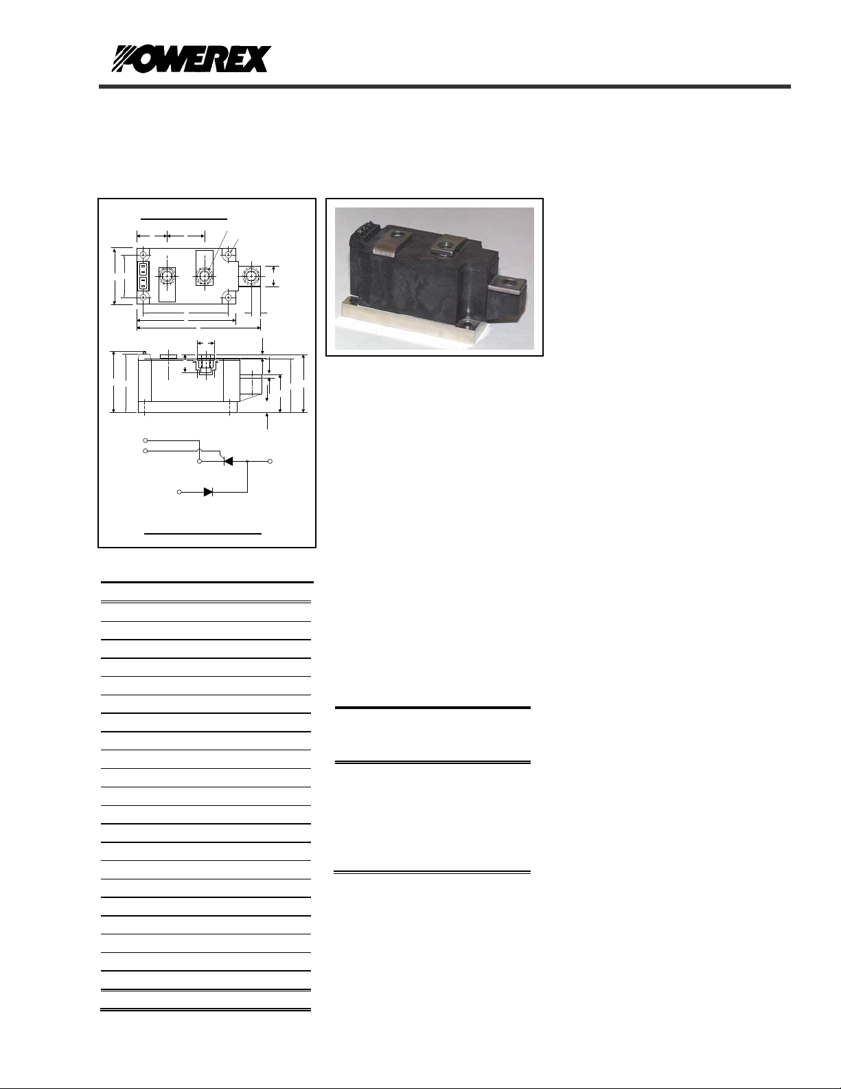
www.pwrx.com Dual SCR/Diode Isolated Module
250 Amperes / Up to 1600 Volts
OUTLINE DRAWING
M K
A
K1
G1
J
G
C
B
V
P
D
E
K1
G1
A
CONNECTION DIAGRAM
ND42 Outline Dimensions
Dimension Inches Millimeters
A 4.57 116
B 3.66 93
C 3.15 80.0
D 2.17 55.1
E 2.06 52.3
F 2.07 52.0
G 1.97 50.0
H 1.90 48.3
J 1.50 38.1
K 1.38 35.0
L 1.26 32.0
M 1.122 28.5
N .71 18.0
P .57 14.5
Q .625 15.9
R .394 10.00
S .350 8.9
T M8 Metric M8
U .250 Dia. 6.35 Dia.
V .110 x .032 2.8 x 0.8
W .12 3.0
Note: Dimensions are for reference only.
T - M8 THD. (3 TYP.)
K
A
Q
SCR 1
K
DIODE 2
U - DIA. (4 TYP.)
AK
S
W
R
N
W
AK
ND42__25
F
H
L
Dual SCR/Diode Isolated
POW-R-BLOK
250 Amperes / 600-1600 Volts
TM
Module
Ordering Information:
Select the complete eight digit
module part number from the table
below.
Example: ND421625 is a 1600Volt,
250 Ampere Dual SCR/Diode
Isolated POW-R-BLOK
TM
Module
Type
ND42 06
Voltage
Volts
(x100)
08
10
12
14
16
Current
Amperes
(x 10)
25
Description:
Powerex Dual SCR/Diode Modules are
designed for use in applications
requiring phase control and isolated
packaging. The modules are isolated
for easy mounting with other
components on a common heatsink.
POW-R-BLOK
recognized by the Underwriters
Laboratories.
Features:
Electrically Isolated Heatsinking
Aluminum Nitride Insulator
Compression Bonded Elements
Metal Baseplate
Low Thermal Impedance
for Improved Current Capability
Quick Connect Gate Terminal
with Provision for Keyed Mating
Plug
UL Recognized
Benefits:
No Additional Insulation
Components Required
Easy Installation
No Clamping Components
Required
Reduce Engineering Time
Applications:
Bridge Circuits
AC & DC Motor Drives
Battery Supplies
Power Supplies
Large IGBT Circuit Front Ends
ND42__25
TM
TM
has been tested and
Revision Date: 05/17/2010
Page 3

A
r
A
Powerex, Inc., 173 Pavilion Lane, Youngwood, Pennsylvania 15697 (724) 925-7272 POW-R-BLOK
ND42__25
TM
www.pwrx.com Dual SCR/Diode Isolated Module
250 Amperes / Up to 1600 Volts
Absolute Maximum Ratings
Characteristics Conditions Symbol Units
Repetitive Peak Forward and Reverse Blocking
Voltage
Non-Repetitive Peak Reverse Blocking Voltage
(t < 5 msec)
RMS Forward Current 180° Conduction, TC=89°C I
verage Forward Current 180° Conduction, TC=89°C I
Peak One Cycle Surge Current, Non-Repetitive 60 Hz, 100% V
Peak Three Cycle Surge Current, Non-Repetitive 60 Hz, 100%V
Peak Ten Cycle Surge Current, Non-Repetitive 60 Hz, 100% V
I2t for Fusing for One Cycle, 8.3 milliseconds I2t 322,000 A2 sec
Maximum Rate-of-Rise of On-State Current,
(Non-Repetitive)
V
D
T
=25°C, IG=500mA,
j
=0.67 V
T
Peak Gate Power Dissipation PGM 16 W
verage Gate Power Dissipation P
Peak Forward Gate Current I
Peak Forward Gate Voltage V
Peak Reverse Gate Voltage V
Operating Temperature TJ -40 to +130 °C
Storage Temperature T
Max. Mounting Torque, M6 Mounting Screw 45
Max. Mounting Torque, M8 Terminal Screw 110
Module Weight, Typical 840 g
1.85 lb
V Isolation @ 25C V
V
V
& V
DRM
RRM
1600 V
RSM
T(RMS)
250 A
8800 A
TSM/IFSM
4685 A
TSM/IFSM
4040 A
TSM/IFSM
reapplied I
RRM
reapplied I
RRM
reapplied I
RRM
T(AV) /IF(AV)
di/dt 800 A/µs
DRM (Rated), ITM
=π I
T(AV)
,
< 0.5µs, tp > 6µs
3 W
G(AV)
4 A
GFM
10 V
GFM
5 V
GRM
-40 to +150 °C
stg
2500 V
rms
up to 1600 V
393
in.-Lb.
5
Nm
in.-Lb.
12
Nm
Revision Date: 05/17/2010
A
Page 4

Powerex, Inc., 173 Pavilion Lane, Youngwood, Pennsylvania 15697 (724) 925-7272 POW-R-BLOK
ND42__25
TM
www.pwrx.com Dual SCR/Diode Isolated Module
250 Amperes / Up to 1600 Volts
Electrical Characteristics, TJ=25°C unless otherwise specified
Characteristics Symbol Test Conditions Min. Max.
Repetitive Peak Forward Leakage Current I
Repetitive Peak Reverse Leakage Current I
Peak On-State Voltage V
Threshold Voltage, Low-level
Slope Resistance, Low-level
Threshold Voltage, High-level
Slope Resistance, High-level
VTM /VFM Coefficients, Full Range
Minimum dV/dt dV/dt Exponential to 2/3 V
Turn-On Time (Typical) ton I
Turn-Off Time (Typical) t
Up to 1600V, TJ=130°C 50 mA
DRM
Up to 1600V, TJ=130°C 50 mA
RRM
I
TM /VFM
V
V
(TO)1
r
T1
(TO)2
r
T2
= 130°C, I = 15%I
T
J
= 130°C, I = πI
T
J
TJ = 130°C, I = 15%I
T
off
V
/VFM = A+ B Ln I +C I + D Sqrt I
TM
T
=130°C, Gate Open
j
= 100A, VD = 100V 7 (Typical) µs
TM
= 130°C, IT= 250A
J
=625A 1.30 V
TM /IFM
to πI
T(AV)
to I
T(AV)
T(AV)
0.819
T(AV)
0.47
TSM
to I
DRM
TSM
A =
B =
C =
D =
500 V/µs
0.5849
0.1060
9.25 E-4
-0.0286
150 (Typical) µs
0.589 V mΩ
0.731 V mΩ
Re-Applied dV/dt = 20V/µs
Linear to 0.8 V
Gate Trigger Current IGT T
Gate Trigger Voltage VGT T
Non-Triggering Gate Voltage V
T
GDM
=25°C, VD=12V 150 mA
j
=25°C, VD=12V 3.0 Volts
j
=130°C, VD= ½ V
j
DRM
0.15 Volts
DRM
Units
Thermal Characteristics
Characteristics Symbol
Thermal Resistance, Junction to Case
Thermal Impedance Coefficients
R
Z
ΘJ-C
ΘJ-C
Per Module, both conducting
Per Junction both conducting
Z
ΘJ-C
+ K
+ K
+ K
Thermal Resistance, Case to Sink Lubricated
R
ΘC-S
= K1 (1-exp(-t/τ1))
(1-exp(-t/τ2))
2
(1-exp(-t/τ3))
3
(1-exp(-t/τ4))
4
Per Module 0.03 °C/W
K
= 5.27E-3
1
K2 = 1.17E-2
K3 = 5.26E-2
K4 = 6.97E-2
τ
= 1.69E-4
1
τ2 = 2.07E-2
τ3 = 2.37E-1
τ4 = 2.46
Max. Units
0.07
0.14
°C/W
°C/W
Revision Date: 05/17/2010
Page 5

Powerex, Inc., 173 Pavilion Lane, Youngwood, Pennsylvania 15697 (724) 925-7272 POW-R-BLOK
ND42__25
TM
www.pwrx.com Dual SCR/Diode Isolated Module
250 Amperes / Up to 1600 Volts
Maximum On-State Forward Voltage Drop
5.00
4.00
3.00
2.00
On-State Voltage - Vtm - Volts
1.00
0.00
10 100 1000 10000
Instantaneous On-State Current - Itm - Amperes
( Tj = 130 °C )
0.14
0.12
0.1
0.08
0.06
0.04
Thermal Impedance - Rjc - °C/W
0.02
0
0.001 0.01 0.1 1 10 100
Maximum Transient Thermal Impedance
(Junction to Case, Per Junction)
Time - t - Seconds
Ma ximum O n -Sta te P ow e r Dis sip ation
300
250
200
150
100
50
Max. Power Dissipation Per SCR - Watts
0
0 50 100 150 200 250 300
(Sinusoidal Waveform)
120°
90°
60°
30°
15°
180
0
CONDUCTION ANGLE
Avera g e On -State C u r re n t - It/If(av) - Am p er es
360
180°
130
125
120
115
110
105
100
95
90
Max. Case Temperature - Tcase -°C
85
80
0 50 100 150 200 250 300
Maximum Allowable Case T emp erature
(Sinusoidal Waveform)
180
360
120°
15°
30°
0
CONDUCTION ANGLE
60°
90°
Average On-State Current - It / If(av) - Am peres
180°
Maximum On-State Power Dissipation
400
350
300
250
200
150
100
50
Max. Power Dissipation Per Junction - Watts
0
0 50 100 150 200 250 300 350 400 450
(Rectangular Waveform)
30°
15°
60°
90°
180°
120°
0
CONDUCTION ANGLE
270°
360°
180
360
130
120
110
100
90
80
Max. Case Temperature - Tcase -°C
70
Average On-State Current - It / If(av) - Amperes
Maximum Allowable Case Temperature
(Rectangular Waveform)
180
270°
360
360°
0
CONDUCTION ANGLE
30°
15°
0 50 100 150 200 250 300 350 400 450
90°
60°
120°
180°
Average On-State Current - It / If(av) - Amperes
Revision Date: 05/17/2010
Page 6

Powerex, Inc., 173 Pavilion Lane, Youngwood, Pennsylvania 15697 (724) 925-7272 POW-R-BLOK
www.pwrx.com Dual SCR/Diode Isolated Module
ND42__25
TM
250 Amperes / Up to 1600 Volts
2000
0.025
1800
0.03
1600
0.04
1400
0.05
1200
0.06
1000
0.08
0.10
800
0.12
0.15
600
Total Power Dissipation (W)
0.20
400
0.30
200
0
10 30 50 70 90 110 130
Powerex ND42--25 Pow-R-Blok 6-Pulse Bridge
0.02 0.015 0.01
Ambient Temperature (C)
Rth S-A (C/W)
Total Power Dissipation vs Maximum Rated Output Current
2000
1800
1600
1400
1200
1000
800
600
400
200
0
0 100 200 300 400 500 600 700 800
Maximum Bridge Output Current (A)
Six-Pulse Bridge Circuit Total Power Dissipation & Maximum Rated Output Current With Sink to Ambient
Resistance of Heatsink as a Parameter.
2000
1800
1600
1400
1200
1000
800
600
400
200
0
Total Power Dissipation (W)
Revision Date: 05/17/2010
 Loading...