

Page 1

6121 Baker Road,
Suite 108
Minnetonka, MN 55345
www.chtechnology.com
Phone (952) 933-6190
Fax (952) 933-6223
1-800-274-4284
Thank you for downloading this document from C&H Technology, Inc.
Please contact the C&H Technology team for the following questions -
Technical
Application
Assembly
Availability
Pricing
Phone – 1-800-274-4284
E-Mail – sales@chtechnology.com
www.chtechnology.com - SPECIALISTS IN POWER ELECTRONIC COMPONENTS AND ASSEMBLIES - www.chtechnology.com
Page 2
®
CONNECTION DIAGRAM
CONNECTION DIAGRAM
M
K
Powerex, Inc., 173 Pavilion Lane, Youngwood, Pennsylvania 15697 (724) 925-7272 POW-R-BLOK
www.pwrx.com Single Diode Isolated Module
600 Amperes / Up to 2600 Volts
E
Ordering Information:
Select the complete eight-digit
module part number from the table
below.
Example: LS412660 is a 2600V,
600 Ampere Single Diode Isolated
POW-R-BLOK
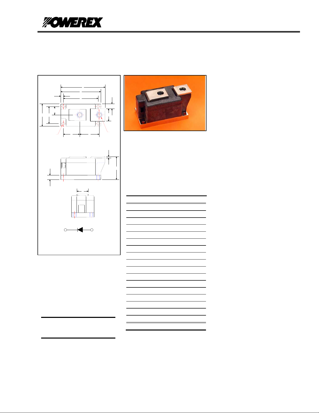
OUTLINE DRAWING
T
G
H
B
"Q"
F
K
CONNECTION DIAGRA
D
A
M N
KA
R
TM
Module.
Type
LS41 08
Voltage
Volts
(x100)
10
12 Thru 26
A
Current
Amperes
(x10)
60
J
"P"
L
LS41__60
Single Diode
POW-R-BLOKTM Module
600 Amperes / 800-2600 Volts
C
LS41 Outline Dimensions
Dimension Inches Millimeters
A 3.15 80.0
B 1.50 38.0
C 2.05 52.1
D 3.62 92.0
E 1.97 50.0
F 0.39 9.9
G 0.24 6.1
H 0.75 19.0
J 0.99 25.1
K 0.48 12.2
L 0.12 3.1
M 1.45 36.8
N 1.76 44.7
P M10 Metric M10
Q 0.250 Dia. 6.35 Dia.
R 0.99 25.1
T 3.99 101.3
Note: Dimensions are for reference only.
LS41__60
Description:
Powerex Single Diode Modules are
designed for use in applications
requiring rectification and isolated
packaging. The modules are isolated
for easy mounting with other
components on a common heatsink.
POW-R-BLOK
recognized by the Underwriters
Laboratories.
Features:
Electrically Isolated Heatsinking
Aluminum Nitride Isolator
Compression Bonded Elements
Metal Baseplate
Low Thermal Impedance
for Improved Current Capability
UL Recognized
Benefits:
No Additional Insulation
Components Required
Easy Installation
No Clamping Components
Required
Reduce Engineering Time
Applications:
Bridge Circuits
AC & DC Motor Drives
Battery Supplies
Power Supplies
Large IGBT Circuit Front Ends
TM
TM
has been tested and
Revision Date: 09/08/2010
Page 3

®
A
Powerex, Inc., 173 Pavilion Lane, Youngwood, Pennsylvania 15697 (724) 925-7272 POW-R-BLOK
www.pwrx.com Single Diode Isolated Module
600 Amperes / Up to 2600 Volts
LS41__60
TM
Absolute Maximum Ratings
Characteristics Conditions Symbol Units
Repetitive Peak Reverse Blocking Voltage V
Non-Repetitive Peak Reverse Blocking Voltage
V
(t < 5 msec)
RMS Forward Current I
verage Forward Current 180° Conduction, TC=106°C I
Peak One Cycle Surge Current, Non-Repetitive
Peak Three Cycle Surge Current, Non-Repetitive
Peak Ten Cycle Surge Current, Non-Repetitive
60 Hz, V
50 Hz, V
60 Hz, V
50 Hz, V
60 Hz, V
50 Hz, V
60 Hz, V
50 Hz, V
60 Hz, V
50 Hz, V
60 Hz, V
50 Hz, V
60 Hz, V
50 Hz, V
60 Hz, V
50 Hz, V
=V
, Tj=150C
RRM
r
=V
, Tj=150C
RRM
r
=V
, Tj=25C
RRM
r
=V
, Tj=25C
RRM
r
=0 Tj=150C
r
=0, Tj=150C
r
=0, Tj=25C
r
=0, Tj=25C
r
=0 Tj=150C
r
=0, Tj=150C
r
=0, Tj=25C
r
=0, Tj=25C
r
=0 Tj=150C
r
=0, Tj=150C
r
=0, Tj=25C
r
=0, Tj=25C
r
I2t for Fusing for One Cycle 8.3 milliseconds, Tj=150C
8.3 milliseconds, Tj=25C
10 milliseconds, Tj=150C
10 milliseconds, Tj=25C
Operating Temperature TJ -40 to +150 °C
Storage Temperature T
Max. Mounting Torque, M6 Mounting Screw 55
Max. Mounting Torque, M10 Terminal Screw 110
Module Weight, Typical 816 g
1.80 lb
V Isolation @ 25C
up to 2600 V
RRM
V
RSM
950 A
F(RMS)
600 A
F(AV)
I
FSM
I
FSM
I
FSM
I
FSM
I
FSM
I
FSM
I
FSM
I
FSM
I
FSM
I
FSM
I
FSM
I
FSM
I
FSM
I
FSM
I
FSM
I
FSM
2
I
t
2
I
t
2
I
t
2
I
t
-40 to +150 °C
stg
+ 100 V
RRM
21,000
19,000
24,360
22,040
31,500
28,500
36,540
33,060
25,285
22,875
29,330
26,535
19,865
17,975
23,045
20,850
4,100,000
5,500,000
4,000,000
5,400,000
A
A
A
A
A
A
A
A
A
A
A
A
A
A
A
A
2
A
sec
2
A
sec
2
A
sec
2
A
sec
in. – Lb.
6
Nm
in. – Lb.
12
V
rms
3000 V
Nm
Revision Date: 09/08/2010
Page 4

®
Powerex, Inc., 173 Pavilion Lane, Youngwood, Pennsylvania 15697 (724) 925-7272 POW-R-BLOK
www.pwrx.com Single Diode Isolated Module
600 Amperes / Up to 2600 Volts
LS41__60
TM
Electrical Characteristics, TJ=25°C unless otherwise specified
Characteristics Symbol Test Conditions Min. Max.
Repetitive Peak Reverse Leakage Current I
Peak On-State Voltage VFM
Threshold Voltage, Low-level
Slope Resistance, Low-level
Threshold Voltage, High-level
Slope Resistance, High-level
VTM Coefficients, Full Range
Up to 2600V, TJ=150°C 40 mA
RRM
1.19 V
0.243 V mΩ
0.145 V mΩ
A =
B =
C =
D =
5.05E-01
3.44E-02
8.13E-05
6.57E-03
V
V
(TO)1
r
T1
(TO)2
r
T2
T
=150°C, IFM=1800A
J
= 150°C, I = 15%I
T
J
F(AV)
to πI
0.747
F(AV)
= 150°C, I = πI
T
J
F(AV)
to I
0.914
FSM
TJ = 150°C, I = 15%I
F(AV)
to I
FSM
V
= A + B Ln I +C I + D Sqrt I
TM
Units
Thermal Characteristics
Characteristics Symbol
Thermal Resistance, Junction to Case
Thermal Impedance Coefficients
R
ΘJ-C
Z
Z
ΘJ-C
Per Module / Junction 0.0650 °C/W
ΘJ-C
+ K
+ K
+ K
Thermal Resistance, Case to Sink Lubricated
R
ΘC-S
= K1 (1-exp(-t/τ1))
(1-exp(-t/τ2))
2
(1-exp(-t/τ3))
3
(1-exp(-t/τ4))
4
Per Module 0.02 °C/W
Information presented is based upon manufacturers testing and projected capabilities.
This information is subject to change without notice.
The manufacturer makes no claim as to the suitability of use, reliability, capability,
or future availability of this product.
K
= 8.03E-04
1
K2 = 1.03E-02
K3 = 1.64E-02
K4 = 3.75E-02
Max. Units
τ
= 3.39E-04
1
τ2 = 3.15E-03
τ3 = 1.06E-01
= 2.066
τ
4
Revision Date: 09/08/2010
Page 5

®
Powerex, Inc., 173 Pavilion Lane, Youngwood, Pennsylvania 15697 (724) 925-7272 POW-R-BLOK
www.pwrx.com Single Diode Isolated Module
600 Amperes / Up to 2600 Volts
5.00
4.00
3.00
2.00
On-State Voltage - Vfm - Volts
1.00
0.00
10 100 1000 10000 100000
Maximum On-State Forward Voltage Drop
( Tj = 150 °C )
Instantaneous On-State Current - Ifm - Amperes
Maximum Transient Thermal Impedance
0.07
0.06
0.05
0.04
0.03
0.02
Thermal Impedance - Zjc - °C/W
0.01
0
0.001 0.01 0.1 1 10 100
LS41__60
(Junction to Case)
TM
Time - t - Seconds
Maximum On-State Power Dissipation
700
600
500
400
300
200
Max. Power Dissipation - W atts
100
0
0 100 200 300 400 500 600 700
1000
900
800
700
600
500
400
300
Max. Power Dissipation - Watts
200
100
0
0 200 400 600 800 1000
(Sinusoidal Waveform)
90°
60°
30°
15°
180
0
CONDUCTION ANGLE
Average On-State Current - If(av) - Amperes
Maximum On-State Power Dissipation
(Rectangular Waveform)
270°
180°
120°
90°
60°
30°
15°
0
CONDUCTION ANGLE
Average On-State Current - If(av) - Amperes
120°
180
180°
360
360°
360
150
145
140
135
130
125
120
115
110
Max. Case Temperature - Tcase -°C
105
100
0 100 200 300 400 500 600 700
150
140
130
120
110
100
Max. Case Temperature - Tcase -°C
90
80
0 200 400 600 800 1000
Maximum Allowable Case Temperature
(Sinusoidal Waveform)
180
0
15°
30°
CONDUCTION ANGLE
60°
90°
120°
Average On-State Current - If(av) - Amperes
Maximum Allowable Case Temperature
(Rectangular Waveform)
0
120°
180°
CONDUCTION ANGLE
270°
15°
30°
60°
90°
Average On-State Current - If(av) - Amperes
360
180°
180
360
360°
Revision Date: 09/08/2010
 Loading...