

Page 1
6121 Baker Road,
Suite 108
Minnetonka, MN 55345
www.chtechnology.com
Phone (952) 933-6190
Fax (952) 933-6223
1-800-274-4284
Thank you for downloading this document from C&H Technology, Inc.
Please contact the C&H Technology team for the following questions -
Technical ● Application ● Assembly ● Availability ● Pricing
Phone – 1-800-274-4284
E-Mail – sales@chtechnology.com
www.chtechnology.com - SPECIALISTS IN POWER ELECTRONIC COMPONENTS AND ASSEMBLIES
-
www.chtechnology.com
Page 2
www.vishay.com
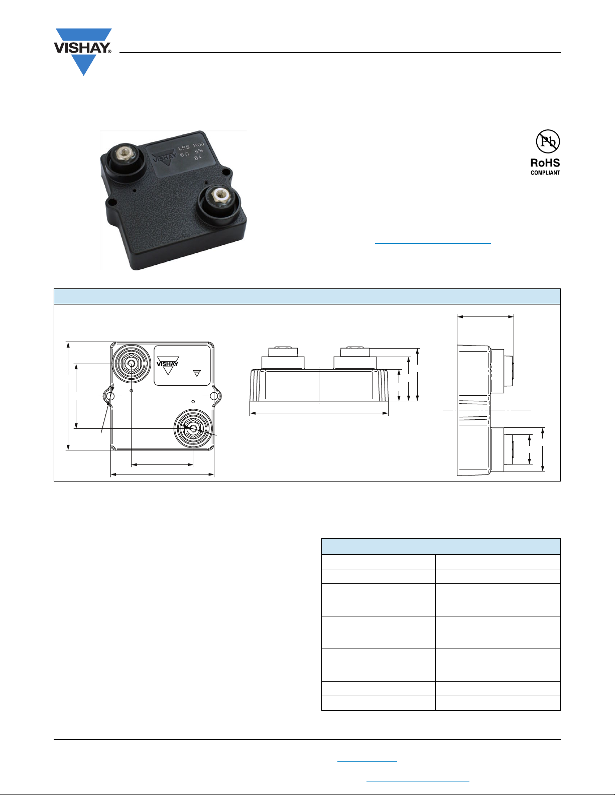
2 x M4 useful depth: 8
57
34
60
36
2 x Ø 4.2
LPS 1100
I5U 5 %
V2
64.7
15.2
21.2
25.2
13.6
Ø 20
25.8 ± 1
Power Resistor for Mounting onto a Heatsink
DIMENSIONS in millimeters
Thick Film Technology
FEATURES
• LPS high power: 1100 W
• Wide resistance range: 1 to 1.3 k
E24 series
•Non inductive
• Easy mounting
• Low thermal radiation of the case
• Material categorization: For definitions of compliance
please see www.vishay.com/doc?99912
LPS 1100
Vishay Sfernice
Notes
• Tolerances unless stated: ± 0.2 mm
• Power dissipation is 1100 W by using a water cooled heatsink at T
onto heatsink) and R
contact estimated at 0.07 °C/W.
th
MECHANICAL SPECIFICATIONS
Mechanical Protection Insulated case and resin for
potting UL 94 V-0
Resistive Element Thick film
End Connections Screws M4
Tightening Torque Connections 2 Nm
Tightening Torque Heatsink 2 Nm
Maximum Torque 2.5 Nm
Weight 79 g ± 10 %
ENVIRONMENTAL SPECIFICATIONS
Temperature Range - 55 °C to + 200 °C
Climatic Category 55/200/56
Revision: 14-Jun-12
THIS DOCUMENT IS SUBJECT TO CHANGE WITHOUT NOTICE. THE PRODUCTS DESCRIBED HEREIN AND THIS DOCUMENT
ARE SUBJECT TO SPECIFIC DISCLAIMERS, SET FORTH AT www.vishay.com/doc?91000
For technical questions, contact: sfer@vishay.com
= 15 °C of Rth = 0.059 °C/W (25 °C to the nearest point of the resistor
water
ELECTRICAL SPECIFICATIONS
Resistance Range 1 to 1.3 k
Tolerances ± 1 % to ± 10 %
Power Rating and
Thermal Resistance
Temperature Coefficient
(- 55 °C to + 200 °C),
IEC 60115-1
Dielectric Strength
IEC 60115-1,
1 min, 10 mA max.
Insulation 104 M
Inductance 0.1 μH
1
1100 W at + 25 °C
On heatsink
R
: 0.039 °C/W
th(j-c)
± 150 ppm/°C
7 kV
RMS
Document Number: 50059
or 12 kV
RMS
Page 3
P
T
R
th (j - c)
R
th (c - h)
R
th (h - a)
++
---------------------------------------------------------------------------------------------
=
T 200 °C - 18 °C 182 °C=
R
th (j - c)RTH (c - h)RTH (h - a)
+
T
P
-------
182
850
----------
0.214 °C/W== =+
R
th (j - c)
0.039 °C/W=
R
th (c - h)Rth (h - a)
0.214 °C/W - 0.039 °C/W 0.175 °C/W==+
LPS 1100
www.vishay.com
PERFORMANCE
TESTS CONDITIONS REQUIREMENTS
IEC 60115-1: 2 x Pr/10 s for heatsink with
0.26 °C/W (maximum power: 700 W)
R
Momentary Overload
Rapid Temperature Change
Load Life
Humidity (Steady State) AEC-Q200 conditions: IEC 60115-1, 1000 h RH 85 %/85 °C ± (0.5 % + 0.05 )
Mechanical Shock
Vibration
Climatic Sequence AEC-Q200 conditions: IEC 60115-1 (55/200/56) ± (1 % + 0.05 )
1.6 x Pr/1 s for heatsink with 0.26 °C/W >R
AEC-Q200 conditions: IEC 60115-1/IEC 60068-2-14, Test Na
AEC-Q200 conditions: MIL-STD-202 method 213 condition D
AEC-Q200 conditions: MIL-STD-202 method 204 condition D
th(h-a)
(maximum power: 1800 W)
50 cycles (- 55 °C to + 200 °C) ± (0.5 % + 0.05 ) for all the ohmic values
1000 cycles (- 55 °C to + 200 °C)
AEC-Q200 conditions: IEC 60115-1
1000 h (90/30) Pr
(100 g’s/6 ms 3.75 m/s)
(5 g, 20 min 10/2000 Hz)
0.059 °C/W
th(h-a)
± (5 % + 0.05 ) for R < 38 U
± (0.5 % + 0.05 ) for R 38 U
± (5 % + 0.05 ) for R < 38 U
± (0.5 % + 0.05 ) for R 38 U
RECOMMENDATIONS FOR MOUNTING ONTO A HEATSINK
• Surfaces in contact must be carefully cleaned.
• The heatsink must have an acceptable flatness: From 0.05 mm to 0.1 mm/100 mm.
• Roughness of the heatsink must be around 6.3 μm. In order to improve thermal conductivity, surfaces in contact (ceramic,
heatsink) should be coated with a silicone grease (type SI 340 from Blue Star Silicones). Thermal film (type Q-pad II from
Berquist) is also possible, easier and faster to install than grease but with a lower efficiency for the power dissipation.
• The fastening of the resistor to the heatsink is under pressure control of two screws tightened at 2 Nm for full power
availability.
Tightening Torque on Heatsink
• The following accessories are supplied with each product:
- 2 screws CHC M4 x 25 class 8.8 and 2 M4 contact lock washers for heatsink mounting
- 2 screws TH M4 x 6/6 and 2 M4 contact lock washers for connections. 2 off CHC M4 x 16/16 class 8
LPS 1100
2 Nm
Vishay Sfernice
± (0.25 % + 0.05 )
± (1 % + 0.05 )
± (1 % + 0.05 )
CHOICE OF THE HEATSINK AND THE THERMAL INTERFACE
The user must choose the heatsink according to the working conditions of the component (power, room temperature).
Maximum working temperature must not exceed 200 °C. The dissipated power is simply calculated by the following ratio:
P: Expressed in W
T: Difference between maximum working temperature and room temperature or fluid cooling temperature.
R
: Thermal resistance value measured between resistive layer and outer side of the resistor. It is the thermal
th (j - c)
R
th (c - h)
R
th (h - a)
Example:
th (c - h)
+ R
R
Revision: 14-Jun-12
THIS DOCUMENT IS SUBJECT TO CHANGE WITHOUT NOTICE. THE PRODUCTS DESCRIBED HEREIN AND THIS DOCUMENT
resistance of the component: 0.039 °C/W.
: Thermal resistance value measured between outer side of the resistor and upper side of the heatsink. This is the
thermal resistance of the interface (grease, thermal pad), and the quality of the fastening device.
: Thermal resistance of the heatsink.
for LPS 1100 power dissipation 850 W at + 18 °C fluid temperature.
th (h - a)
ARE SUBJECT TO SPECIFIC DISCLAIMERS, SET FORTH AT www.vishay.com/doc?91000
For technical questions, contact: sfer@vishay.com
2
Document Number: 50059
Page 4
www.vishay.com
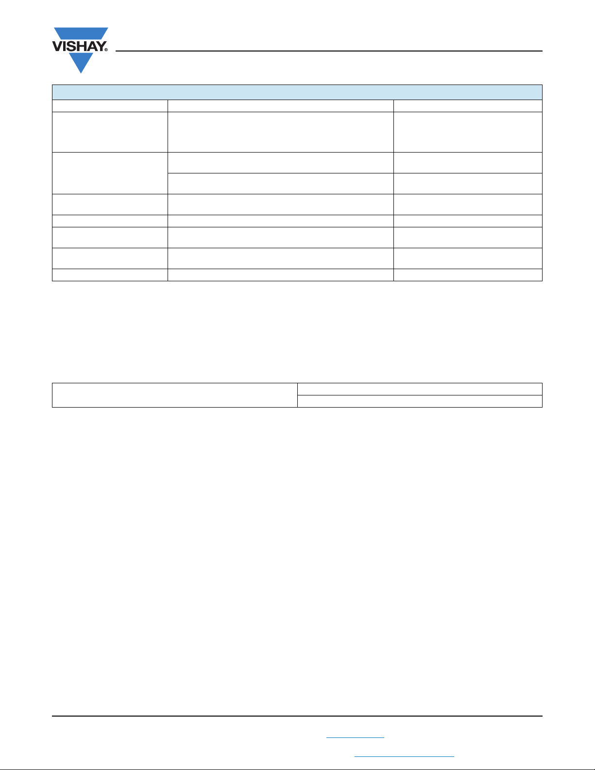
ENERGY IN J
0.01
0.1
1
10
100
10 000
OVERLOAD DURATION IN s
1
10
-7
10-610
-5
10
-4
10
-3
10-210
-1
1000
LPS 1100
Vishay Sfernice
CONFIG. 1:
WATER COOLING
HEATSINK CP15 AND
THERMAL GREASE SI340
CONFIG. 2:
AIR COOLING
HEATSINK P207/250 AND
THERMAL GREASE SI340
CONFIG. 3:
WATER COOLING
HEATSINK CP15 AND
THERMAL PAD Q-PAD II
CONFIG. 4:
AIR COOLING
HEATSINK P207/250 AND
THERMAL PAD Q-PAD II
Power Dissipation (W) 1100 350 650 285
T° Resistive Element (°C) 200 200 200 200
R
max. (°C/W) 0.039 0.039 0.039 0.039
th(j-c)
R
typ. (°C/W) 0.070 0.201 0.187 0.315
th(c-h)
R
max. (°C/W) 0.059 0.260 0.059 0.260
th(h-a)
Fluid T° (°C) 15 (water) 25 (air) 15 (water) 25 (air)
Note
• Configuration 1: Water cooling heatsink (CP15 from Lytron (304 mm x 95.3 mm x 8 mm) with water flow rate 4LPM and thermal grease Si340
from BlueStar Silicones
Configuration 2: Air cooling heatsink P207/250 from Semikron (250 mm x 200 mm x 72 mm) and thermal grease Si340 from BlueStar
Silicones
Configuration 3: Water cooling heatsink (CP15 from Lytron (304 mm x 95.3 mm x 8 mm) with water flow rate 4LPM and thermal pad
Q-pad II from Berquist
Configuration 4: Air cooling heatsink P207/250 from Semikron (250 mm x 200 mm x 72 mm) and thermal pad Q-pad II from Berquist
OVERLOAD
In any case the applied voltage must be lower than
= 6600 V.
U
I
Short time overload: 2 x Pr/10 s for heatsink with
R
0.26 °C/W (maximum power: 700 W) and 1.6 x
th(h-a)
Pr/1 s for heatsink with 0.26 °C/W > R
(maximum power: 1800 W).
Accidental overload: The values indicated on the following
0.059 °C/W
th(h-a)
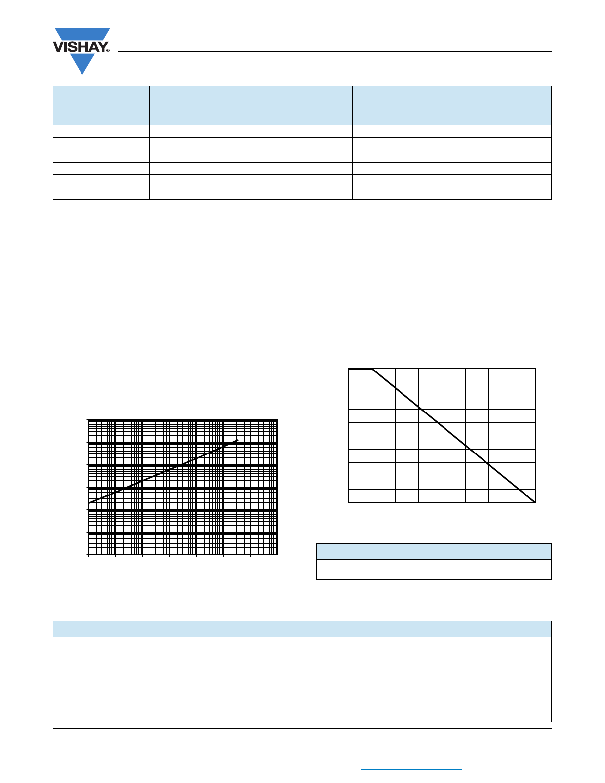
POWER RATING
The temperature of the case should be maintained within
the limit specified in the following figure. To optimize
the thermal conduction, contacting surfaces should be
coated with silicone grease or thermal film, and heatsink
mounting screws tightened to 2 Nm.
100
graph are applicable to resistors in air or mounted onto a
heatsink.
80
ENERGY CURVE
60
40
RATED POWER IN %
20
0
HEATSINK TEMPERATURE IN °C
PACKAGING
Box of 15 units
MARKING
Series, style, ohmic value (in ), tolerance (in %),
manufacturing date, Vishay Sfernice trademark.
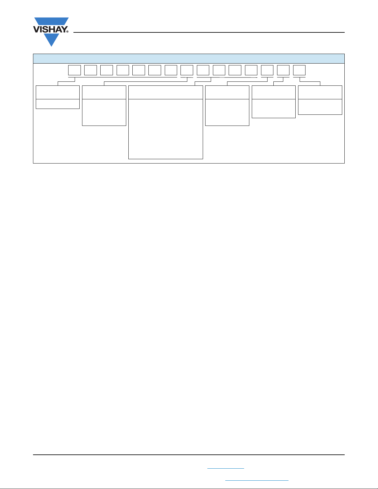
ORDERING INFORMATION
LPS 1100 1 k ± 1 % xxx BO15 e
MODEL STYLE
RESISTANCE
VALUE
TOLERANCE
± 1 %
± 2 %
± 5 %
± 10 %
Revision: 14-Jun-12
3
For technical questions, contact: sfer@vishay.com
THIS DOCUMENT IS SUBJECT TO CHANGE WITHOUT NOTICE. THE PRODUCTS DESCRIBED HEREIN AND THIS DOCUMENT
ARE SUBJECT TO SPECIFIC DISCLAIMERS, SET FORTH AT www.vishay.com/doc?91000
CUSTOM
DESIGN
Optional on
request:
special TCR,
shape, etc.
PACKAGING LEAD (Pb)-FREE
Document Number: 50059
2000175150125100755025
Page 5
www.vishay.com
GLOBAL PART NUMBER INFORMATION
LPS 1100
Vishay Sfernice
J BS11 00H4 RL P 70
GLOBAL
MODEL
LPS 1100
DIELECTRIC OHMIC VALUE TOLERANCE PACKAGING SPECIAL
L = Dielectric
strengh 7 kV
H = Dielectric
strengh 12 kV
The first three digits are
significant figures and the
last digit specifies the
number of zeros to follow.
R designates decimal point.
48R7 = 48.7
47R0 = 47
1001 = 1 k
4R70 = 4.7
R240 = 0.24
F = 1 %
G = 2 %
J = 5 %
K = 10 %
B = Box 15 pieces
N = Box 15 pieces
n/a
As applicable
ZAx
Revision: 14-Jun-12
For technical questions, contact: sfer@vishay.com
THIS DOCUMENT IS SUBJECT TO CHANGE WITHOUT NOTICE. THE PRODUCTS DESCRIBED HEREIN AND THIS DOCUMENT
ARE SUBJECT TO SPECIFIC DISCLAIMERS, SET FORTH AT www.vishay.com/doc?91000
4
Document Number: 50059
Page 6

Legal Disclaimer Notice
www.vishay.com
Vishay
Disclaimer
ALL PRODUCT, PRODUCT SPECIFICATIONS AND DATA ARE SUBJECT TO CHANGE WITHOUT NOTICE TO IMPROVE
RELIABILITY, FUNCTION OR DESIGN OR OTHERWISE.
Vishay Intertechnology, Inc., its affiliates, agents, and employees, and all persons acting on its or their behalf (collectively,
“Vishay”), disclaim any and all liability for any errors, inaccuracies or incompleteness contained in any datasheet or in any other
disclosure relating to any product.
Vishay makes no warranty, representation or guarantee regarding the suitability of the products for any particular purpose or
the continuing production of any product. To the maximum extent permitted by applicable law, Vishay disclaims (i) any and all
liability arising out of the application or use of any product, (ii) any and all liability, including without limitation special,
consequential or incidental damages, and (iii) any and all implied warranties, including warranties of fitness for particular
purpose, non-infringement and merchantability.
Statements regarding the suitability of products for certain types of applications are based on Vishay’s knowledge of typical
requirements that are often placed on Vishay products in generic applications. Such statements are not binding statements
about the suitability of products for a particular application. It is the customer’s responsibility to validate that a particular
product with the properties described in the product specification is suitable for use in a particular application. Parameters
provided in datasheets and/or specifications may vary in different applications and performance may vary over time. All
operating parameters, including typical parameters, must be validated for each customer application by the customer’s
technical experts. Product specifications do not expand or otherwise modify Vishay’s terms and conditions of purchase,
including but not limited to the warranty expressed therein.
Except as expressly indicated in writing, Vishay products are not designed for use in medical, life-saving, or life-sustaining
applications or for any other application in which the failure of the Vishay product could result in personal injury or death.
Customers using or selling Vishay products not expressly indicated for use in such applications do so at their own risk and agree
to fully indemnify and hold Vishay and its distributors harmless from and against any and all claims, liabilities, expenses and
damages arising or resulting in connection with such use or sale, including attorneys fees, even if such claim alleges that Vishay
or its distributor was negligent regarding the design or manufacture of the part. Please contact authorized Vishay personnel to
obtain written terms and conditions regarding products designed for such applications.
No license, express or implied, by estoppel or otherwise, to any intellectual property rights is granted by this document or by
any conduct of Vishay. Product names and markings noted herein may be trademarks of their respective owners.
Material Category Policy
Vishay Intertechnology, Inc. hereby certifies that all its products that are identified as RoHS-Compliant fulfill the
definitions and restrictions defined under Directive 2011/65/EU of The European Parliament and of the Council
of June 8, 2011 on the restriction of the use of certain hazardous substances in electrical and electronic equipment
(EEE) - recast, unless otherwise specified as non-compliant.
Please note that some Vishay documentation may still make reference to RoHS Directive 2002/95/EC. We confirm that
all the products identified as being compliant to Directive 2002/95/EC conform to Directive 2011/65/EU.
Revision: 12-Mar-12
1
Document Number: 91000
 Loading...