

Page 1
Aluminum Capacitors
Power Printed Wiring Style
FEATURES
• Polarized aluminum electrolytic capacitors,
non-solid electrolyte
• Large types, cylindrical aluminum case,
insulated
• Provided with keyed polarity
• Very long useful life: 15 000 h at 85 °C
• Low ESR, high ripple current capability
• High resistance to shock and vibration
EYV
Vishay Roederstein
RoHS
COMPLIANT
N
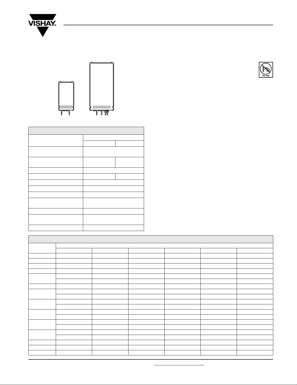
Component outlines
QUICK REFERENCE DATA
DESCRIPTION
Nominal case size
(Ø D x L in mm)
Rated capacitance range
(E6 series), C
Tolerance on C
Rated voltage range, U
Category temperature range - 40 °C to + 85 °C
Endurance test at 85 °C 5000 h
Useful life at 85 °C 15 000 h
Useful life at 40 °C,
1.4 x I
Shelf life at 0 V, 85 °C 500 h
Based on sectional
specification
Climatic category IEC 60068 40/085/56
SELECTION CHART FOR CR, UR AND RELEVANT NOMINAL CASE SIZES (Ø D x L in mm)
C
(µF)
1000 - - - - 25 x 30 30 x 40
1500 - - - 25 x 30 25 x 40 35 x 40
2200
3300 - 25 x 30 25 x 40 30 x 40 35 x 40 40 x 50
4700
6800
10 000
NO
15 000
22 000
33 000 40 x 50 40 x 70 40 x 100 - - 47 000 40 x 70 40 x 100 - - - 68 000 40 x 100 - - - - -
Document Number: 25126 For technical questions, contact: aluminumcaps2@vishay.com
Revision: 21-Aug-08 1
R
R
R
applied
R
R
470-----25x30
680 - - - - - 25 x 40
10 16 25 40 63 100
T
25 x 30 25 x 40 30 x 40 35 x 40 35 x 50 40 x 70
25 x 40 30 x 40 35 x 40 35 x 50 40 x 50 40 x 100
30 x 40 35 x 40 35 x 50 40 x 50 40 x 70 -
35 x 40 35 x 50 40 x 50 40 x 70 40 x 100 -
35 x 50 40 x 50 40 x 70 40 x 100 - 40x40-----
≤ 100 V > 100 V
to 68 000 µF
10 V to 100 V 250 V to 400 V
FOR
- - 25 x 30 25 x 40 30 x 40 35 x 50
-----40x40
----40x40-
---40x40--
--40x40---
-40x40----
VALU E
25 x 30 to 40 x 100
470 µF
- 10 % to + 30 %
200 000 h
IEC 60384-4/EN130300
47 µF
to 1000 µF
NE
APPLICATIONS
• Computer, telecommunication and industrial systems
• Smoothing and filtering
• Standard and switched mode power supplies
• Energy storage in pulse systems
MARKING
The capacitors are marked (where possible) with the
following information:
• Rated capacitance (in µF)
• Tolerance on rated capacitance, code letter in accordance
with IEC 60062 (Q for - 10/+ 30 %)
W DE
• Rated voltage (in V)
• Date code (YYMM)
• Name of manufacturer
• Code for factory of origin
• Polarity of the terminals and ‘-’ sign to indicate the negative
terminal, visible from the top and/or side of the capacitor
• Code number
• Climatic category in accordance with IEC 60068
U
(V)
R
SIG
www.vishay.com
Page 2
EYV
Vishay Roederstein
SELECTION CHART FOR CR, UR AND RELEVANT NOMINAL CASE SIZES (Ø D x L in mm)
C
R
(µF)
47 - 25 x 30 25 x 30
68 - 25 x 40 25 x 40
100 25 x 30 30 x 40 30 x 40
150 25 x 40 35 x 40 35 x 40
220
330 35 x 40 40 x 50 40 x 50
470
680 40 x 50 - 40 x 100
1000 40 x 70 - -
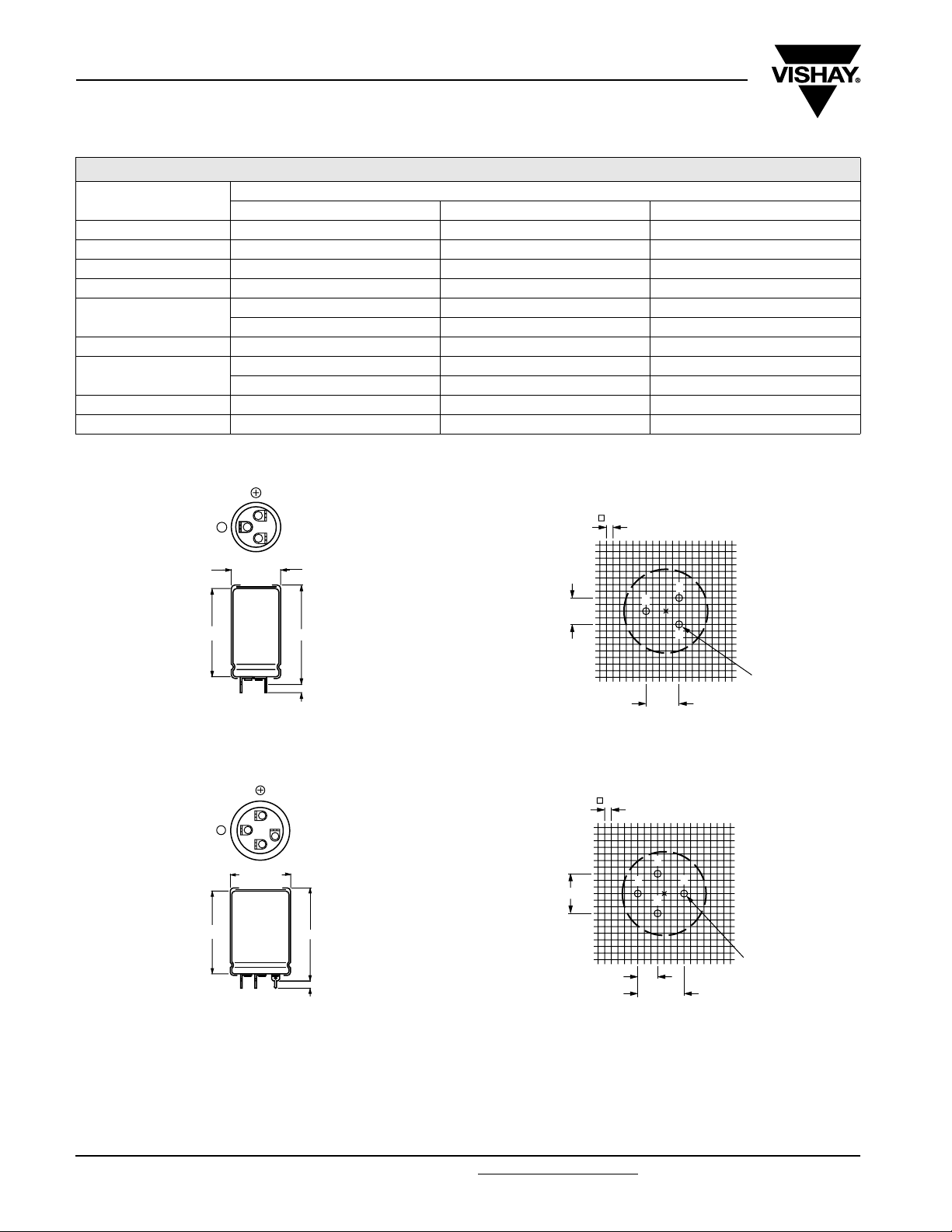
DIMENSIONS in millimeters AND AVAILABLE FORMS
1
5
-
2
250 385 400
30 x 40 35 x 50 35 x 50
35 x 50 40 x 70 40 x 70
40 x 40 - -
Aluminum Capacitors
Power Printed Wiring Style
U
(V)
R
- 40 x 40 40 x 40
SIG
2.5
N
L
1 = Positive terminal
5 = Negative terminal
Case Ø D = 25 mm
Fig.1 Printed wiring pin version
T
L
1 = Positive terminal
5 = Negative terminal
Case Ø D = 30 mm and 35 mm
NO
Fig.3 Printed wiring pin version Fig.4 Mounting hole pattern viewed from the component side
-
Ø D
+ 1 max.
L + 5 max.
5.1 ± 0.1
12
5
3
FOR
Ø D
+ 1 max.
L + 5 max.
5.1 ± 0.1
W DE
10 ± 0.1
NE
Case Ø D = 25 mm
Fig.2 Mounting hole pattern viewed from the component side
15 ± 0.1
Case Ø D = 30 mm and 35 mm
2.5
7.5 ± 0.1
2
5
1
1.3
1.3
(4 x)
(3 x)
12.5
± 0.1
2
3
5
1
17.5
± 0.1
www.vishay.com For technical questions, contact: aluminumcaps2@vishay.com Document Number: 25126
2 Revision: 21-Aug-08
Page 3
EYV
Aluminum Capacitors
Power Printed Wiring Style
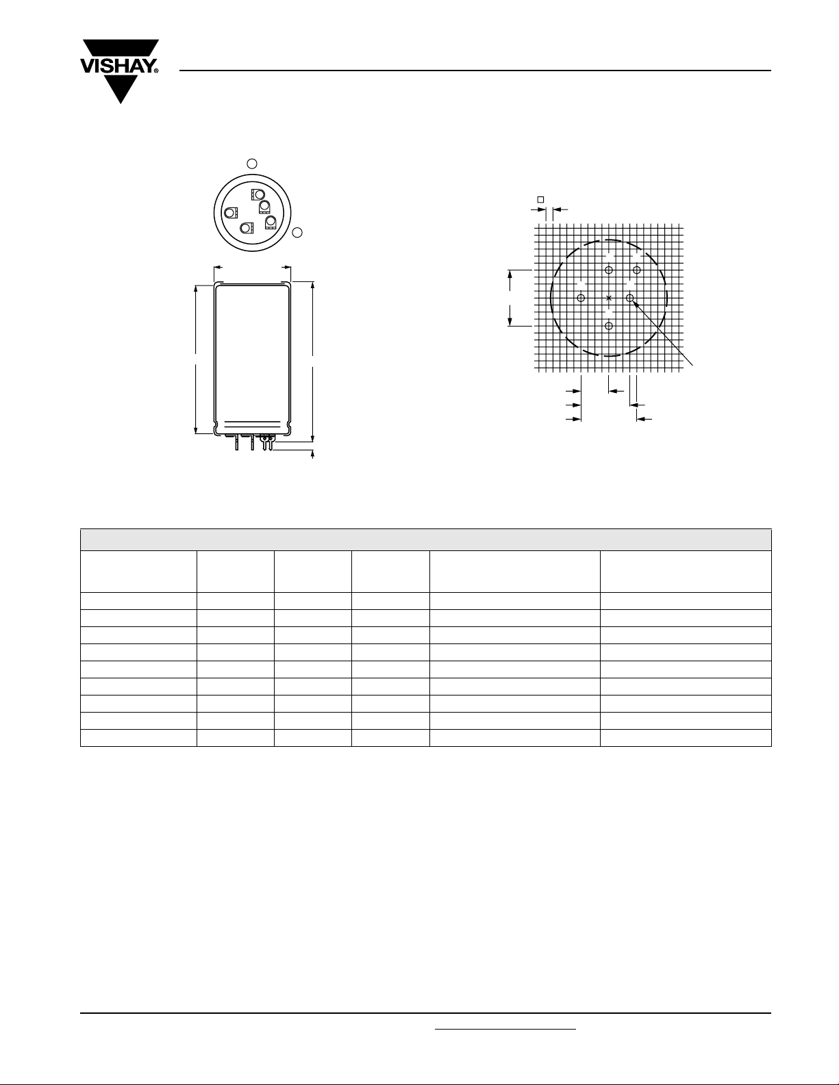
DIMENSIONS in millimeters AND AVAILABLE FORMS
+
1
4
2
Ø D + 1 max.
L
1 = Positive terminal
5 = Negative terminal
Case Ø D = 40 mm
Fig.5 Printed wiring pin version
5
3
-
L + 1 max.
5.1 ± 0.1
Vishay Roederstein
2.5
345
20 ± 0.1
10 ± 0.1
ve terminal
1 = Positi
5 = Negative terminal
Case Ø D = 40 mm
Fig.6 Mounting hole pattern viewed from the component side
2
17.5 ± 0.1
20 ± 0.1
1
SIG
1.3
(5 x)
N
W DE
DIMENSIONS in millimeters, MASS AND PACKAGING QUANTITIES
NOMINAL
CASE SIZE
Ø D x L
25 x 30 26 35 ≈ 24 100 290 x 280 x 50
25 x 40 26 45 ≈ 28 100 290 x 280 x 60
30 x 40 31 45 ≈ 38 100 340 x 330 x 60
35 x 40 36 45 ≈ 51 50 390 x 198 x 60
35 x 50 36 55 ≈ 66 50 390 x 198 x 70
40 x 40 41 45 ≈ 78 50 440 x 223 x 60
40 x 50 41 55 ≈ 82 50 440 x 223 x 70
40 x 70 41 75 ≈ 110 25 230 x 230 x 90
40 x 100 41 105 ≈ 176 25 230 x 230 x 120
Ø D
max.
L
max.
MASS
(g)
PACKAGING QUANTITIES
(units per box)
NE
CARDBOARD
BOX DIMENSIONS
L x W x H
FOR
MOUNTING
When a number of capacitors are connected in a bank, they must not be closer together than 15 mm, when no derating of ripple
current and/or temperature is applied.
Pin numbers 2, 3 and 4 (if present) must be free from the electrical circuit.
T
NO
Document Number: 25126 For technical questions, contact: aluminumcaps2@vishay.com
Revision: 21-Aug-08 3
www.vishay.com
Page 4

EYV
Vishay Roederstein
Aluminum Capacitors
Power Printed Wiring Style
ELECTRICAL DATA
SYMBOL DESCRIPTION
C
R
I
R
I
L1
I
L5
ESR max. equivalent series resistance at 100 Hz
Z max. impedance at 10 kHz
Note
(1)
Unless otherwise specified, all electrical values apply at
Ta= 20 °C, P = 86 kPa to 106 kPa, RH = 45 % to 75 %
ELECTRICAL DATA AND ORDERING INFORMATION
U
R
(V)
10
16
25
40
NO
63
rated capacitance at 100 Hz
rated RMS ripple current at 100 Hz,
85 °C or at 20 kHz, 70 °C
max. leakage current after 1 minute at U
max. leakage current after 5 minutes at U
C
R
100 Hz
(µF)
4700 25 x 30 2.4 4.6 0.28 0.10 74 50 MALPEYV00AV447C02W
6800 25 x 40 3.2 6.1 0.41 0.14 51 37 MALPEYV00AB468C02W
10 000 30 x 40 3.8 7.2 0.60 0.20 39 29 MALPEYV00BB510C02W
15 000 35 x 40 4.1 7.8 0.90 0.30 35 26 MALPEYV00CB515C02W
22 000 35 x 50 5.0 9.5 1.32 0.44 27 21 MALPEYV00CD522C02W
22 000 40 x 40 4.2 8.0 1.32 0.44 36 27 MALPEYV00DB522C02W
33 000 40 x 50 5.0 9.5 1.98 0.66 29 22 MALPEYV00DD533C02W
47 000 40 x 70 6.8 12.9 2.82 0.94 20 17 MALPEYV00DG547C02W
68 000 40 x 100 9.2 17.5 4.08 1.36 15 14 MALPEYV00DM568C02W
3300 25 x 30 2.4 4.6 0.32 0.11 75 50 MALPEYV00AV433D02W
4700 25 x 40 3.1 5.9 0.45 0.15 52 37 MALPEYV00AB447D02W
6800 30 x 40 3.7 7.0 0.65 0.22 40 30 MALPEYV00BB468D02W
10 000 35 x 40 4.1 7.8 0.96 0.32 36 27 MALPEYV00CB510D02W
15 000 35 x 50 5.0 9.5 1.44 0.48 28 21 MALPEYV00CD515D02W
15 000 40 x 40 4.2 8.0 1.44 0.48 36 27 MALPEYV00DB515D02W
22 000 40 x 50 5.0 9.5 2.12 0.71 29 22 MALPEYV00DD522D02W
33 000 40 x 70 6.7 12.7 3.17 1.06 20 17 MALPEYV00DG533D02W
47 000 40 x 100 9.1 17.3 4.51 1.51 15 14 MALPEYV00DM547D02W
2200 25 x 30 2.3 4.4 0.33 0.11 78 52 MALPEYV00AV422E02W
3300 25 x 40 3.1 5.9 0.49 0.17 53 38 MALPEYV00AB433E02W
4700 30 x 40 3.7 7.0 0.70 0.24 42 31 MALPEYV00BB447E02W
6800 35 x 40 4.1 7.8 1.02 0.34 37 28 MALPEYV00CB468E02W
10 000 35 x 50 5.0 9.5 1.50 0.50 28 21 MALPEYV00CD510E02W
10 000 40 x 40 4.2 8.0 1.50 0.50 36 27 MALPEYV00DB510E02W
15 000 40 x 50 5.0 9.5 2.25 0.75 29 22 MALPEYV00DD515E02W
22 000 40 x 70 6.8 12.9 3.30 1.10 20 17 MALPEYV00DG522E02W
33 000 40 x 100 9.2 17.5 4.95 1.65 15 14 MALPEYV00DM533E02W
1500 25 x 30 2.0 3.8 0.36 0.12 112 68 MALPEYV00AV415G02W
2200 25 x 40 2.7 5.1 0.53 0.18 76 51 MALPEYV00AB422G02W
3300 30 x 40 3.3 6.3 0.79 0.27 57 41 MALPEYV00BB433G02W
4700 35 x 40 3.8 7.2 1.13 0.38 48 35 MALPEYV00CB447G02W
6800 35 x 50 4.7 8.9 1.64 0.55 36 27 MALPEYV00CD468G02W
6800 40 x 40 4.1 7.8 1.64 0.55 45 33 MALPEYV00DB468G02W
10 000 40 x 50 4.9 9.3 2.40 0.80 35 27 MALPEYV00DD510G02W
15 000 40 x 70 6.6 12.5 3.60 1.20 25 20 MALPEYV00DG515G02W
22 000 40 x 100 9.0 17.1 5.28 1.76 18 16 MALPEYV00DM522G02W
1000 25 x 30 1.8 3.4 0.38 0.13 122 74 MALPEYV00AV410J02W
1500 25 x 40 2.5 4.7 0.57 0.19 83 54 MALPEYV00AB415J02W
2200 30 x 40 3.1 5.9 0.83 0.28 57 41 MALPEYV00BB422J02W
3300 35 x 40 3.6 6.8 1.25 0.42 48 35 MALPEYV00CB433J02W
4700 35 x 50 4.4 8.3 1.78 0.60 36 27 MALPEYV00CD447J02W
4700 40 x 40 3.8 7.2 1.78 0.60 45 33 MALPEYV00DB447J02W
6800 40 x 50 4.7 8.9 2.57 0.86 35 27 MALPEYV00DD468J02W
10 000 40 x 70 6.2 11.8 3.78 1.26 25 20 MALPEYV00DG510J02W
15 000 40 x 100 8.5 16.1 5.67 1.89 18 16 MALPEYV00DM515J02W
NOMINAL
CASE SIZE
Ø D x L
(mm)
FOR
T
I
R
100 Hz
85 °C
(A)
R
R
I
R
20 kHz
70 °C
(A)
I
L1
1min
(mA)
NE
ORDERING EXAMPLE
10 000 µF/25 V; - 10/+ 30 %
Nominal case size: Ø 35 x 50 mm
Ordering code: MALPEYV00CD510E02W
I
L5
5min
(mA)
ESR
100 Hz
(mΩ)
Z
10 kHz
(mΩ)
SIG
ORDERING CODE
W DE
N
www.vishay.com For technical questions, contact: aluminumcaps2@vishay.com Document Number: 25126
4 Revision: 21-Aug-08
Page 5

EYV
Aluminum Capacitors
Power Printed Wiring Style
ELECTRICAL DATA AND ORDERING INFORMATION
C
U
R
(V)
100
250
385
400
Note
• 450 V on request
R
100 Hz
(µF)
470 25 x 30 1.4 2.7 0.28 0.10 247 172 MALPEYV00AV347L02W
680 25 x 40 1.9 3.6 0.41 0.14 170 116 MALPEYV00AB368L02W
1000 30 x 40 2.5 4.7 0.60 0.20 123 88 MALPEYV00BB410L02W
1500 35 x 40 3.1 5.8 0.90 0.30 94 71 MALPEYV00CB415L02W
2200 35 x 50 3.9 7.4 1.32 0.44 69 55 MALPEYV00CD422L02W
2200 40 x 40 3.6 6.8 1.32 0.44 81 65 MALPEYV00DB422L02W
3300 40 x 50 4.6 8.7 1.98 0.66 59 48 MALPEYV00DD433L02W
4700 40 x 70 6.2 11.7 2.82 0.94 42 36 MALPEYV00DG447L02W
6800 40 x 100 8.2 15.5 4.08 1.36 32 28 MALPEYV00DM468L02W
100 25 x 30 0.6 1.15 0.15 0.05 1800 1300 MALPEYV00AV310N02W
150 25 x 40 0.8 1.5 0.23 0.08 1100 850 MALPEYV00AB315N02W
220 30 x 40 1.0 1.9 0.33 0.11 750 550 MALPEYV00BB322N02W
330 35 x 40 1.4 2.65 0.49 0.17 500 400 MALPEYV00CB333N02W
470 35 x 50 1.8 3.4 0.70 0.24 360 290 MALPEYV00CD347N02W
470 40 x 40 1.8 3.4 0.70 0.24 420 350 MALPEYV00DB347N02W
680 40 x 50 2.3 4.4 1.02 0.34 250 190 MALPEYV00DD368N02W
1000 40 x 70 3.0 5.7 1.50 0.50 170 140 MALPEYV00DG410N02W
47 25 x 30 0.5 0.94 0.11 0.04 2370 1550 MALPEYV00AV247R02W
68 25 x 40 0.67 1.27 0.16 0.06 1640 1100 MALPEYV00AB268R02W
100 30 x 40 0.84 1.59 0.23 0.08 1275 950 MALPEYV00BB310R02W
150 35 x 40 1.13 2.14 0.34 0.11 850 635 MALPEYV00CB315R02W
220 35 x 50 1.48 2.8 0.50 0.17 580 430 MALPEYV00CD322R02W
220 40 x 40 1.48 2.8 0.50 0.17 580 430 MALPEYV00DB322R02W
330 40 x 50 1.97 3.73 0.75 0.25 385 300 MALPEYV00DD333R02W
470 40 x 70 2.7 5.11 1.06 0.36 270 215 MALPEYV00DG347R02W
47 25 x 30 0.47 0.89 0.11 0.04 2700 2125 MALPEYV00AV247X02W
68 25 x 40 0.63 1.29 0.16 0.06 1875 1470 MALPEYV00AB268X02W
100 30 x 40 0.84 1.59 0.24 0.08 1275 1000 MALPEYV00BB310X02W
150 35 x 40 1.13 2.14 0.36 0.12 850 665 MALPEYV00CB315X02W
220 35 x 50 1.41 2.67 0.52 0.17 650 450 MALPEYV00CD322X02W
220 40 x 40 1.41 2.67 0.52 0.17 650 450 MALPEYV00DB322X02W
330 40 x 50 1.86 3.52 0.79 0.26 435 315 MALPEYV00DD333X02W
470 40 x 70 2.54 4.81 1.12 0.37 305 225 MALPEYV00DG347X02W
680 40 x 100 3.56 6.75 1.63 0.54 210 155 MALPEYV00DM368X02W
NOMINAL
CASE SIZE
Ø D x L
(mm)
I
R
100 Hz
85 °C
(A)
I
R
20 kHz
70 °C
(A)
I
L1
1min
(mA)
NE
Vishay Roederstein
I
L5
5min
(mA)
ESR
100 Hz
(mΩ)
Z
10 kHz
(mΩ)
ORDERING CODE
SIG
W DE
N
ADDITIONAL ELECTRICAL DATA
PARAMETER Conditions Value
Volt ag e
Surge voltage
T
Reverse voltage
Current
Leakage current
Inductance
NO
Equivalent series inductance (ESL)
Document Number: 25126 For technical questions, contact: aluminumcaps2@vishay.com
Revision: 21-Aug-08 5
FOR
≤ 250 V versions
≥ 385 V versions
After 1 minute at U
After 5 minutes at U
Case Ø D = 25 mm max. 25 nH
Case Ø D = 30 and 35 mm max. 30 nH
Case Ø D = 40 mm max. 35 nH
U
= 1.15 x U
s
= 1.1 x U
U
s
≤ 1V
U
rev
R
R
IL1≤ 0.006 CR x UR+4 µA
IL5≤ 0.002 CR x UR+4 µA
R
R
www.vishay.com
Page 6

EYV
Vishay Roederstein
LIFETIME TABLE rated voltage: ≤ 100 V
INTERRELATION BETWEEN ALTERNATING CURRENT, AMBIENT TEMPERATURE AND LIFETIME
I/IR (frequency dependent) SURFACE
FREQUENCY (Hz) AMBIENT TEMPERATURE T
50 100 250 500 1000 > 2500 ΔT
0.19 0.20 0.21 0.22 0.22 0.23 0.2 63 40 26 17 11 7.3 5.0 3.4 2.3 1.63
0.38 0.40 0.42 0.43 0.45 0.47 0.7 55 35 23 15 9.9 6.7 4.5 3.1 2.2 1.51
0.56 0.60 0.63 0.65 0.67 0.70 1.5 45 29 19 13 8.5 5.7 3.9 2.7 1.9 1.33
0.75 0.80 0.84 0.86 0.89 0.94 2.5 35 23 15 10 6.9 4.7 3.3 2.3 1.6 1.13
0.94 1.00 1.05 1.08 1.12 1.17 3.8 26 17 12 7.9 5.4 3.7 2.6 1.8 1.3 1.00
1.13 1.20 1.26 1.29 1.34 1.41 5.4 18 13 8.6 5.9 4.1 2.9 2.0 1.4 1.0
1.31 1.40 1.47 1.51 1.56 1.64 7.4 13 8.7 6.1 4.2 3.0 2.1 1.5 1.1
1.50 1.60 1.68 1.72 1.79 1.87 9.6 8.3 5.9 4.2 3.0 2.1 1.5 1.1
1.69 1.80 1.89 1.94 2.01 2.11 12 5.4 3.9 2.8 2.0 1.4 1.0 combination
1.88 2.00 2.10 2.15 2.23 2.34 15 3.4 2.5 1.8 1.3 not
2.06 2.20 2.30 2.37 2.45 2.58 18 2.1 1.5 1.1 permitted
2.25 2.40 2.51 2.58 2.68 2.81 21 1.2
Notes
100 Hz alternating current (A) at upper category temperature TUC taken from datasheet
I
R
I User current (A)
T
Ambient temperature of capacitor (°C)
a
ΔT
Surface temperature rise of capacitor caused by AC load (°C)
0
L Lifetime multiplier
Aluminum Capacitors
Power Printed Wiring Style
TEMPERATURE
RISE
(°C) 40 45 50 55 60 65 70 75 80 85
0
LIFETIME MULTIPLIER (depending on I/IR and Ta)
W DE
(°C)
a
SIG
N
LIFETIME TABLE rated voltage: > 100 V
INTERRELATION BETWEEN ALTERNATING CURRENT, AMBIENT TEMPERATURE AND LIFETIME
I/IR (frequency dependent) SURFACE
FREQUENCY (Hz) AMBIENT TEMPERATURE T
50 100 250 500 1000 > 2500 ΔT
0.16 0.20 0.26 0.29 0.31 0.33 0.2 78 50 32 21 14 9.2 6.2 4.2 2.3 1.64
0.31 0.40 0.51 0.58 0.63 0.66 0.6 68 44 29 19 12 8.4 5.7 3.1 2.2 1.53
0.47 0.60 0.77 0.87 0.94 0.99 1.3 56 37 24 16 11 7.3 5.0 2.8 1.9 1.36
0.62 0.80 1.03 1.16 1.25 1.32 2.3 43 29 19 13 8.9 6.1 4.2 2.4 1.7 1.18
0.78 1.00 1.29 1.45 1.57 1.65 3.4 32 22 15 10 7.1 4.9 2.8 2.0 1.4 1.00
0.93 1.20 1.54 1.74 1.88 1.98 5.3 23 16 11 7.8 5.5 3.1 2.2 1.6 1.1
1.09 1.40 1.80 2.04 2.19 2.31 7.2 16 12 8.2 5.8 4.1 2.4 1.7 1.2
1.24 1.60 2.06 2.33 2.51 2.64 9.3 11 8.0 5.8 4.2 2.4 1.7 1.3
1.40 1.80 2.31 2.62 2.82 2.97 12 7.4 5.4 3.2 2.3 1.7 1.3
1.56 2.00 2.57 2.91 3.13 3.30 14 4.9 2.9 2.2 1.6 1.2 combination
1.71 2.20 2.83 3.20 3.45 3.63 17 2.5 1.9 1.5 1.1 not
1.86 2.40 3.09 3.49 3.76 3.96 19 1.6 1.2 permitted
2.02 2.60 3.34 3.78 4.07 4.29 22 1.0
Notes
I
100 Hz alternating current (A) at upper category temperature TUC taken from datasheet
R
NO
I User current (A)
T
Ambient temperature of capacitor (°C)
a
ΔT
Surface temperature rise of capacitor caused by AC load (°C)
0
L Lifetime multiplier
T
FOR
TEMPERATURE
NE
RISE
(°C) 40 45 50 55 60 65 70 75 80 85
0
LIFETIME MULTIPLIER (depending on I/IR and Ta)
(°C)
a
www.vishay.com For technical questions, contact: aluminumcaps2@vishay.com Document Number: 25126
6 Revision: 21-Aug-08
Page 7

Legal Disclaimer Notice
Vishay
Disclaimer
All product specifications and data are subject to change without notice.
Vishay Intertechnology, Inc., its affiliates, agents, and employees, and all persons acting on its or their behalf
(collectively, “Vishay”), disclaim any and all liability for any errors, inaccuracies or incompleteness contained herein
or in any other disclosure relating to any product.
Vishay disclaims any and all liability arising out of the use or application of any product described herein or of any
information provided herein to the maximum extent permitted by law. The product specifications do not expand or
otherwise modify Vishay’s terms and conditions of purchase, including but not limited to the warranty expressed
therein, which apply to these products.
No license, express or implied, by estoppel or otherwise, to any intellectual property rights is granted by this
document or by any conduct of Vishay.
The products shown herein are not designed for use in medical, life-saving, or life-sustaining applications unless
otherwise expressly indicated. Customers using or selling Vishay products not expressly indicated for use in such
applications do so entirely at their own risk and agree to fully indemnify Vishay for any damages arising or resulting
from such use or sale. Please contact authorized Vishay personnel to obtain written terms and conditions regarding
products designed for such applications.
Product names and markings noted herein may be trademarks of their respective owners.
Document Number: 91000 www.vishay.com
Revision: 18-Jul-08 1
 Loading...