

Page 1

6121 Baker Road,
Suite 108
Minnetonka, MN 55345
www.chtechnology.com
Phone (952) 933-6190
Fax (952) 933-6223
1-800-274-4284
Thank you for downloading this document from C&H Technology, Inc.
Please contact the C&H Technology team for the following questions -
Technical
Application
Assembly
Availability
Pricing
Phone – 1-800-274-4284
E-Mail – sales@chtechnology.com
www.chtechnology.com - SPECIALISTS IN POWER ELECTRONIC COMPONENTS AND ASSEMBLIES - www.chtechnology.com
Page 2
EY
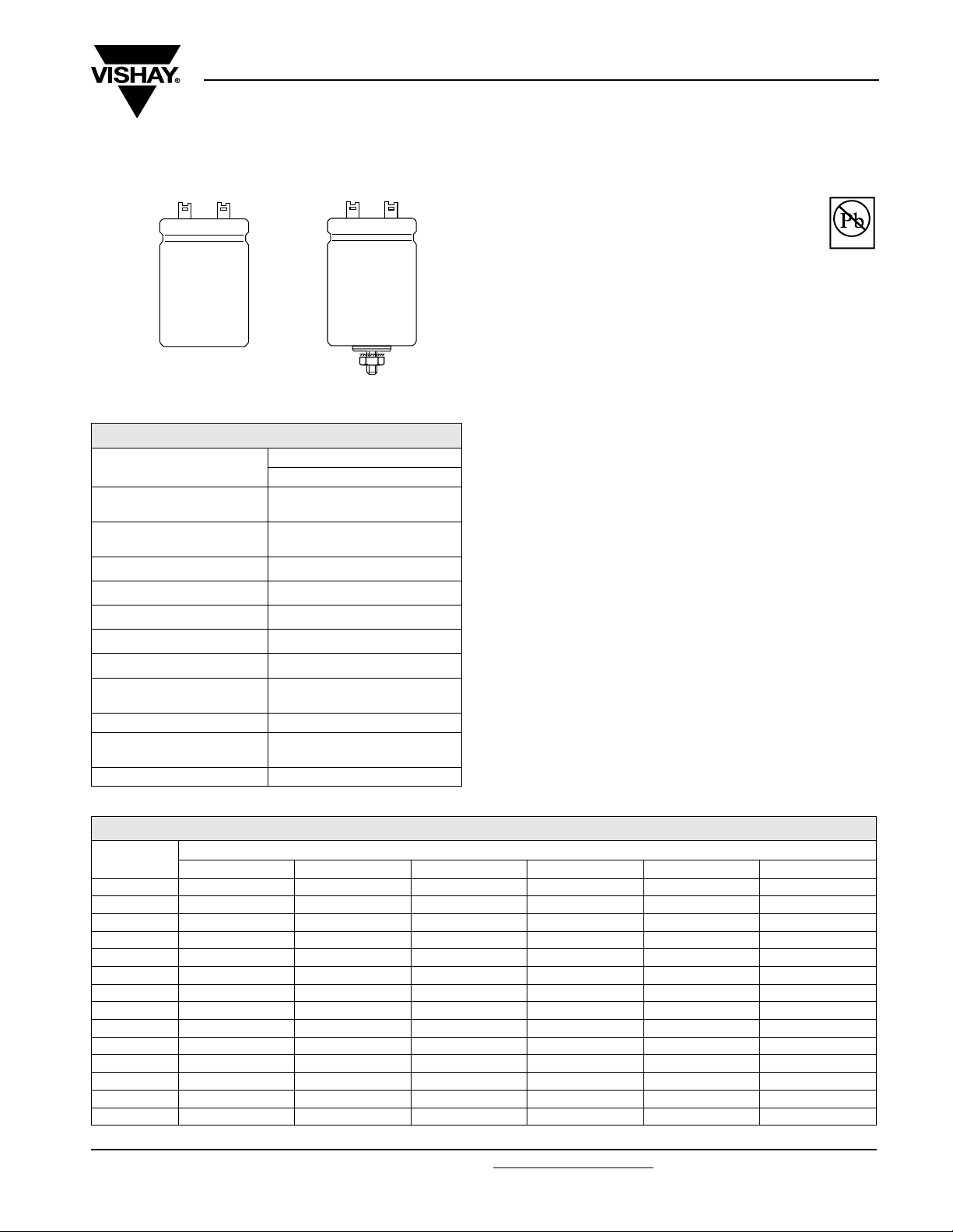
Aluminum Capacitors
Power Solder Lug Style
Component outlines.
QUICK REFERENCE DATA
DESCRIPTION
Nominal case size
(∅D × L in mm)
Rated capacitance range
(E6 series), C
Tolerance on C
Rated voltage range, U
Category temperature range − 40 to + 85 °C
Endurance test at 85 °C 5000 hours
Useful life at 85 °C 15000 hours
Useful life at 40 °C,
1.4 × I
Shelf life at 0 V, 85 °C 500 hours
Based on sectional
specification
Climatic category IEC 60068 40/085/56
applied
R
R
R
R
IEC 60384-4/EN130 300
VAL UE
NV
25 × 30
to 40 × 100
470
to 68000 µF
− 10 to + 30 %
10 to 100 V
200000 hours
Not for new design
FEATURES
• Polarized aluminum electrolytic capacitors,
non-solid electrolyte
• Large types, cylindrical aluminum case,
insulated
• Provided with keyed polarity
• Very long useful life:
15000 hours at 85 °C
• Low ESR, high ripple current capability
• High resistance to shock and vibration
APPLICATIONS
• Computer, telecommunication and industrial systems
• Smoothing and filtering
• Standard and switched mode power supplies
• Energy storage in pulse systems
MARKING
The capacitors are marked (where possible)
with the following information:
• Rated capacitance (in µF)
• Tolerance on rated capacitance, code letter in accordance
with IEC 60062 (Q for - 10/+ 30 %)
• Rated voltage (in V)
• Date code (YYMM)
• Name of manufacturer
• Code for factory of origin
• Polarity of the terminals and ‘−’ sign to indicate the
negative terminal, visible from the top and/or side of the
capacitor
• Code number
• Climatic category in accordance with IEC 60068
Vishay Roederstein
Pb-free
Available
RoHS*
COMPLIANT
SELECTION CHART FOR CR, UR AND RELEVANT NOMINAL CASE SIZES (∅D × L in mm)
(V)
C
R
(µF)
470
680
1000
1500
2200
3300
4700
6800
10000
15000
22000
33000
47000
68000
*Pb containing terminations are not RoHS compliant, exemptions may apply
Document Number: 25129 For technical questions contact: aluminumcaps2@vishay.com
Revision: 20-Jul-06 207
10 16 25 40 63 100
−−−−−25 × 30
−−−− 25 × 40
−−−−25 × 30 30 × 40
−−−25 × 30 25 × 40 35 × 40
−−25 × 30 25 × 40 30 × 40 35 × 50
− 25 × 30 25 × 40 30 × 40 35 × 40 40 × 50
25 × 30 25 × 40 30 × 40 35 × 40 35 × 50 40 × 70
25 × 40 30 × 40 35 × 40 35 × 50 40 × 50 40 × 100
30 × 40 35 × 40 35 × 50 40 × 50 40 × 70 −
35 × 40 35 × 50 40 × 50 40
35 × 50 40 × 50 40 × 70 40 × 100 −−
40 × 50 40 × 70 40 × 100 −−−
40 × 70 40 × 100 −−−−
40 × 100 −−−−−
U
R
× 70 40 × 100 −
www.vishay.com
Page 3
EY
Vishay Roederstein
Aluminum Capacitors
Power Solder Lug Style
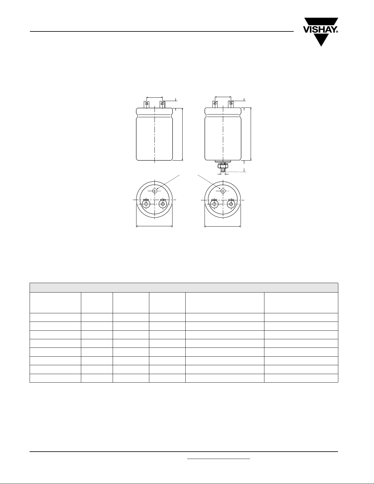
DIMENSIONS in millimeters AND AVAILABLE FORMS
10 ± 0.5
10
“SL”
Dmax.
Lmax.
safety vent
10 ± 0.5
M8
Dmax.
10 ± 1
Lmax.
12 ± 1
“SLB”
*
soldering lug
design T4
DIN 41 497
* The MOQ for SLB version is 5000 pcs.
DIMENSIONS in millimeters, MASS AND PACKAGING QUANTITIES
NOMINAL
CASE SIZE
∅D × L
∅D
MAX
L
MAX
MASS
(g)
PACKAGING QUANTITIES
(units per box)
25 × 30 26 32 ≈ 24 100 290 × 280 × 50
25 × 40 26 42 ≈ 28 100 290 × 280 × 60
30 × 40 31 42 ≈ 38 100 340 × 330 × 60
35 × 40 36 42 ≈ 51 50 390 × 198 × 60
35 × 50 36 52 ≈ 66 50 390 × 198 × 70
40 × 50 41 52 ≈ 82 50 440 × 223 × 70
40 × 70 41 72 ≈ 110 25 230 × 230 × 90
40 × 100 41 102 ≈ 176 25 230 × 230 × 120
CARDBOARD
BOX DIMENSIONS
L × W × H
MOUNTING
When a number of capacitors are connected in a bank, they must not be closer together than 15 mm, when no derating of ripple
current and/or temperature is applied.
www.vishay.com For technical questions contact: aluminumcaps2@vishay.com
Document Number: 25129
208 Revision: 20-Jul-06
Page 4
EY
Aluminum Capacitors
Power Solder Lug Style
ELECTRICAL DATA
SYMBOL DESCRIPTION
C
R
I
R
I
L1
I
L5
ESR max. equivalent series resistance at 100 Hz
Z max. impedance at 10 kHz
Note
1. Unless otherwise specified, all electrical values apply at
T
amb
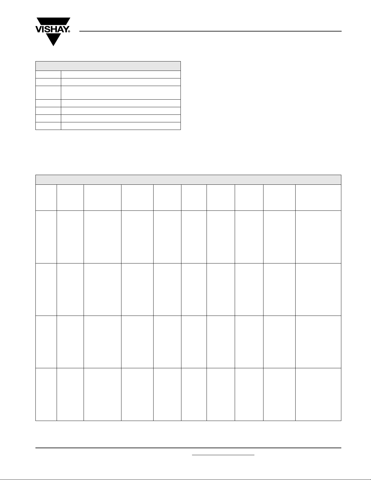
ELECTRICAL DATA AND ORDERING INFORMATION
U
R
(V)
10
16
25
40
rated capacitance at 100 Hz
rated RMS ripple current at 100 Hz,
85 °C or at 20 kHz, 70 °C
max. leakage current after 1 minute at U
max. leakage current after 5 minutes at U
= 20 °C, P = 80 to 120 kPa, RH = 45 to 75 %.
C
R
100 Hz
(µF)
4700 25 × 30 2.4 4.6 0.28 0.10 74 50 EY01AV447C02V
6800 25 × 40 3.2 6.1 0.41 0.14 51 37 EY01AB468C02V
10000 30 × 40 3.8 7.2 0.60 0.20 39 29 EY01BB510C02V
15000 35 × 40 4.1 7.8 0.90 0.30 35 26 EY01CB515C02V
22000 35 × 50 5.0 9.5 1.32 0.44 27 21 EY01CD522C02V
22000 40 × 40 4.2 8.0 1.32 0.44 36 27 EY01DB522C02V
33000 40 × 50 5.0 9.5 1.98 0.66 29 22 EY01DD533C02V
47000 40 × 70 6.8 12.9 2.82 0.94 20 17 EY01DG547C02V
68000 40 × 100 9.2 17.5 4.08 1.36 15 14 EY01DM568C02V
3300 25 × 30 2.4 4.6 0.32 0.11 75 50 EY01AV433D02V
4700 25 × 40 3.1 5.9 0.45 0.15 52 37 EY01AB447D02V
6800 30 × 40 3.7 7.0 0.65 0.22 40 30 EY01BB468D02V
10000 35 × 40 4.1 7.8 0.96 0.32 36 27 EY01CB510D02V
15000 35 × 50 5.0 9.5 1.44 0.48 28 21 EY01CD515D02V
15000 40 × 40 4.2 8.0 1.44 0.48 36 27 EY01DB515D02V
22000 40 × 50 5.0 9.5 2.12 0.71 29 22 EY01DD522D02V
33000 40 × 70 6.7 12.7 3.17 1.06 20 17 EY01DG533D02V
47000 40 × 100 9.1 17.3 4.51 1.51 15 14 EY01DM547D02V
2200 25 × 30 2.3 4.4 0.33 0.11 78 52 EY01AV422E02V
3300 25 × 40 3.1 5.9 0.49 0.17 53 38 EY01AB433E02V
4700 30 × 40 3.7 7.0 0.70 0.24 42 31 EY01BB447E02V
6800 35 × 40 4.1 7.8 1.02 0.34 37 28 EY01CB468E02V
10000 35 × 50 5.0 9.5 1.50 0.50 28 21 EY01CD510E02V
10000 40 × 40 4.2 8.0 1.50 0.50 36 27 EY01DB510E02V
15000 40 × 50 5.0 9.5 2.25 0.75 29 22 EY01DD515E02V
22000 40 × 70 6.8 12.9 3.30 1.10 20 17 EY01DG522E02V
33000 40 × 100 9.2 17.5 4.95 1.65 15 14 EY01DM533E02V
1500 25 ×
2200 25 × 40 2.7 5.1 0.53 0.18 76 51 EY01AB422G02V
3300 30 × 40 3.3 6.3 0.79 0.27 57 41 EY01BB433G02V
4700 35 × 40 3.8 7.2 1.13 0.38 48 35 EY01CB447G02V
6800 35 × 50 4.7 8.9 1.64 0.55 36 27 EY01CD468G02V
6800 40 × 40 4.1 7.8 1.64 0.55 45 33 EY01DB468G02V
10000 40 × 50 4.9 9.3 2.40 0.80 35 27 EY01DD510G02V
15000 40 × 70 6.6 12.5 3.60 1.20 25 20 EY01DG515G02V
22000 40 × 100 9.0 17.1 5.28 1.76 18 16 EY01DM522G02V
NOMINAL
CASE SIZE
∅D × L
(mm)
30 2.0 3.8 0.36 0.12 112 68 EY01AV415G02V
100 Hz
85 °C
I
(A)
R
R
R
I
R
20 kHz
70 °C
(A)
I
L1
1min
(mA)
Vishay Roederstein
ORDERING EXAMPLE
EY01: 10000 µF / 25 V
Version 01: (no stud mounting)
Size: 35 mm x 50 mm
Ordering code: EY01CD510E02V
EY02: 10000 µF / 25 V
Version 02: (stud mounting)*
Size: 35 mm x 50 mm
Ordering code: EY02CD510E01V
* MOQ for Version 02: 5000 pcs.
I
L5
5min
(mA)
ESR
100 Hz
(mΩ)
10 kHz
Z
(mΩ)
CATALOG
NUMBER
Document Number: 25129 For technical questions contact: aluminumcaps2@vishay.com
Revision: 20-Jul-06 209
www.vishay.com
Page 5
EY
Vishay Roederstein
Aluminum Capacitors
Power Solder Lug Style
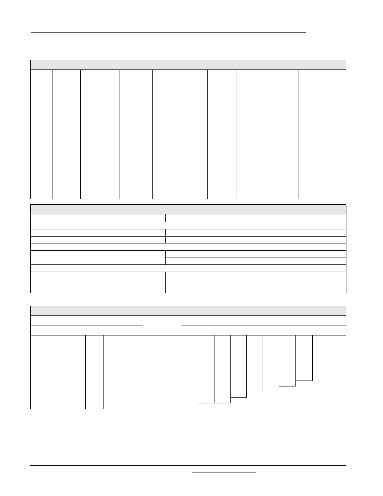
ELECTRICAL DATA AND ORDERING INFORMATION
U
(V)
C
R
R
100 Hz
(µF)
NOMINAL
CASE SIZE
∅D × L
(mm)
1000 25 × 30 1.8 3.4 0.38 0.13 122 74 EY01AV410J02V
1500 25 × 40 2.5 4.7 0.57 0.19 83 54 EY01AB415J02V
2200 30 × 40 3.1 5.9 0.83 0.28 57 41 EY01BB422J02V
3300 35 × 40 3.6 6.8 1.25 0.42 48 35 EY01CB433J02V
63
4700 35 × 50 4.4 8.3 1.78 0.60 36 27 EY01CD447J02V
4700 40 × 40 3.8 7.2 1.78 0.60 45 33 EY01DB447J02V
6800 40 × 50 4.7 8.9 2.57 0.86 35 27 EY01DD468J02V
10000 40 × 70 6.2 11.8 3.78 1.26 25 20 EY01DG510J02V
15000 40 × 100 8.5 16.1 5.67 1.89 18 16 EY01DM515J02V
470 25 × 30 1.4 2.7 0.28 0.10 247 172 EY01AV347L02V
680 25 × 40 1.9 3.6 0.41 0.14 170 116 EY01AB368L02V
1000 30 × 40 2.5 4.7 0.60 0.20 123 88 EY01BB410L02V
1500 35 × 40 3.1 5.8 0.90 0.30 94 71 EY01CB415L02V
100
2200 35 × 50 3.9 7.4 1.32 0.44 69 55 EY01CD422L02V
2200 40 × 40 3.6 6.8 1.32 0.44 81 65 EY01DB422L02V
3300 40 × 50 4.6 8.7 1.98 0.66 59 48 EY01DD433L02V
4700 40 × 70 6.2 11.7 2.82 0.94 42 36 EY01DG447L02V
6800 40 × 100 8.2 15.5 4.08 1.36 32 28 EY01DM468L02V
ADDITIONAL ELECTRICAL DATA
PARAMETER CONDITIONS VALUE
Voltag e
Surge voltage ≤ 250 V versions U
Reverse voltage U
Current
Leakage current after 1 minute at U
Inductance
Equivalent series inductance (ESL) case ∅D = 25 mm max. 25 nH
I
R
100 Hz
85 °C
(A)
I
R
20 kHz
70 °C
(A)
after 5 minutes at U
I
L1
1min
(mA)
5min
R
R
I
L5
(mA)
ESR
100 Hz
(mΩ)
case ∅D = 30 and 35 mm max. 30 nH
case ∅D = 40 mm max. 35 nH
Z
10 kHz
(mΩ)
=1.15× U
s
rev
≤ 1V
R
IL1≤ 0.006 CR× UR+4µA
IL5≤ 0.002 CR× UR+4µA
CATALOG
NUMBER
LIFETIME TABLE rated voltage: ≤ 100 V
INTERRELATION BETWEEN ALTERNATING CURRENT, AMBIENT TEMPERATURE AND LIFETIME
I/IR (FREQUENCY DEPENDENT)
FREQUENCY [Hz]
50 100 250 500 1000 > 2500 ΔT
0.19 0.20 0.21 0.22 0.22 0.23 0.2 63 40 26 17 11 7.3 5.0 3.4 2.3 1.63
0.38 0.40 0.42 0.43 0.45 0.47 0.7 55 35 23 15 9.9 6.7 4.5 3.1 2.2 1.51
0.56 0.60 0.63 0.65 0.67 0.70 1.5 45 29 19 13 8.5 5.7 3.9 2.7 1.9 1.33
0.75 0.80 0.84 0.86 0.89 0.94 2.5 35 23 15 10 6.9 4.7 3.3 2.3 1.6 1.13
0.94 1.00 1.05 1.08 1.12 1.17 3.8 26 17 12 7.9 5.4 3.7 2.6 1.8 1.3 1.00
1.13 1.20 1.26 1.29 1.34 1.41 5.4 18 13 8.6 5.9 4.1 2.9 2.0 1.4 1.0
1.31 1.40 1.47 1.51 1.56 1.64 7.4 13 8.7 6.1 4.2 3.0 2.1 1.5 1.1
1.50 1.60 1.68 1.72 1.79 1.87 9.6 8.3 5.9 4.2 3.0 2.1 1.5 1.1
1.69 1.80 1.89 1.94 2.01 2.11 12 5.4 3.9 2.8 2.0 1.4 1.0 combination
1.88 2.00 2.10 2.15 2.23 2.34 15 3.4 2.5 1.8 1.3 not
2.06 2.20 2.30 2.37 2.45 2.58 18 2.1 1.5 1.1 permitted
2.25 2.40 2.51 2.58 2.68 2.81 21 1.2
IR100 Hz alternating current [A] at upper category temperature TUC taken from data sheet.
I User current [A].
Ambient temperature of capacitor [°C].
T
a
Surface temperature rise of capacitor caused by AC load [°C].
ΔT
ο
L Lifetime multiplier.
www.vishay.com For technical questions contact: aluminumcaps2@vishay.com Document Number: 25129
210 Revision: 20-Jul-06
SURFACE
TEMPERATURE
RISE
[°C] 40 45 50 55 60 65 70 75 80 85
ο
LIFETIME MULTIPLIER L (depending on I/I
AMBIENT TEMPERATURE T
[°C]
a
and Ta)
R
 Loading...