

Page 1

6121 Baker Road,
Suite 108
Minnetonka, MN 55345
www.chtechnology.com
Phone (952) 933-6190
Fax (952) 933-6223
1-800-274-4284
Thank you for downloading this document from C&H Technology, Inc.
Please contact the C&H Technology team for the following questions -
Technical
Application
Assembly
Availability
Pricing
Phone – 1-800-274-4284
E-Mail – sales@chtechnology.com
www.chtechnology.com - SPECIALISTS IN POWER ELECTRONIC COMPONENTS AND ASSEMBLIES - www.chtechnology.com
Page 2
ET
Vishay ESTA
Document Number: 13014
Revision 04-Jan-02
www.vishay.com
3
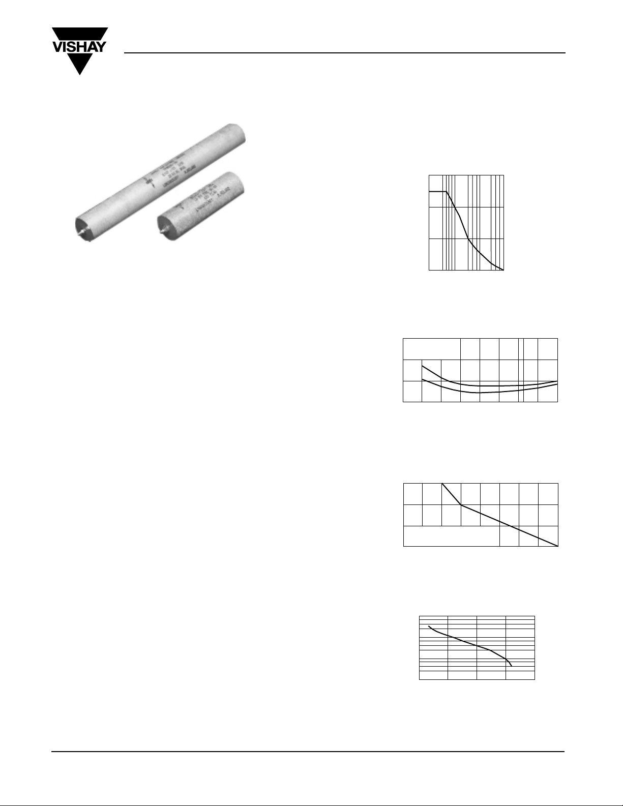
TYPE ET
These capacitors are manufactured using a mixed
dielectric material that consists of polyester/polypropylene
film and capacitor tissue. They are impregnated and
filled with a mineral oil. The container is a Synthetic
Resin Bonded Paper tube sealed at both ends with
resin assuring hermetic sealing. The capacitors are
terminated with M5 *12mm studs or tinned copper wire.
Note: The impregnant used is a non toxic highly refined,
purified and inhibited mineral oil.
APPLICATIONS
The ET range is specifically designed for high voltage
filters and can be successfully used in the following
applications:
• By-pass
• Coupling
• Filter applications
• X-ray power supplies
• Electrostatic air deaners
TEMPERATURE RANGE
Temperature range is – 55°C to + 85°C. Derating is
required for operation at higher temperatures.
TEMPERATURE COEFFICIENT
Capacitance will increase by 2% per 100°C temperature
rise.
CAPACITANCE RANGE
0.0005µF - 2µF. The tolerance is ± 10%. Other
tolerances are available on request. Nominal values
measured at 1kHz.
VOLTAGE RANGE
1000VDC - 70kVDC
POWER FACTOR
The power factor is variable, and is a function of
temperature and frequency see fig.2. Nominal value
< 0.5% at 20°C
DC Filter Capacitors
RIPPLE
The sum of the peak ripple voltage and the DC voltage
should not exceed the rated voltage. Refer to graph fig.1
for permissible peak-to-peak ripple voltage as a
percentage of rated voltage for various frequencies.
DIELECTRIC RESISTANCE
(Parallel resistance) is indicated by the graph of insulance
(MΩ x µF) vs temperature fig.3. The insulance (MΩ x µF)
is nominally 10000s at + 20°C. (Measurements taken
after 1 minute with an applied voltage of 500V)
LIFE EXPECTANCY
ET type capacitors are designed for a life exceptancy of
5000h at 65 °C. To achieve the same life expectancy at
85°C derate to 60% of rated voltage fig.4.
WEIGHT
The approximate weight in grams may be calculated by
multiplying the volume of the capacitor container by 1.2 x
10-3.
FIG 1
FIG 2
FIG 3
FIG 4
30
20
E
L
P
P
I
R
%
10
0
10 100 1000
Hz
10000
at 20°C
POWER FACTOR
vs
TEMPERATURE
2%
50H
1kH
z
z
- 20
040
65
80°C
1%
0%
D
F
M
4
10
x
S
M
H
3
O
10
G
INSULANCE VS TEMPERATURE
E
M
10
2
TYPICAL VALUES
- 40
040
80°C
S
R
U
O
5
H
10
4
10
3
10
50
150°
100
RATED VOLTAGE
Page 3

ET
Vishay ESTA
Document Number: 13014
Revision 04-Jan-02
www.vishay.com
4
PART DIMENSIONS
NUMBER µF L mm D mm
1000VDC WKG
ET10-103 0.01* 42 17
ET10-203 0.02* 42 17
ET10-503 0.05 48 17
ET10-254 0.25 60 22
ET10-504 0.5 70 30
ET10-205 2.0 110 35
1500VDC WKG
ET15-103 0.01* 42 17
ET15-203 0.02* 42 20
ET15-254 0.25 60 30
ET15-504 0.5 110 25
ET15-105 1.0 110 35
ET15-205 2.0 110 42
2000VDC WKG
ET20-103 0.01* 48 17
ET20-503 0.05 60 17
ET20-104 0.1 60 22
ET20-254 0.25 60 30
ET20-504 0.5 75 35
3000VDC WKG
ET30-502 0.005* 42 17
ET30-103 0.01* 42 20
ET30-203 0.02 48 20
ET30-503 0.05 55 25
ET30-104 0.1 55 30
ET30-254 0.25 60 35
ET30-504 0.5 75 42
ET30-105 1.0 110 42
4000VDC WKG
ET40-102 0.001* 42 17
ET40-502 0.005* 42 17
ET40-503 0.05 60 22
ET40-103 0.01 42 20
ET40-104 0.1 60 30
ET40-504 0.5 95 42
5000VDC WKG
ET50-102 0.001* 42 17
ET50-202 0.002* 42 17
ET50-502 0.005* 42 20
ET50-103 0.01 48 20
ET50-203 0.02 48 22
ET50-503 0.05 60 25
ET50-104 0.1 75 30
ET50-254 0.25 95 35
ET50-504 0.5 110 42
TEST VOLTAGE
Terminal/terminal (Vt/t)
For DC rating < 20kV
Vt/t = 2.0 x rated voltage 60s
For DC rating > 20kV
Vt/t = 1.5 x rated voltage 60s
TERMINATIONS
Add suffix W to part No. To indicate wire terminations.
CAPACITANCE
Capacitance tolerance of 20% is standard with those
marked *.
DC Filter Capacitors
• Dimensions in millimeters
12
D
L
12
5
Page 4

ET
Vishay ESTA
Document Number: 13014
Revision 04-Jan-02
www.vishay.com
5
PART DIMENSIONS
NUMBER µF L mm D mm
25KVDC WKG
ET250-501 0.0005* 145 17
ET250-102 0.001* 145 20
ET250-502 0.005 175 30
ET250-103 0.01 175 35
ET250-503 0.05 300 42
30KkVDC WKG
ET300-501 0.0005* 170 17
ET300-102 0.001* 170 20
ET300-202 0.002 170 25
ET300-502 0.005 205 30
ET300-103 0.01 205 35
ET300-203 0.02 280 35
ET300-303 0.03 280 42
40KVDC WKG
ET400-102 0.001* 210 20
ET400-202 0.002 275 20
ET400-103 0.01 275 42
50KVDC WKG
ET500-501 0.0005* 275 22
ET500-102 0.001* 275 22
ET500-202 0.002 340 22
ET500-502 0.005 340 35
ET500-103 0.01 340 42
60KVDC WKG
ET600-102 0.001* 330 25
ET600-152 0.0015 330 30
PART DIMENSIONS
NUMBER µF L mm D mm
6000VDC WKG
ET60-102 0.001* 55 17
ET60-202 0.002* 55 17
ET60-502 0.005* 65 17
ET60-103 0.01 65 20
ET60-203 0.02 80 20
ET60-503 0.05 100 25
ET60-104 0.1 100 35
ET60-254 0.25 135 42
8000VDC WKG
ET80-502 0.005* 65 20
ET80-103 0.01 80 20
ET80-503 0.05 105 35
ET80-104 0.1 105 42
ET80-254 0.25 170 42
10KVDC WKG
ET100-102 0.001* 65 17
ET100-502 0.005* 65 22
ET100-103 0.01 80 22
ET100-203 0.02 80 30
ET100-503 0.05 105 35
ET100-104 0.1 170 35
ET100-254 0.25 205 42
12KVDC WKG
ET120-202 0.002* 95 20
ET120-502 0.005* 95 30
ET120-103 0.01 115 30
ET120-203 0.02 115 35
ET120-503 0.05 180 35
ET120-104 0.1 180 42
15KVDC WKG
ET150-102 0.001* 95 17
ET150-202 0.002* 95 20
ET150-502 0.005* 110 20
ET150-103 0.01 110 30
ET150-203 0.02 110 35
ET150-503 0.05 150 42
ET150-104 0.1 245 42
20KVDC WKG
ET200-102 0.001* 115 22
ET200-502 0.005* 145 25
ET200-103 0.01 145 30
ET200-203 0.02 195 30
ET200-503 0.05 245 42
ET200-104 0.1 320 42
DC Filter Capacitors
NOTE: Non standard size containers can be supplied on request.
 Loading...