

Page 1

6121 Baker Road,
Suite 108
Minnetonka, MN 55345
www.chtechnology.com
Phone (952) 933-6190
Fax (952) 933-6223
1-800-274-4284
Thank you for downloading this document from C&H Technology, Inc.
Please contact the C&H Technology team for the following questions -
Technical
Application
Assembly
Availability
Pricing
Phone – 1-800-274-4284
E-Mail – sales@chtechnology.com
www.chtechnology.com - SPECIALISTS IN POWER ELECTRONIC COMPONENTS AND ASSEMBLIES - www.chtechnology.com
Page 2
EPR
Vishay ESTA
Document Number: 13016
Revision 04-Jan-02
www.vishay.com
10
High Voltage DC Capacitors
TYPE EPR
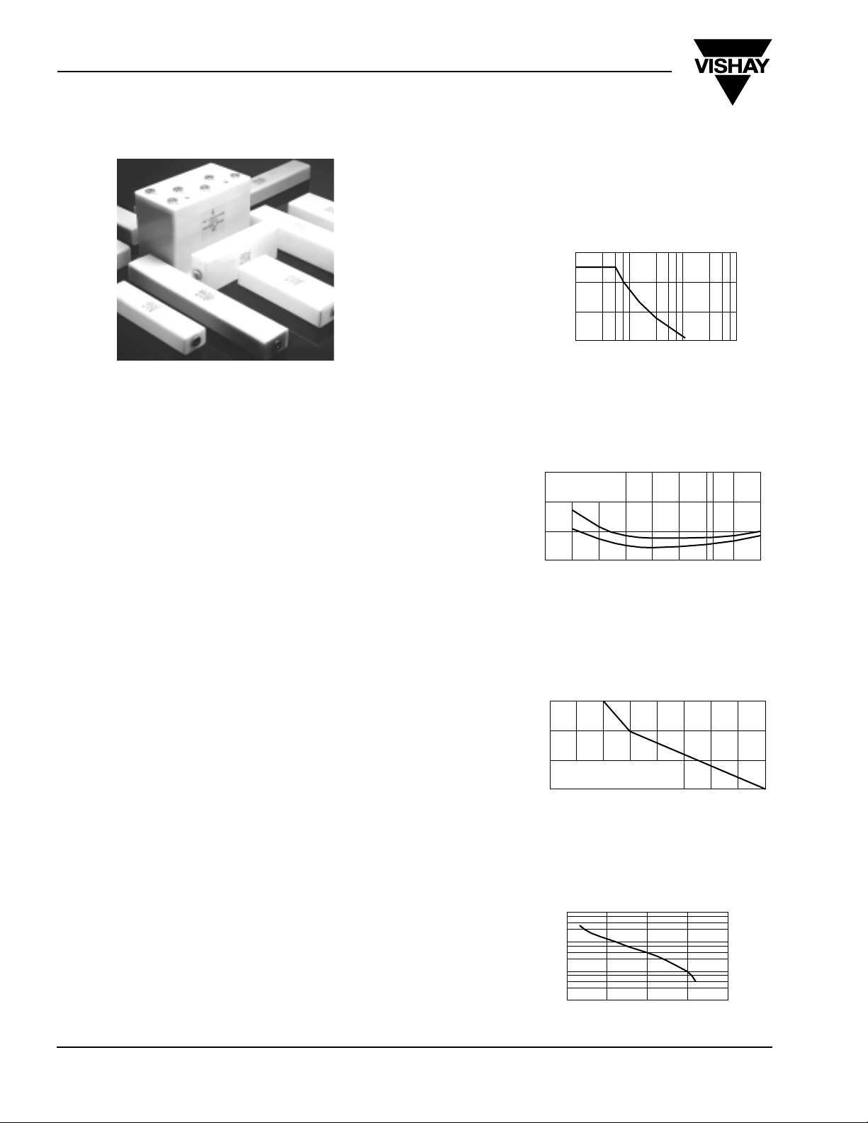
The EPR range of capacitors are manufactured using a
mixed dielectric material that consists of polyester
/polypropylene film and capacitor tissue. They are
impregnated and filled with a mineral oil. The container
is a robust rectangular polypropylene case. The internal
construction is designed to prevent movement when the
capacitor is subjected to mechanical shock or vibration.
An inert welding process ensures hermetic sealing.
Standard terminations are M10 threaded inserts which
eliminates the necessity for large voltage terminals. The
case has an extremely low affinity for moisture and is
resistant to virtually all electrical environments.
Brackets can be welded on as required.
Note: The impregnant used is a non toxic highly purified
and inhibited mineral oil.
APPLICATIONS
The EPR range is designed specifically for DC
applications such as filters:
• By-pass
• Coupling
• Rapid discharge
• Pulse forming networks
• Radar
• Laser
• X-ray equipment
TEMPERATURE RANGE
Temperature range is - 40°C to + 85°C. Derating is
required for operation at higher temperatures.
TEMPERATURE COEFFICIENT
Capacitance will increase by 2% per 100°C temperature
rise.
CAPACITANCE RANGE
0.002µF - 2µF. The tolerance is ± 10%. Other tolerance
are available on request. Normal values measured at
1kHz.
POWER FACTOR
The power factor is variable, and is a function of
temperature and frequency see fig.2. Nominal value
< 0.5% at 20°C
RIPPLE
The sum of the peak ripple voltage and the DC voltage
should not exceed the rated voltage. Refer to graph fig.1
for permissible peak-to-peak ripple voltage as a
percentage of rated voltage for various frequencies.
DIELECTRIC RESISTANCE
(
Parallel resistance) is indicated by the graph of
insulance (MΩ x µF) vs temperature fig.3. The insulance
(MΩ x µF) is nominally 10000s at + 20°C. (Measurements
taken after 1 minute with an applied voltage of 500V)
LIFE EXPECTANCY
EPR type capacitors are designed for a life exceptancy
of 50000 hours at 65 °C. To achieve the same life
expectancy at 85°C derate to 60% of rated voltage fig.4.
FIG 1
FIG 2
FIG 3
FIG 4
E
30
L
P
P
I
R
20
%
10
0
10 100 1000
10000
FREQUENCY Hz
at 20°C
POWER FACTOR
vs
TEMPERATURE
2%
50H
1kH
z
z
- 20
040
80
65
1%
0%
D
F
M
4
10
x
S
M
H
3
O
10
G
INSULANCE VS TEMPERATURE
E
M
10
2
TYPICAL VALUES
- 40
040
80°C
S
R
U
O
5
H
10
4
10
3
10
50
150°
100
RATED VOLTAGE
Page 3

EPR
Vishay ESTA
Document Number: 13016
Revision 04-Jan-02
www.vishay.com
11
DC
PART µF KILO- A B C
NUMBER VOLTS
EPR150-104 0.1 15 75 75 142
EPR300-504 0.5 30 130 220 185
EPR500-103 0.01 50 70 90 245
EPR500-504 0.5 50 175 235 280
EPR750-503 0.05 75 80 110 365
EPR750-104 0.1 75 115 130 365
EPR750-254 0.25 75 175 190 365
EPR1000-253 0.025 100 80 90 420
EPR1000-403 0.04 100 120 200 285
EPR1000-104 0.1 100 125 175 445
EPR2000-502 0.005 200 90 90 385
EPR3000-252 0.0025 300 70 95 555
VOLTAGE RANGE
1kVDC - 300kVDV
TEST VOLTAGE
Terminal/terminal (Vt/t)
For DC rating < 20kV
Vt/t = 2.0 x rated voltage 60s
For DC rating > 20kV
Vt/t = 1.5 x rated voltage 60s
High Voltage DC Capacitors
C
6mm
A
B
 Loading...