

Page 1
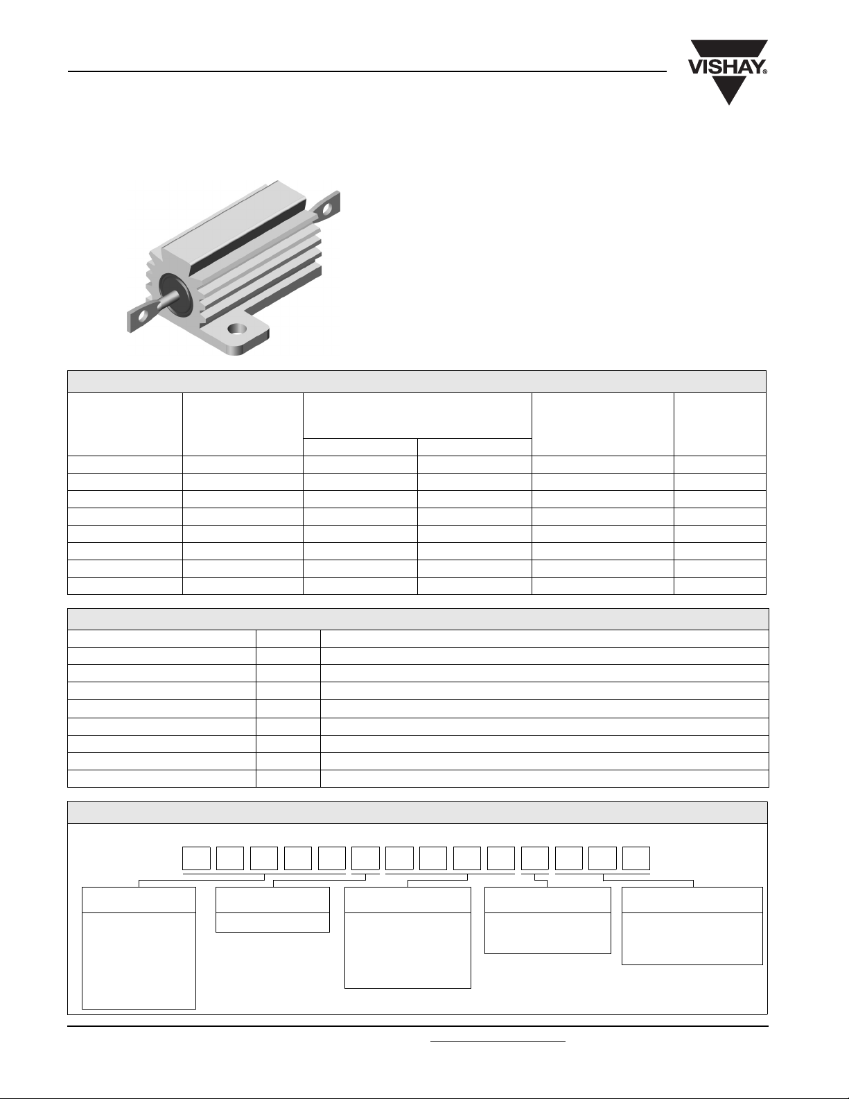
ERH, ENH
Vishay Dale
Wirewound Resistors, Military/Established Reliability
MIL-PRF-39009 Qualified, Type RER, R Level
FEATURES
• Aluminum heat sink housing
• Molded construction for total environmental protection
• Qualified to MIL-PRF-39009
• Complete welded construction
• Available in non-inductive styles (type ENH) with Aryton-
Perry winding for lowest reactive components
• Mounts on chassis to utilize heat-sink effect
STANDARD ELECTRICAL SPECIFICATIONS
POWER RATING
P
MODEL
ENH-5 RER40 5 3 1 - 1.65K 3.3
ENH-10 RER45 10 6 1 - 2.8K 8.8
ENH-25 RER50 20 8 1 - 6.04K 16.5
ENH-50 RER55 30 10 1 - 4.99K 35
ERH-5 RER60 5 3 0.10 - 3.32K 3
ERH-10 RER65 10 6 0.10 - 5.62K 6
ERH-25 RER70 20 8 0.10 - 12.1K 13
ERH-50 RER75 30 10 0.10 - 39.2K 28
MIL-PRF-39009
TYPE
MOUNTED FREE AIR
25 °C
W
MILITARY
RESISTANCE RANGE
± 1 %
Ω
WEIGHT
(typical)
g
TECHNICAL SPECIFICATIONS
PARAMETER UNIT ERH, ENH RESISTOR CHARACTERISTICS
Temperature Coefficient ppm/°C ± 100 for 0.1 Ω to 0.99 Ω, ± 50 for 1 Ω to 19.9 Ω, ± 20 for 20 Ω and above
Dielectric Withstanding Voltage V
Short Time Overload - 5 x rated power for 5 s
Maximum Working Voltage V
Insulation Resistance Ω 10 000 MΩ minimum dry, 1000 MΩ minimum after moisture test
Terminal Strength lb 5 pull for ERH-5 and ERH-10, 10 pull for ERH-25 and ERH-50
Solderability - Meets requirements of ANSI J-STD-002
Operating Temperature Range °C - 55 to + 250
AC
1000 for ERH-5, ERH-10 and ERH-25, 2000 for ERH-50
1/2
(P x R)
GLOBAL PART NUMBER INFORMATION
Global/Military Part Numbering: RER65F1001RC02
65F1 01R0ER C02R
MIL TYPE TOLERANCE CODE RESISTANCE VALUE FAILURE RATE PACKAGING CODE
RER40
RER45
RER50
RER55
RER60
RER65
RER70
RER75
www.vishay.com For technical questions, contact: ww2bresistors@vishay.com
160 Revision: 29-May-08
F = ± 1.0 % 3 digit significant figure,
followed by a multiplier
49R9 = 49.9 Ω
1000 = 100 Ω
1001 = 1000 Ω
M = 1.0 %/1000 h
P = 0.1 %/1000 h
R = 0.01 %/1000 h
C02 = Tin/lead,
CSL = Tin/lead, card pack,
card pack
single lot date code
Document Number: 30200
Page 2
ERH, ENH
Wirewound Resistors, Military/Established Reliability
MIL-PRF-39009 Qualified, Type RER, R Level
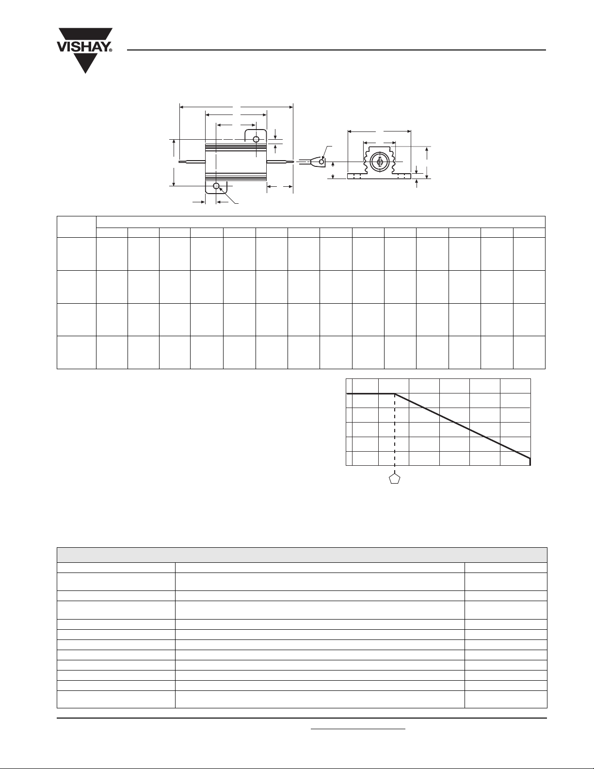
DIMENSIONS
B
MODEL
ERH-5
ENH-5
ERH-10
ENH-10
ERH-25
ENH-25
ERH-50
ENH-50
ABCD E F GH J K L MN P
0.444
± 0.005
[11.280
± 0.127]
0.562
± 0.005
[14.270
± 0.127]
0.719
± 0.005
[18.260
± 0.127]
1.562
± 0.005
[39.670
± 0.127]
0.490
± 0.005
[12.450
± 0.127]
0.625
± 0.005
[15.880
± 0.127]
0.781
± 0.005
[19.840
± 0.127]
0.844
± 0.005
[21.440
± 0.127]
0.600
± 0.031
[15.240
± 0.787]
0.750
± 0.031
[19.050
± 0.787]
1.062
± 0.031
[26.970
± 0.787]
1.968
± 0.031
[49.990
± 0.787]
1.125
± 0.062
[28.580
± 1.570]
1.375
± 0.062
[34.930
± 1.570]
1.938
± 0.062
[49.230
± 1.570]
2.781
± 0.062
[70.640
± 1.570]
MATERIAL SPECIFICATIONS
Element: Copper-nickel alloy or nickel-chrome alloy,
depending on resistance value
Core: Ceramic, steatite or alumina, depending on physical
size
Encapsulant: Silicone molded construction
Housing: Aluminum with hard anodic coating
End Caps: Stainless steel
Standard Terminals: Tinned Copperweld
Part Marking: Source code, JAN, military PIN, date/lot code
POWER RATING
Vishay ERH and ENH resistor wattage ratings are based on
mounting to the proper heat sink.
ERH-5 and ERH-10: 4" x 6" x 2" x 0.040" thick aluminum
chassis
ERH-25 and ERH-50: 5" x 7" x 2" x 0.040" thick aluminum
chassis
K
± 0.015
± 0.381]
± 0.015
[10.670
± 0.381]
± 0.015
[13.970
± 0.381]
± 0.015
[16.000
± 0.381]
®
D
C
A
P
L
DIMENSIONS in inches [millimeters]
0.334
[8.480
0.420
0.550
0.630
0.646
± 0.015
[16.410
± 0.381]
0.800
± 0.015
[20.320
± 0.381]
1.080
± 0.015
[27.430
± 0.381]
1.140
± 0.015
[28.960
± 0.381]
Vishay Dale
0.133
± 0.010
[3.380
± 0.254]
0.165
± 0.010
[4.190
± 0.254]
0.231
± 0.010
[5.870
± 0.254]
0.260
± 0.010
[6.600
± 0.254]
- 50
F
E
0.078
± 0.010
[1.980
± 0.254]
0.093
± 0.010
[2.360
± 0.254]
0.172
± 0.010
[4.370
± 0.254]
0.196
± 0.010
[4.980
± 0.254]
25
H
G
0.093
± 0.005
[2.360
± 0.127]
0.094
± 0.005
[2.390
± 0.127]
0.125
± 0.005
[3.180
± 0.127]
0.125
± 0.005
[3.180
± 0.127]
0.078
± 0.015
[1.980
± 0.381]
0.102
± 0.015
[2.590
± 0.381]
0.115
± 0.015
[2.920
± 0.381]
0.107
± 0.015
[2.720
± 0.381]
AMBIENT TEMPERATURE IN °C
M
0.320
± 0.015
[8.130
± 0.381]
0.390
± 0.015
[9.910
± 0.381]
0.546
± 0.015
[13.870
± 0.381]
0.610
± 0.015
[15.490
± 0.381]
N
J
0.065
± 0.010
[1.650
± 0.254]
0.075
± 0.010
[1.900
± 0.254]
0.075
± 0.010
[1.900
± 0.254]
0.088
± 0.010
[2.240
± 0.254]
120
100
80
60
40
RATED POWER IN %
20
0
- 55 0 50 100 150 200 250
Derating
APPLICABLE MIL SPECIFICATION
MIL-PRF-39009: This is the military specification covering
housed chassis mount established reliability power
wirewound resistors. Vishay ERH and ENH resistors are
listed as qualified on the MIL-PRF-39009 QPL.
0.050
± 0.005
[1.270
± 0.127]
0.085
± 0.005
[2.160
± 0.127]
0.085
± 0.005
[2.160
± 0.127]
0.085
± 0.005
[2.160
± 0.127]
0.266
± 0.062
[6.760
± 1.570]
0.312
± 0.062
[7.920
± 1.570]
0.438
± 0.062
[11.130
± 1.570]
0.438
± 0.062
[11.130
± 1.570]
PERFORMANCE
TEST CONDITIONS OF TEST TEST LIMITS
Low Temperature Operation
Short Time Overload 5 x rated power for 5 s ± (0.3 % + 0.01 Ω) ΔR
Dielectric Withstanding Voltage
Low Temperature Storage - 55 °C for 24 h ± (0.3 % + 0.01 Ω) ΔR
High Temperature Exposure 250 °C for 2000 h ± (1.0 % + 0.01 Ω) ΔR
Moisture Resistance MIL-STD-202, Method 106 ± (0.5 % + 0.01 Ω) ΔR
Shock, Specified Pulse MIL-STD-202, Method 213, condition 1 ± (0.2 % + 0.01 Ω) ΔR
Vibration, High Frequency MIL-STD-202, Method 204, condition D ± (0.2 % + 0.01 Ω) ΔR
Load Life 2000 h at rated power, + 25 °C, 1.5 h “ON”, 0.5 h “OFF” ± (1.0 % + 0.01 Ω) ΔR
Extended Life 10 000 h at rated power, + 25 °C, 1.5 h “ON”, 0.5 h “OFF” ± (2.0 % + 0.01 Ω) ΔR
Terminal Strength
Document Number: 30200 For technical questions, contact: ww2bresistors@vishay.com
Revision: 29-May-08 161
Apply rated power until thermal stability, remove power subject to air
temperature of - 55 °C for 15 to 30 min
1000 V
1 min duration
MIL-STD-202, Method 211, condition A
5 pound (RER40, 45, 60, 65), 10 pound (RER50, 55, 70, 75)
(RER 40, 45, 50, 60, 65, 70), 2000 V
rms
(RER55 and 75),
rms
± (0.5 % + 0.01 Ω) ΔR
± (0.2 % + 0.01 Ω) ΔR
± (0.2 % + 0.01 Ω) ΔR
www.vishay.com
Page 3

Legal Disclaimer Notice
Vishay
Disclaimer
All product specifications and data are subject to change without notice.
Vishay Intertechnology, Inc., its affiliates, agents, and employees, and all persons acting on its or their behalf
(collectively, “Vishay”), disclaim any and all liability for any errors, inaccuracies or incompleteness contained herein
or in any other disclosure relating to any product.
Vishay disclaims any and all liability arising out of the use or application of any product described herein or of any
information provided herein to the maximum extent permitted by law. The product specifications do not expand or
otherwise modify Vishay’s terms and conditions of purchase, including but not limited to the warranty expressed
therein, which apply to these products.
No license, express or implied, by estoppel or otherwise, to any intellectual property rights is granted by this
document or by any conduct of Vishay.
The products shown herein are not designed for use in medical, life-saving, or life-sustaining applications unless
otherwise expressly indicated. Customers using or selling Vishay products not expressly indicated for use in such
applications do so entirely at their own risk and agree to fully indemnify Vishay for any damages arising or resulting
from such use or sale. Please contact authorized Vishay personnel to obtain written terms and conditions regarding
products designed for such applications.
Product names and markings noted herein may be trademarks of their respective owners.
Document Number: 91000 www.vishay.com
Revision: 18-Jul-08 1
 Loading...