

Page 1

6121 Baker Road,
Suite 108
Minnetonka, MN 55345
www.chtechnology.com
Phone (952) 933-6190
Fax (952) 933-6223
1-800-274-4284
Thank you for downloading this document from C&H Technology, Inc.
Please contact the C&H Technology team for the following questions -
Technical ● Application ● Assembly ● Availability ● Pricing
Phone – 1-800-274-4284
E-Mail – sales@chtechnology.com
www.chtechnology.com - SPECIALISTS IN POWER ELECTRONIC COMPONENTS AND ASSEMBLIES
-
www.chtechnology.com
Page 2
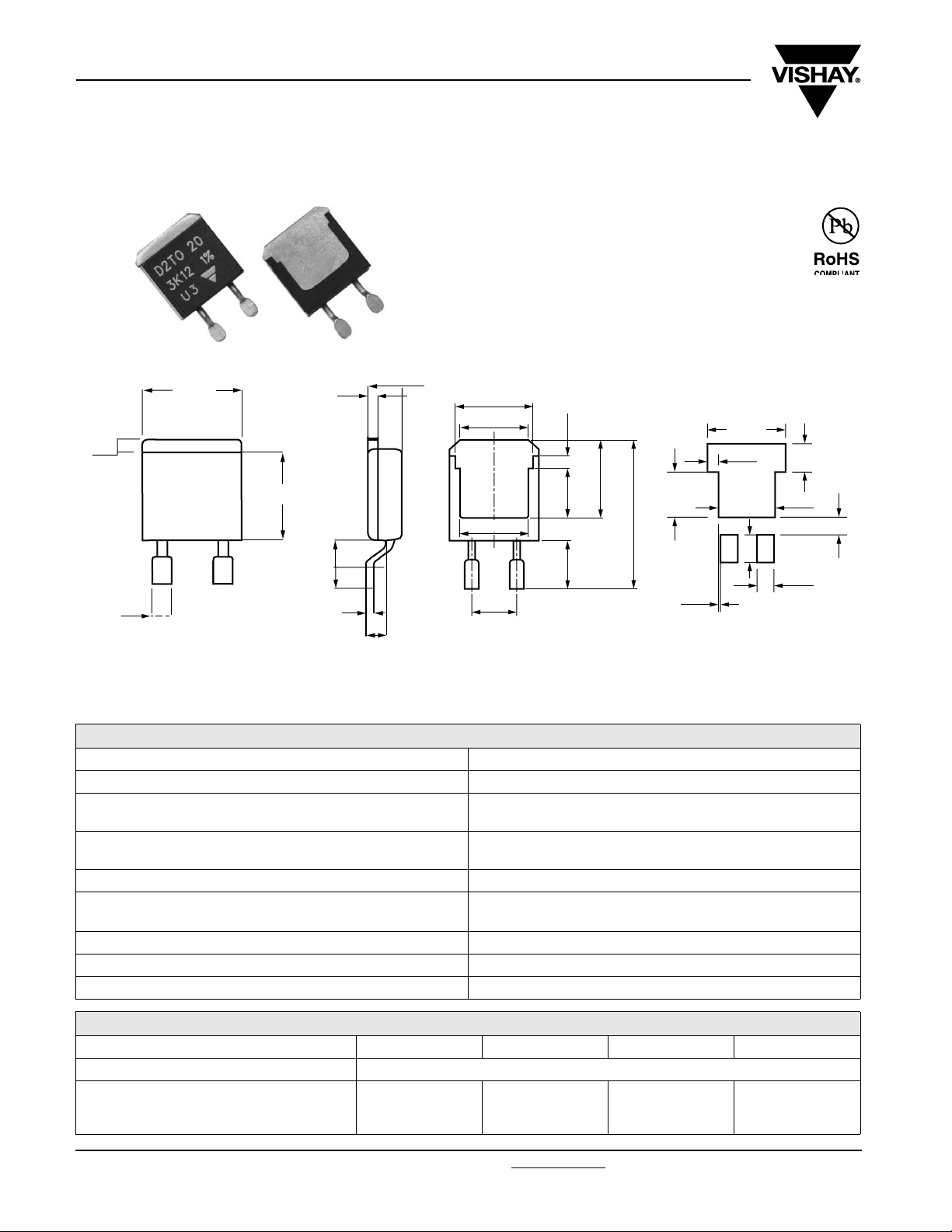
D2TO20
Vishay Sfernice
DIMENSIONS in millimeters
10.1
1.6
1.6
Surface Mounted Power Resistor
Thick Film Technology
FEATURES
• 20 W at 25 °C case temperature
• Surface mounted resistor - TO-263 (D
package
• Wide resistance range from 0.01 Ω to 550 kΩ
• Non Inductive
• RoHS compliant
• Resistor isolated from metal tab
• Solder reflow secure at 270 °C/10 s
8.8
1.25
2
3
0.3
4.5
8.7
7.8 min.
7.6
5.08
Footprint recommendation for
solderable contact area:
8.1
5.15 1.25
15.4
5
6.50
0.26
2
PAK) style
11.00
1.50
4.00
4.02
8.00
2.49
2.40
Tolerance: ± 0.3 mm
Notes
• For the asssembly on board, we recommend the lead (Pb)-free thermal profile as per J-STD-020C
• Power dissipation is 2.8 W at an ambient temperature of 25 °C when mounted on a double sided copper board using FR4 standard, 70 µm of
copper, 39 x 30 x 1.6 mm.
2.5
ELECTRICAL SPECIFICATIONS
Resistance Range 0.01 Ω to 550 kΩ
Tolerances (Standard) ± 1 % to 10 %
Power Rating and Thermal Resistance
Temperature Coefficient
Limiting Element Voltage U
Dielectric Strength IEC 60115-1
Insulation Resistance ≥ 10
Inductance ≤ 0.1 µH
Critical Resistance 3.12 KΩ
L
20 W at 25 °C (case temperature)
R
: 6.5 °C/W
TH (j - c)
See Special Features table
Standard: ± 150 ppm/°C
250 V
2000 V
(between terminals and board)
- 1 min - 10 mA max.
rms
6
MΩ
SPECIAL FEATURES
Resistance Values ≥ 0.010 ≥ 0.045 ≥ 0.1 ≥ 0.5
Tolerances ± 1 % at ± 10 %
Requirement Temperature Coefficient (TCR)
(- 55 °C + 150 °C)
IEC 60115-1
www.vishay.com For technical questions, contact: sfer@vishay.com
36 Revision: 24-Nov-08
± 1100 ppm/°C ± 700 ppm/°C ± 250 ppm/°C ± 150 ppm/°C
Document Number: 51055
Page 3
D2TO20
Surface Mounted Power Resistor
Thick Film Technology
MECHANICAL SPECIFICATIONS
Mechanical Protection Molded
Resistive Element Thick film
Substrate Alumina
Connections Tinned copper
Weight 2.2 g max.
ENVIRONMENTAL SPECIFICATIONS
Temperature Range - 55 °C to 155 °C
IEC 60695-11-5
Flammability
DIMENSIONS
Standard package
2 applications 30 s
separated by 60 s
TO
-263 Style
(D2PAK)
Vishay Sfernice
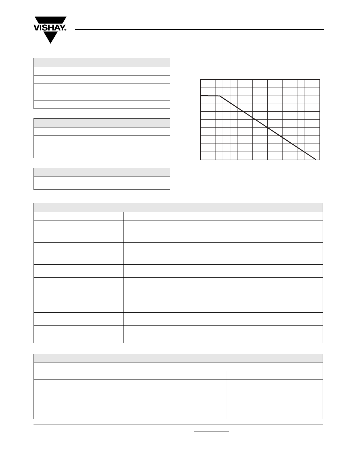
POWER RATING
The temperature of the case should be maintained within the
limits specified.
120
100
75
50
% RATED POWER
25
0
0
40
20
CASE TEMPERATURE IN °C
80
60
100
120
140 155
PERFORMANCE
TESTS CONDITIONS REQUIREMENTS
IEC 60115-1 §4.13
Momentary Overload
Rapid Temperature Change
Load Life
Humidity (Steady State)
Vibration
Terminal Strength
Shock
2 Pr 5 s for R < 2 Ω
1.6 Pr 5 s for R ≥ 2 Ω
Us < 1.5 U
IEC 60115-1
Te s t Na
5 cycles - 1 h
- 55 °C to + 155 °C
IEC 60115-1
1000 h at + 25 °C
IEC 60115-1
IEC60068-2-3
Test Ca: 56 days R.H. 95 %
MIL STD 202
Method 204 - Test. D
10 to 2000 Hz
IEC 60115-1
Test Ua1/Tensile: 20 N/10 s
IEC 60115-1
IEC 60068-2-27
Saw-tooth: 100 gn/6 ms
L
± (0.25 % + 0.005 Ω)
± (0.5 % + 0.005 Ω)
± (1 % + 0.005 Ω)
± (0.5 % + 0.005 Ω)
± (0.2 % + 0.005 Ω)
± (0.2 % + 0.005 Ω)
± (0.5 % + 0.005 Ω)
ASSEMBLY SPECIFICATIONS
For the assembly on board, we recommend the lead (Pb)-free thermal profile as per J-STD-020C
TESTS CONDITIONS REQUIREMENTS
IEC 60115-1
Resistance to Soldering Heat
Solder Bath method: 270 °C/10 s
Moisture Sensitivity Level (MSL)
Document Number: 51055 For technical questions, contact: sfer@vishay.com
Revision: 24-Nov-08 37
IEC 60068-2-58
IPC/JEDEC J-STD-020C
85 °C/85 % RH/168 h
± (0.5 % + 0.005 Ω)
Level: 1
+ Pass requirements of TCR
Overload and Dielectic Strength after MSL
www.vishay.com
Page 4

D2TO20
Vishay Sfernice
Surface Mounted Power Resistor
Thick Film Technology
CHOISE OF THE BOARD
The user must choose the board according to the working conditions of the component (power, room temperature). Maximum
working temperature must not exeed 155 °C. The dissipated power is simply calculated by the following ratio:
TH (j - c)
ΔT
[]+
TH (c - a)
------------------------------------------------------------- --
P
=
[]R
R
P: Expressed in W
ΔT: Difference between maximum working temperature and room temperature
R
: Thermal resistance value measured between resistive layer and outer side of the resistor. It is the thermal
TH (j - c)
resistance of the component: 6.5 °C/W.
R
TH (c - a )
: Thermal resistance value measured between outer side of the resistor and room temperature. It is the thermal
resistance of the solder layer (according the quality of the soldering) and the thermal resistance of the board.
Example:
R
Thermal resistance R
for D2TO20 power rating 2.5 W at ambient temperature + 25 °C.
TH (c - a)
TH (j - c)
: 6.5 °C/W
Considering equation (1) we have:
ΔT = 155 °C - 25 °C = 130 °C
R
TH (j - c)
R
TH (c - a)
+ R
= 52 °C/W - 6.5 °C/W = 45.5 °C/W
= ΔT/P = 130/2.5 = 52 °C/W
TH (c - a)
ACCIDENTAL OVERLOAD
In any case the applied voltage must be lower than the maximum overload voltage of 375 V. The values indicated on the graph
below are applicable to resistors in air or mounted onto a board.
ENER GY CURVE
10
1
ENERGY IN JOULES
0.1
0.01
Single Pulse:
These informations are for a single pulse on a cold resistor at 25 °C (not already used for a dissipation) and for pulses of 100 ms
maximum duration.
The formula used to calculate E is:
with:
E (J): Pulse energy
P (W): Pulse power
t (s): Pulse duration
U (V): Pulse voltage
R (Ω): Resistor
The energy calculated must be less than that allowed by the graph.
10
-6
-5
10
OVERLOAD DURATION IN s
EP x t
10
-4
U
------- x t==
R
-3
10
2
10
-2
www.vishay.com For technical questions, contact: sfer@vishay.com Document Number: 51055
38 Revision: 24-Nov-08
Page 5
D2TO20
Surface Mounted Power Resistor
Vishay Sfernice
Thick Film Technology
Repetitive or Superimposed Pulses:
The following formula is used to calculate the “equivalent“ energy of a repetitive pulse or the “equivalent energy“ of a pulse on a
resistor that is already dissipating power.
P
a
=
16
⎛⎞
------+
⎝⎠
P
r
15.8
) must not exceed the
a
24
EcE x 1
with:
E
(J): Equivalent pulse energy
c
E (J): Known pulse energy
: Resistor power rating
P
r
Pa: Mean power being dissipated
The energy calculated must be less than that allowed by the graph and the average power dissipated (P
continuous power of resistor.
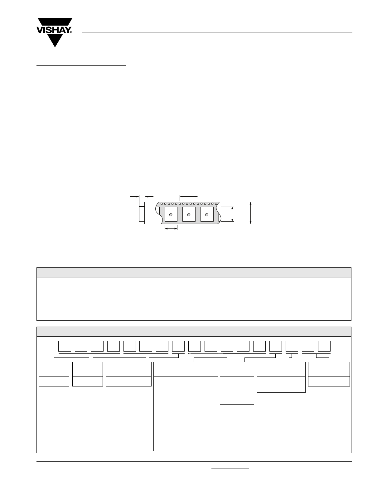
PACKAGING
• Reel
• Tube
• Tape dimensions (mm) for reel:
4.9
10.6
MARKING
Model, Style, Resistance Value (in Ω), Tolerance (in %), Manufacturing Date, Vishay Trademark
ORDERING INFORMATION
D2TO 020 C 100 kΩ ± 1 % XXX e3
MODEL STYLE CONNECTIONS RESISTANCE
VAL UE
TOLERANCE CUSTOM DESIGN LEAD (Pb)-FREE
F = ± 1 %
G = ± 2 %
J = ± 5 %
K = ± 10 %
Optional on request:
shape, etc
SAP PART NUMBERING GUIDELINES
020CR20 0 R 3TD O2 0KE
GLOBAL
MODEL
D2TO 020 C = Surface mount The firts four digits are
SIZE LEADS OHMIC VALUE TOLERANCE PACKAGING LEAD (Pb)-FREE
R = Reel 500 pieces
T = Tube 50 pieces
significant figures and the
last digit specifies the
number of zeros to follow.
R designates decimal point.
48R70 = 48.7 Ω
48701 = 48 700 Ω
10002 = 100 000 Ω
R0100 = 0.01 Ω
R6800 = 0.68 Ω
27000 = 2700 Ω = 2K7 Ω
F = 1 %
G = 2 %
J = 5 %
K = 10 %
E3 = Pure tin
Document Number: 51055 For technical questions, contact: sfer@vishay.com
Revision: 24-Nov-08 39
www.vishay.com
Page 6

Legal Disclaimer Notice
Vishay
Disclaimer
All product specifications and data are subject to change without notice.
Vishay Intertechnology, Inc., its affiliates, agents, and employees, and all persons acting on its or their behalf
(collectively, “Vishay”), disclaim any and all liability for any errors, inaccuracies or incompleteness contained herein
or in any other disclosure relating to any product.
Vishay disclaims any and all liability arising out of the use or application of any product described herein or of any
information provided herein to the maximum extent permitted by law. The product specifications do not expand or
otherwise modify Vishay’s terms and conditions of purchase, including but not limited to the warranty expressed
therein, which apply to these products.
No license, express or implied, by estoppel or otherwise, to any intellectual property rights is granted by this
document or by any conduct of Vishay.
The products shown herein are not designed for use in medical, life-saving, or life-sustaining applications unless
otherwise expressly indicated. Customers using or selling Vishay products not expressly indicated for use in such
applications do so entirely at their own risk and agree to fully indemnify Vishay for any damages arising or resulting
from such use or sale. Please contact authorized Vishay personnel to obtain written terms and conditions regarding
products designed for such applications.
Product names and markings noted herein may be trademarks of their respective owners.
Document Number: 91000 www.vishay.com
Revision: 18-Jul-08 1
 Loading...