

Page 1
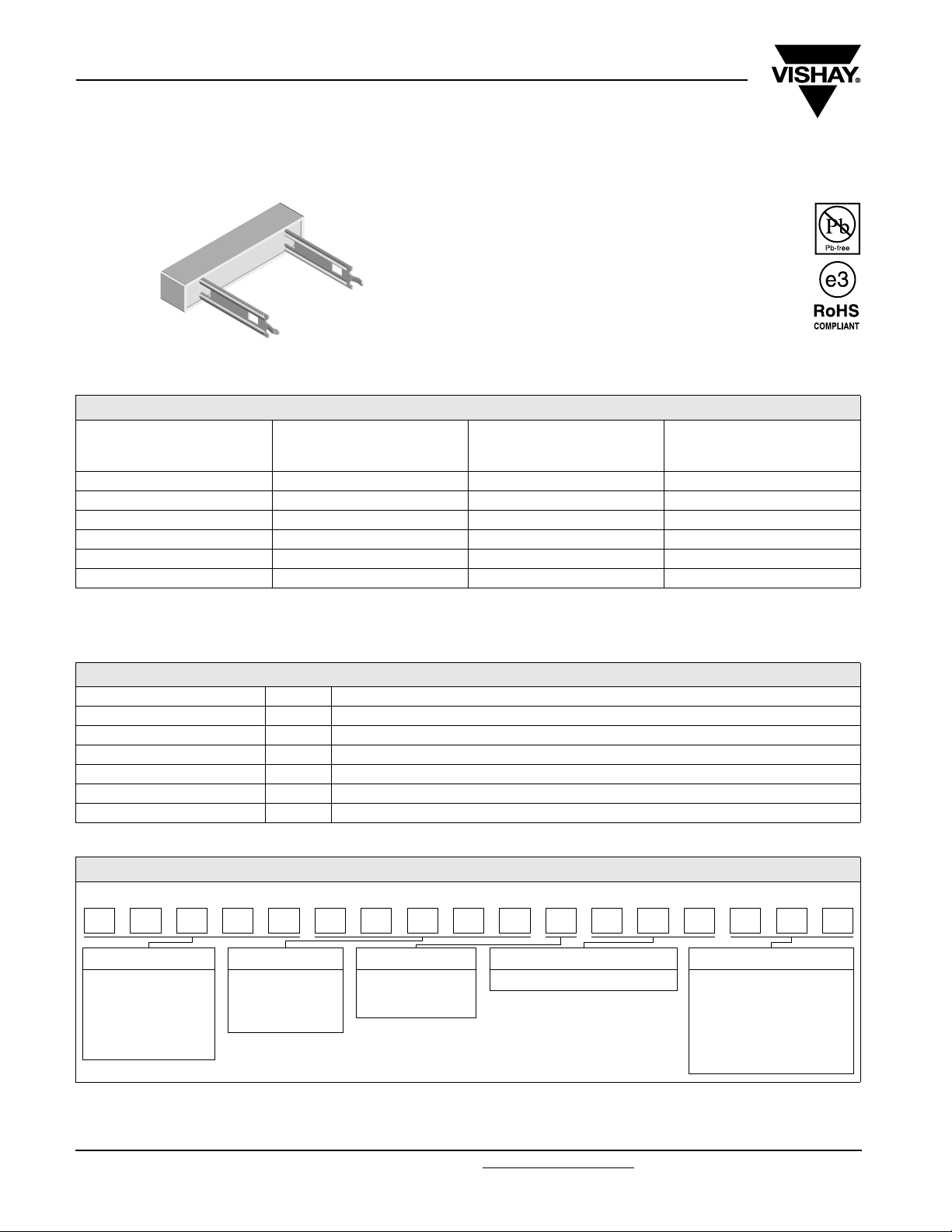
CPR Special Terminals
Vishay Dale
Wirewound Resistors, Commercial Power,
Radial Terminals
FEATURES
• Direct mounting on printed circuit board
• Circuit board lock-in mounting tabs
• High performance for low cost
• Special inorganic potting compound and
ceramic case provide high thermal
conductivity in a fireproof package
STANDARD ELECTRICAL SPECIFICATIONS
GLOBAL
MODEL
CPR03...xx 3 0.1 - 1K 5.6
CPR05...xx 5 0.1 - 3.3K 6.6
CPR07...xx 7 0.1 - 5.7K 9.4
CPR10...xx 10 0.1 - 6.8K 10.0
CPR15...xx 15 0.1 - 6.8K 20.3
CPR20...xx 20 0.15 - 6.8K 25.6
Notes
(1)
(1)
The xx is for the one or two digit “special” number as described in Global Part Number Information section.
POWER RATING
P
40 °C
W
RESISTANCE RANGE
Ω
± 5 %, ± 10 %
WEIGHT
(TYPICAL)
g
TECHNICAL SPECIFICATIONS
PARAMETER UNIT CPR RESISTOR CHARACTERISTICS
Temperature Coefficient ppm/°C ± 600 below 1.0 Ω, ± 300 1.0 Ω and above
Short Time Overload - 10 x rated power for 5 s
Terminal Strength lb 10 minimum
Dielectric Withstanding Voltage V
Maximum Working Voltage V (P x R)
Operating Temperature Range °C - 65 to + 275
AC
1000
1/2
GLOBAL PART NUMBER INFORMATION
Global Part Numbering Example: CPR0515R00JE5126
PR0515R00JE51C 2 6
GLOBAL MODEL VALUE TOLERANCE PACKAGING SPECIAL
CPR03
CPR05
CPR07
CPR10
CPR15
CPR20
R = Decimal
K = Thousand
R1500 = 0.15 Ω
1K500 = 1500 Ω
H = ± 3.0 %
J = ± 5.0 %
K = ± 10.0 %
E51 = Lead (Pb)-free, bulk CPRxx...21 = 10 mm, 2 pin
CPRxx...26 = 25 mm, 2 pin
CPR05...20 = 25 mm, 1 pin
CPR07...13 = 10 mm, 1 pin
CPR10...13 = 10 mm, 1 pin
CPR15...13 = 10 mm, 1 pin
CPR20...3 = 10 mm, 1 pin
www.vishay.com For technical questions, contact: ww2aresistors@vishay.com
1 Revision: 12-Dec-07
Document Number: 30257
Page 2
CPR Special Terminals
Wirewound Resistors, Commercial Power,
Vishay Dale
Radial Terminals
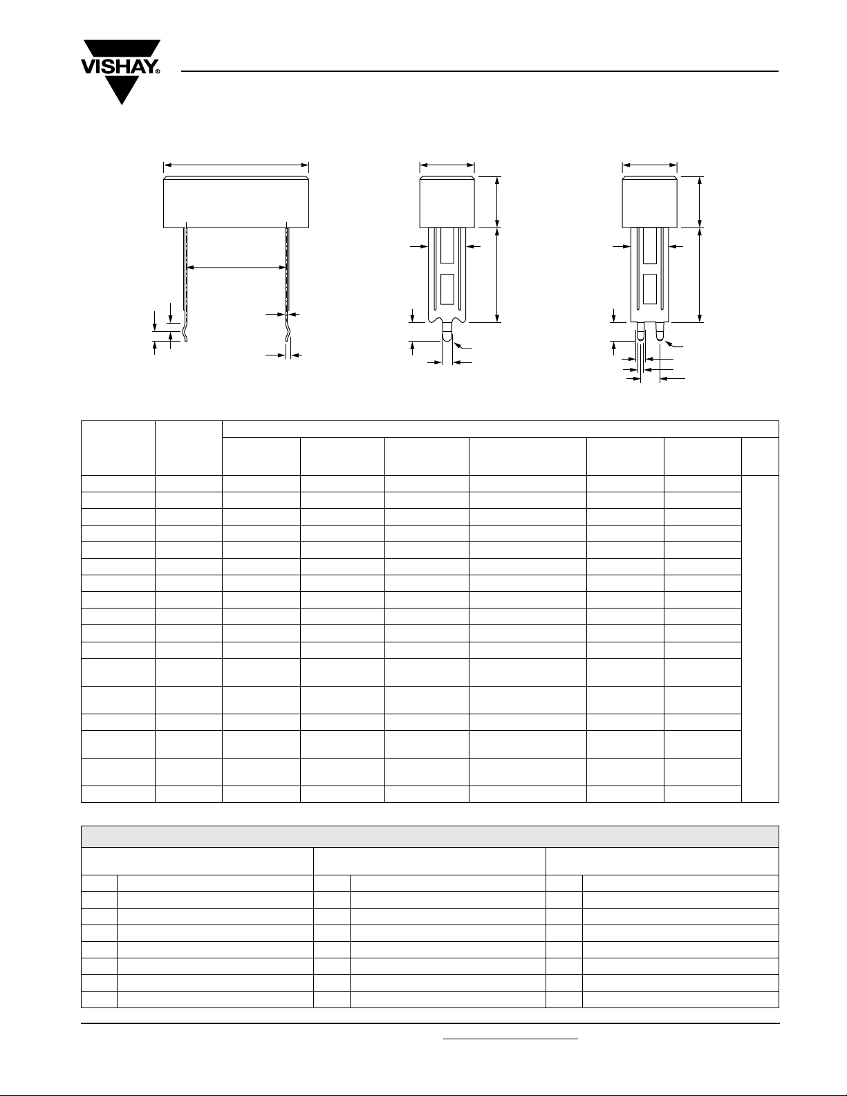
DIMENSIONS in inches [millimeters]
L
P
b
c
GLOBAL
MODEL
CPR03...21 2 0.906 [23.01] 0.375 [9.53] 0.375 [9.53] 0.394 [10.0] 0.197 [5.00] 0.500 [12.70]
CPR03...26 2 0.906 [23.01] 0.375 [9.53] 0.375 [9.53] 0.984 [25.0] 0.197 [5.00] 0.500 [12.70]
CPR05...20 1 1.060 [26.92] 0.375 [9.53] 0.360 [9.14] 0.984 [25.0] - 0.590 [14.99]
CPR05...21 2 1.060 [26.92] 0.375 [9.53] 0.360 [9.14] 0.394 [10.0] 0.197 [5.00] 0.590 [14.99]
CPR05...26 2 1.060 [26.92] 0.375 [9.53] 0.360 [9.14] 0.984 [25.0] 0.197 [5.00] 0.590 [14.99]
CPR07...13 1 1.398 [35.51] 0.375 [9.53] 0.360 [9.14] 0.394 [10.0] - 0.886 [22.50]
CPR07...21 2 1.398 [35.51] 0.375 [9.53] 0.360 [9.14] 0.394 [10.0] 0.197 [5.00] 0.886 [22.50]
CPR07...26 2 1.398 [35.51] 0.375 [9.53] 0.360 [9.14] 0.984 [25.0] 0.197 [5.00] 0.886 [22.50]
CPR10...13 1 1.888 [47.96] 0.375 [9.53] 0.360 [9.14] 0.394 [10.0] - 1.380 [35.05]
CPR10...21 2 1.888 [47.96] 0.375 [9.53] 0.360 [9.14] 0.394 [10.0] 0.197 [5.00] 1.380 [35.05]
CPR10...26 2 1.888 [47.96] 0.375 [9.53] 0.360 [9.14] 0.984 [25.0] 0.197 [5.00] 1.380 [35.05]
CPR15...13 1 1.888 [47.96] 0.500 [12.70] 0.500 [12.70]
CPR15...21 2 1.888 [47.96] 0.500 [12.70] 0.500 [12.70]
CPR15...26 2 1.888 [47.96] 0.500 [12.70] 0.500 [12.70] 1.181 [30.0] 0.197 [5.00] 1.280 [32.51]
CPR20...3 1 2.498 [63.45] 0.500 [12.70] 0.500 [12.70]
CPR20...21 2 2.498 [63.45] 0.500 [12.70] 0.500 [12.70]
CPR20...26 2 2.498 [63.45] 0.500 [12.70] 0.500 [12.70] 1.181 [30.0] 0.197 [5.00] 1.870 [47.50]
TERMINAL
STYLE
± 0.040 [1.02]W ± 0.031 [0.787]H1± 0.031 [0.787]
f
d
TERMINAL STYLE 1
L
W
H1
g
H2
j
(SINGLE PIN)
DIMENSIONS in inches [millimeters]
R
h
H2
+ 0.080 [2.03]
- 0.040 [1.02]
0.394 + 0.080 - 0.130
[10.0 + 2.03 - 3.30]
0.394 + 0.080 - 0.130
[10.0 + 2.03 - 3.30]
0.300 + 0.080 - 0.130
[7.62 + 2.03 - 3.30]
0.300 + 0.080 - 0.130
[7.62 + 2.03 - 3.30]
W
H1
g
H2
j
TERMINAL STYLE 2
(DOUBLE PIN)
D
± 0.005 [0.13]P± 0.060 [1.52]
- 1.280 [32.51]
0.197 [5.00] 1.280 [32.51]
- 1.870 [47.50]
0.197 [5.00] 1.870 [47.50]
R
h
i
D
R
0.03
[0.75]
Ty p.
OTHER DIMENSIONS in inches [millimeters]
CPR05...20, CPRxx...13, CPR20...3
b 0.09 ± 0.01 [2.3 ± 0.25] b 0.06 ± 0.01 [1.5 ± 0.25] b 0.06 ± 0.01 [1.5 ± 0.25]
c 0.09 ± 0.01 [2.3 ± 0.25] c 0.06 ± 0.01 [1.5 ± 0.25] c 0.06 ± 0.01 [1.5 ± 0.25]
d 0.053 ± 0.005 [1.35 ± 0.127] d 0.045 ± 0.005 [1.14 ± 0.127] d 0.045 ± 0.005 [1.14 ± 0.127]
f 0.020 ± 0.001 [0.51 ± 0.025] f 0.020 ± 0.001 [0.50 ± 0.025] f 0.020 ± 0.001 [0.50 ± 0.025]
g 0.287 ± 0.005 [7.30 ± 0.127] g 0.287 ± 0.005 [7.30 ± 0.127] g 0.394 ± 0.005 [10.0 ± 0.127]
h 0.055 ± 0.005 [1.40 ± 0.127] h 0.078 ± 0.005 [2.0 ± 0.127] h 0.078 ± 0.005 [2.0 ± 0.127]
j 0.18 ± 0.01 [4.5 ± 0.25] i 0.059 ± 0.005 [1.50 ± 0.127] i 0.059 ± 0.005 [1.50 ± 0.127]
Document Number: 30257 For technical questions, contact: ww2aresistors@vishay.com
Revision: 12-Dec-07 2
CPRxx...21, CPR03...26, CPR05...26,
CPR07...26, CPR10...26
j 0.197 ± 0.01 [5.0 ± 0.25] j 0.197 ± 0.01 [5.0 ± 0.25]
CPR15...26, CPR20...26
www.vishay.com
Page 3

CPR Special Terminals
Vishay Dale
Wirewound Resistors, Commercial Power,
Radial Terminals
MATERIAL SPECIFICATIONS
Element: Copper-nickel alloy or nickel-chrome alloy,
depending on resistance value
Core: Woven fiberglass
Body: Steatite ceramic case with inorganic potting
compound
Terminals: Tin plated CRS
Part Marking: DALE, model, wattage, value, tolerance,
date code
PERFORMANCE
TEST CONDITIONS OF TEST TEST LIMITS
Thermal Shock - 25 °C to + 155 °C, 5 cycles, 30 min dwell time ± (1.0 % + 0.05 Ω) ΔR
Short Time Overload 10 x rated power for 5 s ± (2.0 % + 0.05 Ω) ΔR
Dielectric Withstanding Voltage 1000 V
Low Temperature Operation - 65 °C, full rated working voltage for 45 min ± (3.0 % + 0.05 Ω) ΔR
Humidity 75 °C, 90 % - 100 % RH, 240 h ± (5.0 % + 0.05 Ω) ΔR
Load Life 1000 h at rated power, + 40 °C, 1.5 h “ON”, 0.5 h “OFF” ± (5.0 % + 0.05 Ω) ΔR
Terminal Strength 10 pounds in axial direction for 30 s ± (2.0 % + 0.05 Ω) ΔR
Resistance to Solder Heat Terminal immersed 3.5 s in molten solder at 1/8" to 3/16" from body ± (1.0 % + 0.05 Ω) ΔR
for 1 min ± (2.0 % + 0.05 Ω) ΔR
rms
120
100
80
60
RATED POWER IN %
40
20
0
- 55 75 275- 25 175
Derating
25
40
125
AMBIENT TEMPERATURE IN °C
225
www.vishay.com For technical questions, contact: ww2aresistors@vishay.com Document Number: 30257
3 Revision: 12-Dec-07
Page 4

Legal Disclaimer Notice
Vishay
Disclaimer
All product specifications and data are subject to change without notice.
Vishay Intertechnology, Inc., its affiliates, agents, and employees, and all persons acting on its or their behalf
(collectively, “Vishay”), disclaim any and all liability for any errors, inaccuracies or incompleteness contained herein
or in any other disclosure relating to any product.
Vishay disclaims any and all liability arising out of the use or application of any product described herein or of any
information provided herein to the maximum extent permitted by law. The product specifications do not expand or
otherwise modify Vishay’s terms and conditions of purchase, including but not limited to the warranty expressed
therein, which apply to these products.
No license, express or implied, by estoppel or otherwise, to any intellectual property rights is granted by this
document or by any conduct of Vishay.
The products shown herein are not designed for use in medical, life-saving, or life-sustaining applications unless
otherwise expressly indicated. Customers using or selling Vishay products not expressly indicated for use in such
applications do so entirely at their own risk and agree to fully indemnify Vishay for any damages arising or resulting
from such use or sale. Please contact authorized Vishay personnel to obtain written terms and conditions regarding
products designed for such applications.
Product names and markings noted herein may be trademarks of their respective owners.
Document Number: 91000 www.vishay.com
Revision: 18-Jul-08 1
 Loading...