

Page 1

6121 Baker Road,
Suite 108
Minnetonka, MN 55345
www.chtechnology.com
Phone (952) 933-6190
Fax (952) 933-6223
1-800-274-4284
Thank you for downloading this document from C&H Technology, Inc.
Please contact the C&H Technology team for the following questions -
Technical
Application
Assembly
Availability
Pricing
Phone – 1-800-274-4284
E-Mail – sales@chtechnology.com
www.chtechnology.com - SPECIALISTS IN POWER ELECTRONIC COMPONENTS AND ASSEMBLIES - www.chtechnology.com
Page 2
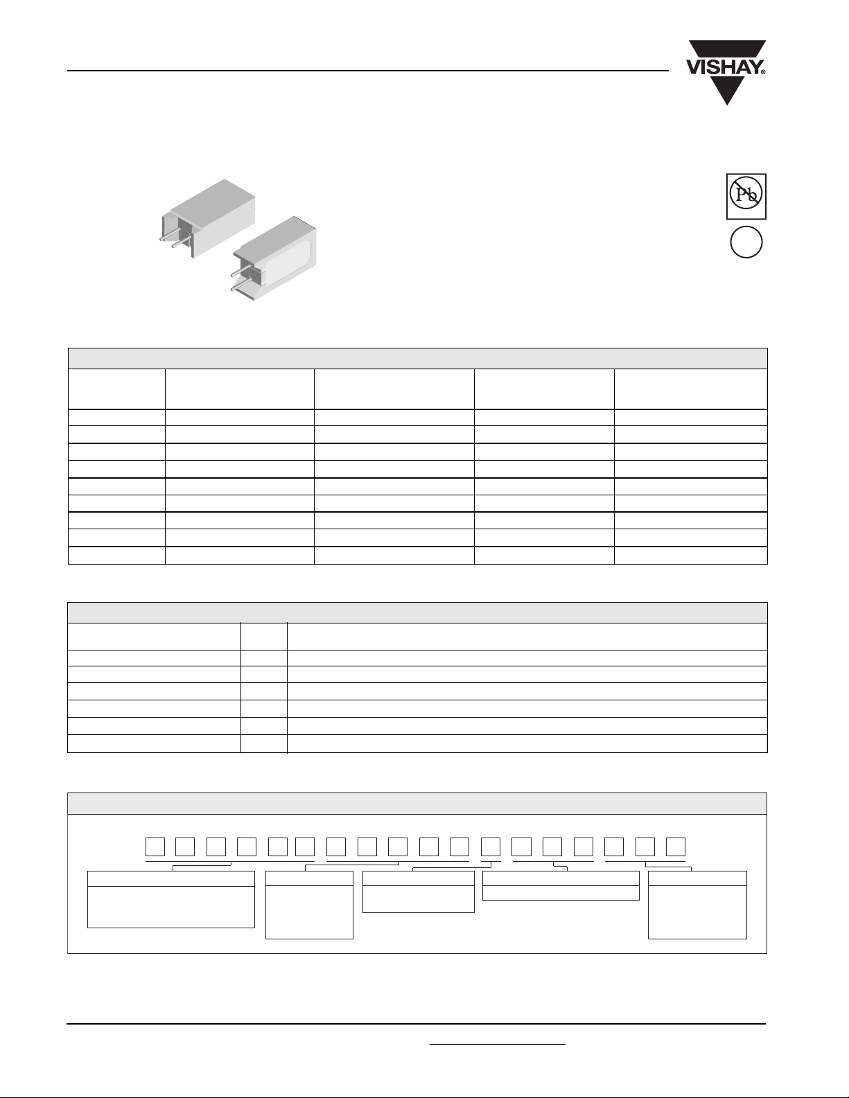
CPCC, CPCF High Volume
Vishay Dale
Wirewound Resistors, Commercial Power,
Vertical Mount
FEATURES
Space saving
•
Direct mounting on printed circuit board
•
High power to size ratio
•
Special cement potting compound and ceramic
•
case provide high thermal conductivity in a fireproof package
STANDARD ELECTRICAL SPECIFICATIONS
POWER RATING RESISTANCE RANGE WEIGHT
GLOBAL P
MODEL W ± 5 %, ± 10 % TECHNOLOGY
CPCC02 2 0.1 - 100 Wirewound 4.7
CPCF02 2 101 - 10 k Metal Oxide 4.7
CPCC03 3 0.1 - 180 Wirewound 5.5
CPCF03 3 181 - 50 k Metal Oxide 5.5
CPCC05 5 0.1 - 180 Wirewound 6.9
CPCF05 5 181 - 50 k Metal Oxide 6.9
CPCC07 7 0.1 - 430 Wirewound 9.2
CPCF07 7 431 - 47 k Metal Oxide 9.2
CPCC10 10 0.1 - 470 Wirewound 14.3
40 °C
Ω (Typical)
Pb-free
e3
RoHS
COMPLIANT
g
TECHNICAL SPECIFICATIONS
PARAMETER UNIT CPCC AND CPCF HIGH VOLUME RESISTOR CHARACTERISTICS
Temperature Coefficient ppm/°C ± 400
Short Time Overload - 5 x rated power for 5 seconds
Maximum Working Voltage V (P x R)
Operating Temperature Range °C - 65/+ 275 for Wirewound, - 65/ + 225 for Metal Oxide
Terminal Strength lb 10 minimum
Dielectric Withstanding Voltage V
AC
1/2
1000
GLOBAL PART NUMBER INFORMATION
Global Part Numbering Example: CPCC0515R00JE66
CPCC0515R00JE66
GLOBAL MODEL VALUE TOLERANCE PACKAGING SPECIAL
(See Standard Electrical R = Decimal J = ± 5.0 % E66 = Lead (Pb)-free, bulk (Dash Number)
Specifications Global Model K = Thousand K = ± 10 % (up to 3 digits)
column for options) R1500 = 0.15 Ω From 1-999 as
1K500 = 1500 Ω applicable
www.vishay.com
48
For technical questions, contact ww2aresistors@vishay.com Document Number 30116
Revision 12-Jan-06
Page 3

CPCC, CPCF High Volume
Wirewound Resistors, Commercial Power, Vertical Mount
DIMENSIONS
H
3.5 ± 1
± 0.040]
LD
CC
W
L
MATERIAL SPECIFICATIONS
Part Marking: DALE, Model, Wattage, Value, Tolerance,
Date Code
CPCC: Element: Copper-nickel alloy or nickel-chrome alloy,
depending on resistance value
Core: Woven fiberglass
Body: Steatite ceramic case with cement potting compound
End Caps: Tin plated steel
Terminals: Tinned copper
CPCF: Element: Metal film - nickel-chrome alloy
Core: Alumina ceramic
Body: Steatite ceramic case with inorganic potting compound
End Caps: Brass alloy
Terminals: Tinned copper
[0.138
Vishay Dale
DIMENSIONS in millimeters [inches]
GLOBAL
MODEL [0.060] [0.040] [0.040] [0.002] [+ 0.08 - 0.04]
CPCC02 20 11 3.5 0.8 5
CPCF02 20 11 3.5 0.8 5
CPCC03 25 12 8 0.8 5
CPCF03 25 12 8 0.8 5
CPCC05 25 13 9 0.8 5
CPCF05 25 13 9 0.8 5
CPCC07 39 13 9 0.8 5
CPCF07 39 13 9 0.8 5
CPCC10 35 16 12 0.8 7.5
HWLLD CC
± 1.5 ± 1.0 ± 1.0 ± 0.05 + 2 - 1
[0.787] [0.433] [0.138] [0.031] [0.197]
[0.787] [0.433] [0.138] [0.031] [0.197]
[0.984] [0.472] [0.315] [0.031] [0.197]
[0.984] [0.472] [0.315] [0.031] [0.197]
[0.984] [0.512] [0.354] [0.031] [0.197]
[0.984] [0.512] [0.354] [0.031] [0.197]
[1.535] [0.512] [0.354] [0.031] [0.197]
[1.535] [0.512] [0.354] [0.031] [0.197]
[1.378] [0.630] [0.472] [0.031] [0.295]
120
100
80
60
RATED POWER IN %
40
20
0
- 65 - 25 25 75 125 175 225 275
Derating
Metal Oxide
40
AMBIENT TEMPERATURE IN
Wirewound
°C
PERFORMANCE
TEST CONDITIONS OF TEST CPCC, CPCF
Thermal Shock
Short Time Overload 5 x rated power for 5 seconds ± (4.0 % + 0.05 Ω) ∆R
Dielectric Withstanding Voltage 1000 V
Low Temperature Operation - 65 °C, full rated working voltage for 45 minutes ± (3.0 % + 0.05 Ω) ∆R
Bias Humidity 75 °C, 90 % - 100 % RH, 240 hours ± (5.0 % + 0.05 Ω) ∆R
Load Life 1000 hours at rated power, + 25 °C, 1.5 hours “ON”, 0.5 hours “OFF” ± (10.0 % + 0.05 Ω) ∆R
Terminal Strength 5 to 10 second 10 pound pull test ± (2.0 % + 0.05 Ω) ∆R
Resistance to Solder Heat Terminal immersed 3.5 seconds in molten solder up to body ± (4.0 % + 0.05 Ω) ∆R
Revision 12-Jan-06
- 55 °C to + 275 °C (+ 225 °C for Metal Oxide), 5 cycles, 30 minute dwell time
for one minute ± (2.0 % + 0.05 Ω) ∆R
rms
For technical questions, contact ww2aresistors@vishay.comDocument Number 30116
TEST LIMITS
± (5.0 % + 0.05 Ω) ∆R
www.vishay.com
49
 Loading...