

Page 1

6121 Baker Road,
Suite 108
Minnetonka, MN 55345
www.chtechnology.com
Phone (952) 933-6190
Fax (952) 933-6223
1-800-274-4284
Thank you for downloading this document from C&H Technology, Inc.
Please contact the C&H Technology team for the following questions -
Technical
Application
Assembly
Availability
Pricing
Phone – 1-800-274-4284
E-Mail – sales@chtechnology.com
www.chtechnology.com - SPECIALISTS IN POWER ELECTRONIC COMPONENTS AND ASSEMBLIES - www.chtechnology.com
Page 2

Dimension Inches Millimeters
A 3.681 Max. 93.5 Max.
B 3.150 80
C 1.181 Max. 30 Max.
D 1.024 Max. 26 Max.
E 0.906 23
F 0.827 21
G 0.650 16.5
H 0.512 13
J 0.354 9
K 0.256 6.5
L 0.256 Dia. Dia. 6.5
M M5 Metric M5
Description:
Powerex Dual SCR
POW-R-BLOK™ Modules are
designed for use in applications
requiring phase control and
isolated packaging.The modules
are isolated for easy mounting
with other components on
common heatsinks.
Features:
M Isolated Mounting
M Glass Passivated Chips
M Metal Baseplate
M Low Thermal Impedance
Applications:
M Battery Supplies
M Bridge Circuits
M AC and DC Motor Control
M Tap Changers
M Lighting Control
Ordering Information:
Select the complete eight digit
module part number you desire
from the table below.
Example: CM4312A2 is a
1200 Volt, 25 Ampere Dual SCR
POW-R-BLOK™ Module.
Voltage Current Rating
Type Volts (x100) Amperes (25)
CM43 12 A2
16
S-13
Powerex,Inc., 200 Hillis Street,Youngwood,Pennsylvania 15697-1800 (724) 925-7272
Dual SCR
POW-R-BLOK™ Modules
25 Amperes/1200-1600 Volts
CM4312A2
CM4316A2
Outline Drawing
CM4312A2, CM4316A2
Dual SCR POW-R-BLOK™ Modules
25 Amperes/1200-1600 Volts
A
B
L - DIA.
(2 TYP.)
C
K
A1K2
A1K2 K1 A2
E
G
K1
K2 G2
D
H
K1 G1
E
M - M5 THD
(3 TYP.)
.110 T AB
J
F
A2
K2 G2
K1
G1
Page 3

S-14
Powerex,Inc., 200 Hillis Street,Youngwood,Pennsylvania 15697-1800 (724) 925-7272
CM4312A2, CM4316A2
Dual SCR POW-R-BLOK™ Modules
25 Amperes/1200-1600 Volts
Absolute Maximum Ratings
Characteristics Symbol CM4312A2 CM4316A2 Units
Peak Forward Blocking Voltage V
DRM
1200 1600 Volts
Transient Peak Forward Blocking Voltage (Non-Repetitive), t < 5ms V
DSM
1350 1700 Volts
DC Forward Blocking Voltage V
D(DC)
960 1280 Volts
Peak Reverse Blocking Voltage V
RRM
1200 1600 Volts
Transient Peak Reverse Blocking Voltage (Non-Repetitive), t < 5ms V
RSM
1350 1700 Volts
DC Reverse Blocking Voltage V
R(DC)
960 1280 Volts
RMS On-State Current I
T(RMS)
39 39 Amperes
Average On-State Current, TC= 86°C I
T(AV)
25 25 Amperes
Peak One-Cycle Surge (Non-Repetitive) On-State Current (60Hz) I
TSM
490 490 Amperes
Peak One-Cycle Surge (Non-Repetitive) On-State Current (50Hz) I
TSM
445 445 Amperes
I2t (for Fusing), 8.3 milliseconds I2t 1000 1000 A2sec
Critical Rate-of-Rise of On-State Current* di/dt 100 100 Amperes/ms
Peak Gate Power Dissipation P
GM
5.0 5.0 Watts
Average Gate Power Dissipation P
G(AV)
0.5 0.5 Watts
Peak Forward Gate Voltage V
GFM
10 10 Volts
Peak Reverse Gate Voltage V
GRM
5.0 5.0 Volts
Peak Forward Gate Current I
GFM
2.0 2.0 Amperes
Storage Temperature T
STG
-40 to 125 -40 to 125 °C
Operating Temperature T
j
-40 to 125 -40 to 125 °C
Maximum Mounting Torque M6 Mounting Screw — 26 26 in.-lb.
Maximum Mounting Torque M5 Terminal Screw — 17 17 in.-lb.
Module Weight (Typical) — 160 160 Grams
V Isolation V
RMS
2500 2500 Volts
*Tj= 125°C, IG= 0.5A, VD= 1/2 V
DRM
Page 4

S-15
Powerex,Inc., 200 Hillis Street,Youngwood,Pennsylvania 15697-1800 (724) 925-7272
CM4312A2, CM4316A2
Dual SCR POW-R-BLOK™ Modules
25 Amperes/1200-1600 Volts
Electrical and Thermal Characteristics, Tj= 25°C unless otherwise specified
Characteristics Symbol Test Conditions CM4312A2/CM4316A2 Units
Blocking State Maximums
Forward Leakage Current, Peak I
DRM
Tj= 125°C, V
DRM
= Rated 10 mA
Reverse Leakage Current, Peak I
RRM
Tj= 125°C, V
RRM
= Rated 10 mA
Conducting State Maximums
Peak On-State Voltage V
TM
ITM= 75A 1.8 Volts
Switching Minimums
Critical Rate-of-Rise of Off-State Voltage dv/dt Tj= 125°C, VD= 2/3 V
DRM
500 Volts/ms
Thermal Maximums
Thermal Resistance, Junction-to-Case R
u(J-C)
Per Module 0.8 °C/Watt
Thermal Resistance, Case-to-Sink (Lubricated) R
u(C-S)
Per Module 0.2 °C/Watt
Gate Parameters Maximums
Gate Current-to-Trigger I
GT
VD= 6V, RL= 2Ω 50 mA
Gate Voltage-to-Trigger V
GT
VD= 6V, RL= 2Ω 3.0 Volts
Non-Trigger ing Gate Voltage V
GDM
Tj= 125°C, VD= 1/2 V
DRM
0.25 Volts
Page 5
S-16
Powerex,Inc., 200 Hillis Street,Youngwood,Pennsylvania 15697-1800 (724) 925-7272
CM4312A2, CM4316A2
Dual SCR POW-R-BLOK™ Modules
25 Amperes/1200-1600 Volts
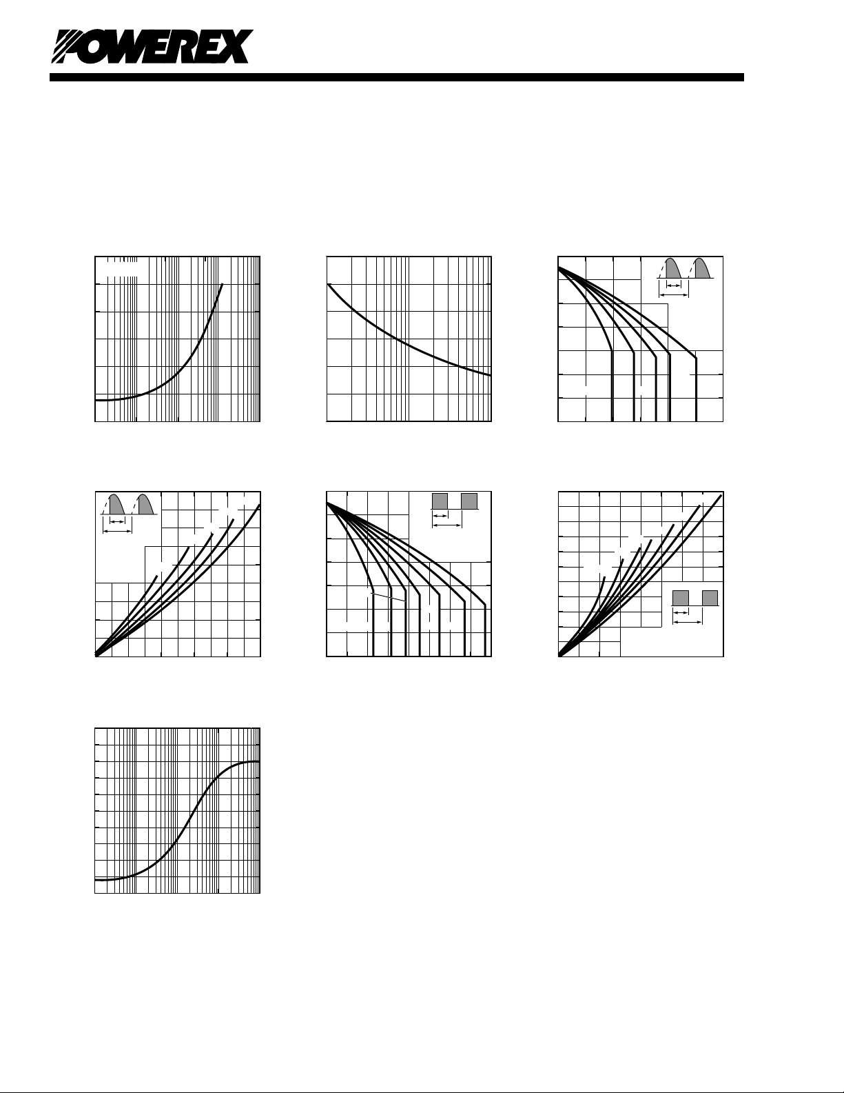
INSTANTANEOUS ON-STATE CURRENT, ITM,
(AMPERES)
MAXIMUM
ON-STATE CHARACTERISTICS
0.5
10
0
1.5
2.0
2.5
3.0
3.5
10
1
10
2
10
3
INSTANTANEOUS ON-STATE VOLTAGE, V
TM
, (VOLTS)
1.0
Tj = 125oC
10
4
CYCLES AT 60 HZ
MAXIMUM PEAK SURGE (NON-REPETITIVE)
CURRENT, I
TSM
, (AMPERES)
MAXIMUM ALLOWABLE PEAK SURGE
(NON-REPETITIVE) CURRENT
0
10
1
10
2
10
0
600
500
400
300
200
100
MAXIMUM ALLOWABLE CASE TEMPERATURE
(SINUSOIDAL WAVEFORM)
AVERAGE ON-STATE CURRENT, I
T(AV)
,
(AMPERES)
MAXIMUM ALLOWABLE CASE TEMPERATURE, T
C
, (
o
C)
05 3010 15 20
130
60
o
360
o
u
RESISTIVE,
INDUCTIVE
LOAD PER
SINGLE
ELEMENT
180
o
120
110
100
90
80
70
60
u = 30
o
90
o
120
o
25
MAXIMUM ON-STATE POWER DISSIPATION
(SINUSOIDAL WAVEFORM)
AVERAGE ON-STATE CURRENT, I
T(AV)
,
(AMPERES)
MAXIMUM POWER DISSIPATION, P
AV(MAX)
, (WATTS)
05 2510 15 20
0
45
360
o
u
RESISTIVE,
INDUCTIVE
LOAD PER
SINGLE
ELEMENT
60
o
90
o
5
10
15
20
25
30
35
40
u = 30
o
120
o
180
o
MAXIMUM ALLOWABLE CASE TEMPERATURE
(RECTANGULAR WAVEFORM)
AVERAGE ON-STATE CURRENT, I
T(AV)
,
(AMPERES)
MAXIMUM ALLOWABLE CASE TEMPERATURE, T
C
, (
o
C)
05 2510 15 20 30 35 40
60
70
80
90
100
110
120
130
360
o
u
RESISTIVE, INDUCTIVE
LOAD PER SINGLE
ELEMENT
DC60
o
u = 30
o
90
o
180o270
o
120
o
0
MAXIMUM AVERAGE ON-STATE POWER
DISSIPATION (RECTANGULAR WAVEFORM)
AVERAGE ON-STATE CURRENT, I
T(AV)
,
(AMPERES)
MAXIMUM POWER DISSIPATION, P
AV(MAX)
, (WATTS)
05 2510 15 20 30 35 40
360
o
u
RESISTIVE, INDUCTIVE LOAD
PER SINGLE ELEMENT
55
50
45
40
35
30
25
20
15
10
5
120
o
180
o
270
o
60
o
90
o
DC
u = 30
o
TIME, t, (SECONDS)
TRANSIENT THERMAL IMPEDANCE
CHARACTERISTICS (JUNCTION-TO-CASE)
0
10
-3
0.2
0.4
0.6
0.8
1.0
10
-1
10
0
10
1
TRANSIENT THERMAL IMPEDANCE, Z
u(J-C)
(t), (
o
C/WATT)
10
-2
 Loading...