

Page 1

6121 Baker Road,
Suite 108
Minnetonka, MN 55345
www.chtechnology.com
Phone (952) 933-6190
Fax (952) 933-6223
1-800-274-4284
Thank you for downloading this document from C&H Technology, Inc.
Please contact the C&H Technology team for the following questions -
Technical
Application
Assembly
Availability
Pricing
Phone – 1-800-274-4284
E-Mail – sales@chtechnology.com
www.chtechnology.com - SPECIALISTS IN POWER ELECTRONIC COMPONENTS AND ASSEMBLIES - www.chtechnology.com
Page 2
Powerex, Inc., Hillis Street, Youngwood, Pennsylvania 15697 (724) 925-7272
www.pwrx.com
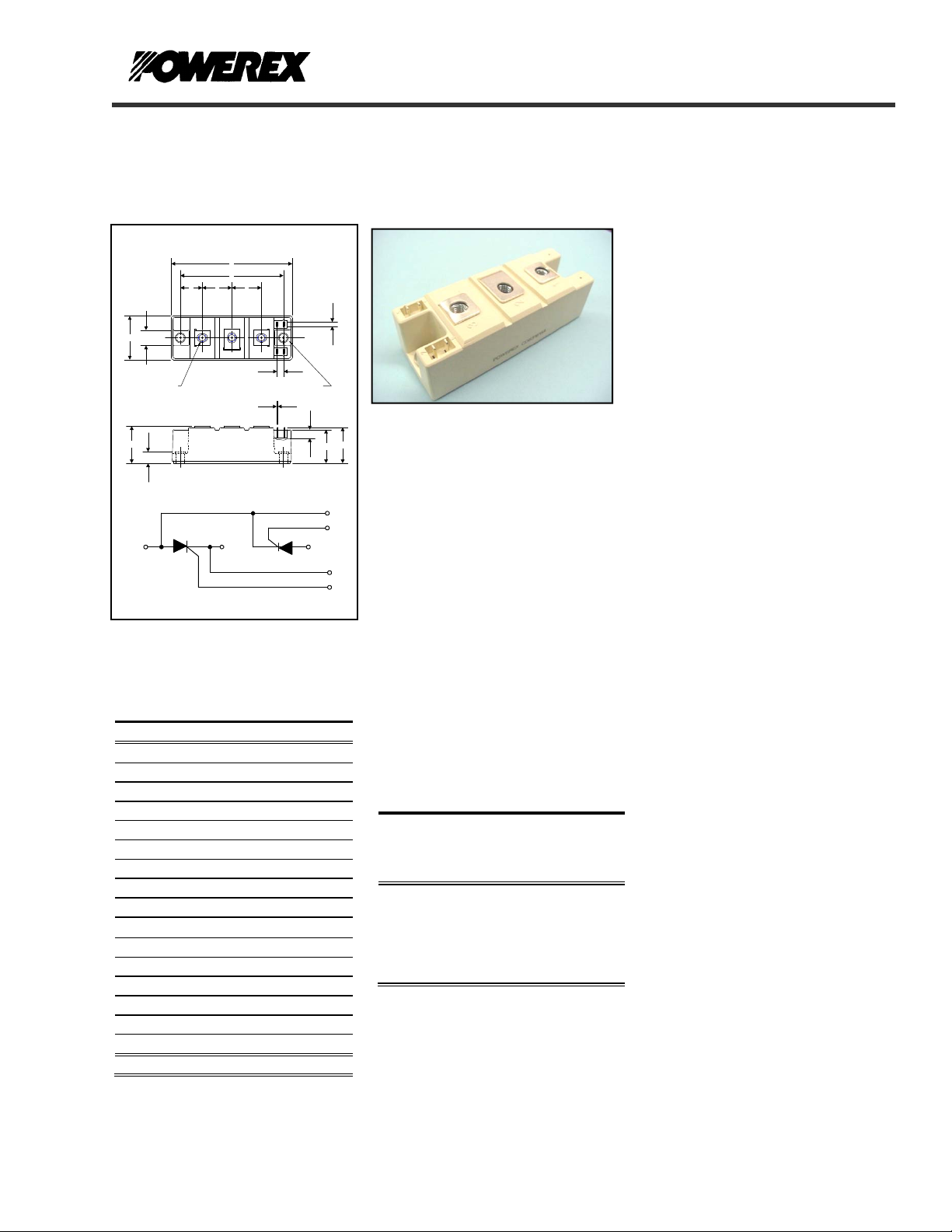
Dual SCR Isolated Module
CD63__15B
POW-R-BLOK
TM
150 Amperes / Up to 1800 Volts
OUTLINE DRAWING
A
D
F F
E
6
7
G
B
12
"J" (3)
C
H
1
~
CONNECTION DIAGRAM
CD63_15B Outline Dimensions
Dimension Inches Millimeters
A 3.70 94
B 1.34 34
C 1.18 30
D 3.15 80
E 0.67 17
F 0.91 23
G 0.51 13
H 0.35 8.3
J M6 M6
K 0.26 6.4
M .020 5
N 0.28 6
P 1.06 27
Q 1.14 29
R 0.03 0.8
S 0.11 2.8
Note: Dimensions are for reference only.
3
4
R
2
+
S
5
M
Ε "K" (2)
N
P
7
6
3
-
Q
CD63__15B
Dual SCR Isolated
POW-R-BLOKTM Module
150 Amperes / Up to 1800 Volts
5
4
Ordering Information:
Select the complete nine digit module
part number from the table below.
Example: CD631615B is a 1600Volt,
150 Ampere Dual SCR Isolated
POW-R-BLOK
TM
Module
Voltage
Type
CD63 08
Volts
(x100)
12
14
16
18
Current
Amperes
(x 10)
15 B
Version
Description:
Powerex Dual SCR Modules are
designed for use in applications
requiring phase control and isolated
packaging. The modules are isolated
for easy mounting with other
components on a common heatsink.
POW-R-BLOK
recognized by the Underwriters
Laboratories.
TM
has been tested and
Features:
Electrically Isolated Heatsinking
DBC Alumina (Al
Glass Passivated Chips
Metal Baseplate
Low Thermal Impedance
for Improved Current Capability
Quick Connect Gate Terminal
with Provision for Keyed Mating
Plug
UL Recognized (E78240)
) Insulator
2O3
Benefits:
No Additional Insulation
Components Required
Easy Installation
No Clamping Components
Required
Reduce Engineering Time
Applications:
Bridge Circuits
AC & DC Motor Drives
Battery Supplies
Power Supplies
Large IGBT Circuit Front Ends
Lighting Control
Heat & Temperature Control
Welders
Revision Date: 04/28/2009
Page 3

A
A
Powerex, Inc., Hillis Street, Youngwood, Pennsylvania 15697 (724) 925-7272 POW-R-BLOK
CD63__15B
TM
www.pwrx.com Dual SCR Isolated Module
150 Amperes / Up to 1800 Volts
Absolute Maximum Ratings
Characteristics Conditions Symbol Units
& V
Repetitive Peak Forward and Reverse Blocking
V
DRM
Voltage
Non-Repetitive Peak Reverse Blocking Voltage
V
(t < 5 msec)
RMS Forward Current
180° Conduction, T
=85°C I
C
verage Forward Current 180° Conduction, TC=82°C
=85°C
C
reapplied, Tj=125°C
reapplied, Tj=125°C
reapplied, Tj=125°C
reapplied, Tj=125°C
reapplied, Tj=125°C
reapplied, Tj=125°C
reapplied, Tj=125°C
reapplied, Tj=125°C
=400A ,
= 125°C
j
P
V
Peak One Cycle Surge Current, Non-Repetitive
Peak Three Cycle Surge Current, Non-Repetitive
Peak Ten Cycle Surge Current, Non-Repetitive
I2t for Fusing for One Cycle
Maximum Rate-of-Rise of On-State Current,
Non Repetitive
Peak Gate Power Dissipation
verage Gate Power Dissipation
Peak Forward Gate Current
Peak Reverse Gate Voltage
180° Conduction, T
60 Hz, 100% V
60 Hz, No V
50 Hz, 100% V
50 Hz, No V
60 Hz, 100% V
50 Hz, 100% V
60 Hz, 100% V
50 Hz, 100% V
8.3 ms, 100% V
8.3 ms, No V
10 ms, 100% V
10 ms, No V
V
D
=0.5 A, Tr < 0.25µs, tp > 6µs
I
G
RRM
reapplied, Tj=125°C
RRM
RRM
reapplied, Tj=125°C
RRM
RRM
RRM
RRM
RRM
RRM
reapplied, Tj=125°C
RRM
RRM
reapplied, Tj=125°C
RRM
=125°C,
T
j
= V
DRM (Rated), ITM
T
< 5 ms, Tj = 125°C
p
F = 50 Hz, T
T
< 5 ms, Tj = 125°C
p
T
< 5 ms, Tj = 125°C
p
Operating Temperature TJ -40 to +125 °C
Storage Temperature T
Max. Mounting Torque, M6 Mounting Screw on
Terminals
Max. Mounting Torque, Module to Heatsink
Module Weight, Typical 165 g
0.36 oz.
V Isolation Tj= 25°C, 1 second
Tj= 25°C, 1 minute
up to 1800 V
RRM
V
RSM
235 A
T(RMS)
I
T(AV)
I
T(AV)
I
TSM
I
TSM
I
TSM
I
TSM
I
TSM
I
TSM
I
TSM
I
TSM
2
I
t
2
I
t
2
t
I
2
t
I
+ 100 V
RRM
160
150
3700
5250
3520
5000
2970
2830
2335
2220
57,040
114,840
61,950
125,000
A
A
A
A
A
A
A
A
A
A
2
A
sec
2
A
sec
2
sec
A
2
sec
A
di/dt 200 A/µs
12 W
P
GM
3 W
G(AV)
3 A
I
GFM
10 V
GRM
-40 to +125 °C
stg
35 - 50
4 - 6
35 - 50
4 - 6
V
rms
V
rms
3600
3000
in.-Lb.
Nm
in.-Lb.
Nm
V
V
Revision Date: 04/28/2009
Page 4

Powerex, Inc., Hillis Street, Youngwood, Pennsylvania 15697 (724) 925-7272 POW-R-BLOK
CD63__15B
TM
www.pwrx.com Dual SCR Isolated Module
150 Amperes / Up to 1800 Volts
Electrical Characteristics, TJ=25°C unless otherwise specified
Characteristics Symbol Test Conditions Min.
Repetitive Peak Forward Leakage Current I
Repetitive Peak Reverse Leakage Current I
Peak On-State Voltage VTM I
Threshold Voltage, Low-level
Slope Resistance, Low-level
Minimum dV/dt dV/dt
Turn-Off Time (Typical) t
Up to 1800V, TJ=125°C 50 mA
DRM
Up to 1800V, TJ=125°C 50 mA
RRM
=500A 1.6 V
TM
V
(TO)1
r
T1
off
= 125°C, I = 16.7% x πI
T
J
Exponential to 2/3 V
=125°C, Gate Open
T
j
T
= 125°C, IT= 300A, Rgk = 100Ω
J
V
= 50V, -dI/dt=15 A/µs
r
T(AV)
DRM
to πI
T(AV)
1000 V/µs
50 - 200 (Typical) µs
Max.
Re-Applied dV/dt = 20V/µs,
Gate Trigger Current IGT
Gate Trigger Voltage VGT
Non-Triggering Gate Voltage V
Non-Triggering Gate Current I
T
GDM
T
GDM
Holding Current IH T
Latching Current IL T
T
= 25°C, VD=6V, Ra=1Ω, Resistive Load
j
T
= 25°C, VD=6V, Ra=1Ω, Resistive Load
j
=125°C, VD=V
j
=125°C, VD=V
j
=25°C 150 (Typical) mA
J
=25°C 300 (Typical) mA
J
Linear to 2/3 V
DRM
150 mA
2.0 Volts
0.25 Volts
DRM
10 mA
DRM
0.85
1.5
Units
V
mΩ
Thermal Characteristics
Characteristics Symbol
Thermal Resistance, Junction to Case
DC Operation
Thermal Resistance, Case to Sink Lubricated
R
R
ΘJ-C
ΘC-S
Per Module, both conducting
Per Junction, both conducting
Max.
Per Module 0.05 °C/W
Information presented is based upon manufacturers testing and projected capabilities.
This information is subject to change without notice.
The manufacturer makes no claim as to the suitability of use, reliability, capability,
or future availability of this product.
0.085
0.17
Revision Date: 04/28/2009
Units
°C/W
°C/W
Page 5

Powerex, Inc., Hillis Street, Youngwood, Pennsylvania 15697 (724) 925-7272 POW-R-BLOK
CD63__15B
TM
www.pwrx.com Dual SCR Isolated Module
150 Amperes / Up to 1800 Volts
5
4
3
2
1
On-State Voltage - Vtm - Volts
0
10 100 1000 10000
250
200
150
100
50
Maximum Power Dissipation Per SCR - Watts
0
0 20 40 60 80 100 120 140 160
300
250
200
150
100
50
Maximum Power Dissipation Per SCR - Watts
0
0 20 40 60 80 100 120 140 160 180 200 220 240 260
Maximum On-State Forward Voltage Drop
Instantaneous On-State Current - Itm - Amperes
Maximum On-State Power Dissipation
Maximum On-State Power Dissipation
30°
15°
Average On-State Current - It(av) - Amperes
( Tj = 125 °C )
(Sinusoidal Waveform)
90°
90°
60°
120°
0
CONDUCTION ANGLE
180°
180
0
CONDUCTION ANGLE
30°
15°
Average On-State Current - It(av) - Amperes
(Rectangular Waveform)
60°
120°
180
270°
360
360
180°
360°
Maximum Transient Thermal Impedance
0.18
0.16
0.14
0.12
0.1
0.08
0.06
0.04
Thermal Impedance - Rjc - °C/W
0.02
0
0.01 0.1 1 10
Maximum Allowable Case Temperature
125
120
115
110
105
100
95
90
Max. Case Temperature - Tcase - °C
85
80
0 20 40 60 80 100 120 140 160
Maximum Allowable Case Temperature
125
120
115
110
105
100
95
90
85
80
Max. Case Temperature - Tcase - °C
75
70
0 20 40 60 80 100 120 140 160 180 200 220 240 260
15°
(Junction to Case)
Time - t - Seconds
(Sinusoidal Waveform)
180
0
60°
120°
CONDUCTION ANGLE
90°
180
0
CONDUCTION ANGLE
180°
15°
30°
Average On-State Current - It(av) - Amperes
(Rectangular Waveform)
30°
60°
90°
Average On-State Current - It(av) - Amperes
120°
270°
Revision Date: 04/28/2009
360
180°
360
360°
 Loading...