

Page 1
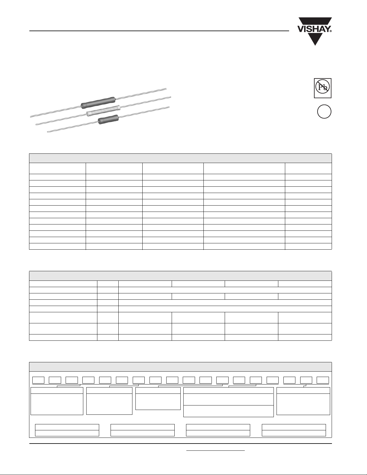
CA
Vishay Dale
Wirewound Resistors, Commercial Power, Axial Lead
FEATURES
• High performance for low cost
• Auto insertable
• CA0001, CA0002 and CA5000 models are
supplied with a high temperature silicone
coating for additional environmental protection
• Lead forming available
APPLICATIONS
Kitchen appliances: Percolators, blenders,
mixers, ranges, toasters, deep fryers. Automotive
devices: Horns, ignitions, windshield wipers,
voltage regulators, instrument gauges. Entertainment
devices: Radios, televisions, computers and power supplies.
STANDARD ELECTRICAL SPECIFICATIONS
GLOBAL
MODEL
CA0001 CA-1 1.0 0.1 - 1K 0.65
CA0002 CA-2 2.0 0.1 - 2.4K 0.80
CA4050/CA5050 CA-4050/CA-5050 2.0/2.5 0.1 - 170/0.1 - 2.7K 0.64/0.78
CA4055/CA5055 CA-4055/CA-5055 2.2/2.75 0.1 - 195/0.1 - 3.1K 0.65/0.80
CA4060/CA5060 CA-4060/CA-5060 2.4/3.0 0.1 - 220/0.1 - 3.5K 0.66/0.82
CA4070/CA5070 CA-4070/CA-5070 2.8/3.5 0.1 - 270/0.1 - 4.3K 0.68/0.86
CA4080/CA5080 CA-4080/CA-5080 3.2/4.0 0.1 - 320/0.1 - 5.1K 0.70/0.90
CA4090/CA5090 CA-4090/CA-5090 3.6/4.5 0.1 - 370/0.1 - 5.9K 0.72/0.94
CA4100/CA5100 CA-4100/CA-5100 4.0/5.0 0.15 - 420/0.15 - 6.7K 0.74/0.98
CA4150/CA5150 CA-4150/CA-5150 6.0/7.5 0.2 - 630/0.2 - 7K 0.84/1.19
CA4200/CA5200 CA-4200/CA-5200 8.0/10.0 0.2 - 920/0.2 - 7K 0.94/1.40
CA4220/CA5220 CA-4220/CA-5220 8.8/11.0 0.2 - 1.02K/0.2 - 7K 0.98/1.48
Note
(1)
(1)
CA4000 and CA5000 model numbers are calculated from the CA4000 power rating of 4 W per inch and CA5000 power rating of 5 W per
inch. The last three digits of the model number are the body length of the resistor in inches (decimal is between the first and second digit).
Example: CA5150 = 1.50 inches x 5 W per inch = 7.5 W.
HISTORICAL
MODEL
(1)
POWER RATING
P
W
25 °C
RESISTANCE RANGE Ω
± 10 % Standard, ± 5 % Available
WEIGHT
(typical) g
TECHNICAL SPECIFICATIONS
PARAMETER UNIT CA0001 CA0002 CA4000 CA5000
Temperature Coefficient ppm/°C ± 600 below 1 Ω, ± 300 1 Ω and above
Power Rating W 1 2 4 per inch 5 per inch
Short Time Overload - 5 x rated power for 5 s
Maximum Working Voltage V (P × R)
Dielectric Withstanding
Voltage
Operating Temperature
Range
Terminal Strength (minimum) lb 10 10 10 10
Note
• Wirewound CA resistors can reliably function as a fuse and as a resistor. Such components involve compromise between fusing and resistive
functions; therefore, each design should be tailored to the application to ensure optimum performance. Contact factory by using the e-mail
address at the bottom of this page for design assistance.
V
AC
°C - 65 to + 275 - 65 to + 275 - 65 to + 275 - 65 to + 275
1000 1000 1000 1000
1/2
GLOBAL PART NUMBER INFORMATION
New Global Part Numbering: CA000150R00JR05 (preferred part number format)
A000150R00JR05C
Pb-free
Available
e3
RoHS*
COMPLIANT
GLOBAL MODEL VALUE TOLERANCE PACKAGING SPECIAL
(See Standard
Electrical Specifications
Global Model
column for options)
Historical Part Number Example: CA-1 50 Ω 5 % R05 (will continue to be accepted for tin/lead product only)
CA-1 50 Ω 5 % R05
HISTORICAL MODEL RESISTANCE VALUE TOLERANCE CODE PACKAGING
* Pb containing terminations are not RoHS compliant, exemptions may apply
www.vishay.com For technical questions, contact: ww2aresistors@vishay.com
34 Revision: 31-Oct-07
R = Decimal
K = Thousand
R1500 = 0.15 Ω
1K500 = 1500 Ω
H = ± 3.0 %
J = ± 5.0 %
K = ± 10.0 %
E14 = Lead (Pb)-free bulk
E05 = Lead (Pb)-free tape and reel
B14 = Tin/lead bulk
R05 = Tin/lead tape and reel
(Dash Number)
(up to 3 digits)
From 1 - 999
as applicable
Document Number: 30214
Page 2
CA
Wirewound Resistors, Commercial Power, Axial Lead
Vishay Dale
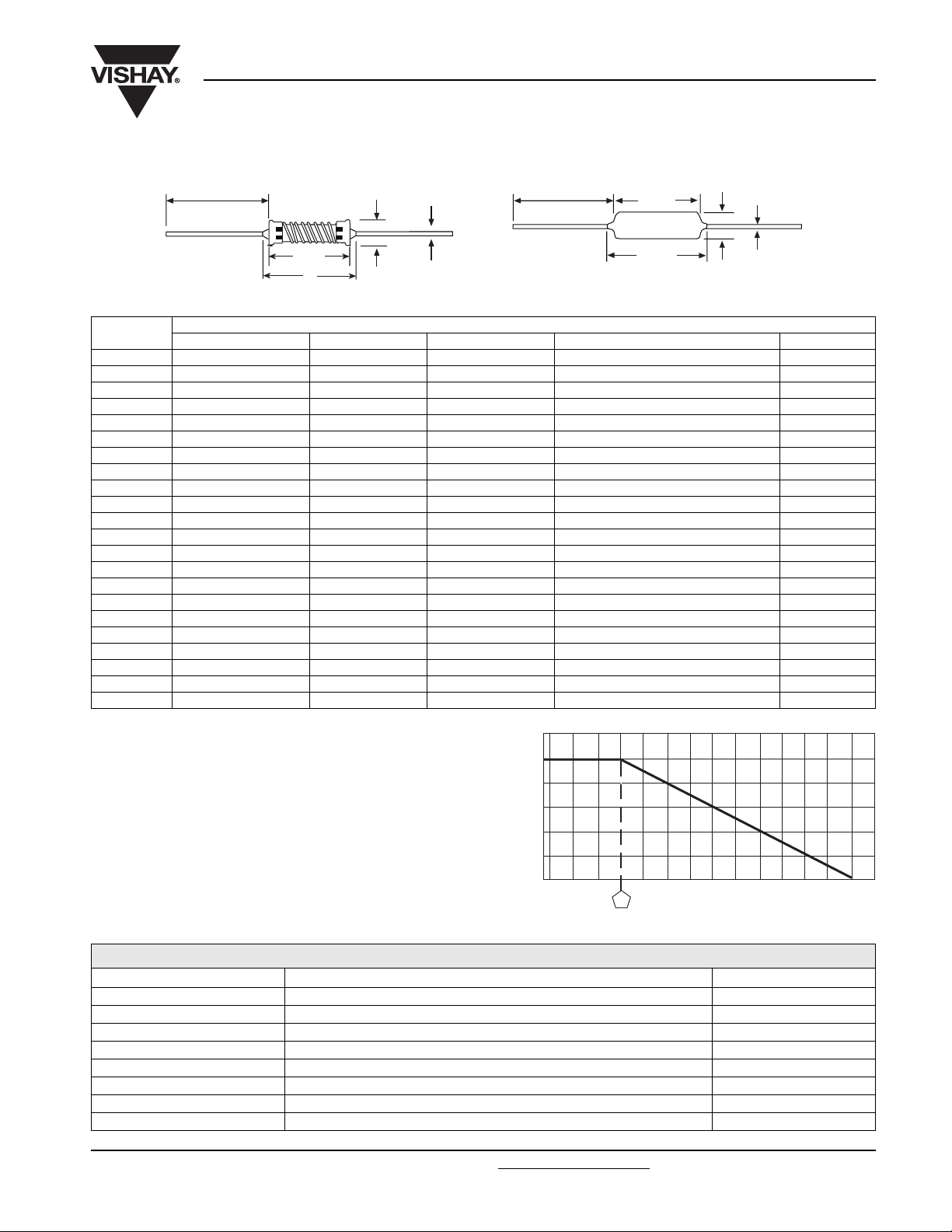
DIMENSIONS in inches [millimeters]
[1.625 ± 0.125]
41.28 ± 3.15
Figure 1
Note
(1)
On some standard reel pack methods, the leads may be trimmed to a shorter length than shown.
GLOBAL
MODEL
A ± 0.031 [0.794] A’ (maximum) B ± 0.001 [0.025] C FIGURE
(1)
A
A'
C
B
[1.625 ± 0.125]
41.28 ± 3.15
Figure 2
DIMENSIONS in inches [millimeters]
CA0001 0.400 [10.16] 0.460 [11.68] 0.032 [0.813] 0.170 maximum [4.32 maximum] 2
CA0002 0.570 [14.48] 0.630 [16.00] 0.032 [0.813] 0.170 maximum [4.32 maximum] 2
CA4050 0.500 [12.70] 0.594 [15.09] 0.032 [0.813] 0.140 ± 0.031 [3.56 ± 0.794] 1
CA4055 0.550 [13.97] 0.644 [16.36] 0.032 [0.813] 0.140 ± 0.031 [3.56 ± 0.794] 1
CA4060 0.600 [15.24] 0.694 [17.63] 0.032 [0.813] 0.140 ± 0.031 [3.56 ± 0.794] 1
CA4070 0.700 [17.78] 0.794 [20.17] 0.032 [0.813] 0.140 ± 0.031 [3.56 ± 0.794] 1
CA4080 0.800 [20.32] 0.894 [22.71] 0.032 [0.813] 0.140 ± 0.031 [3.56 ± 0.794] 1
CA4090 0.900 [22.86] 0.994 [25.25] 0.032 [0.813] 0.140 ± 0.031 [3.56 ± 0.794] 1
CA4100 1.00 [25.40] 1.094 [27.79] 0.032 [0.813] 0.140 ± 0.031 [3.56 ± 0.794] 1
CA4150 1.50 [38.10] 1.594 [40.49] 0.032 [0.813] 0.140 ± 0.031 [3.56 ± 0.794] 1
CA4200 2.00 [50.80] 2.094 [53.19] 0.032 [0.813] 0.140 ± 0.031 [3.56 ± 0.794] 1
CA4220 2.20 [55.88] 2.294 [58.27] 0.032 [0.813] 0.140 ± 0.031 [3.56 ± 0.794] 1
CA5050 0.500 [12.70] 0.625 [15.88] 0.036 [0.914] 0.170 ± 0.031 [4.32 ± 0.794] 2
CA5055 0.550 [13.97] 0.675 [17.15] 0.036 [0.914] 0.170 ± 0.031 [4.32 ± 0.794] 2
CA5060 0.600 [15.24] 0.725 [18.42] 0.036 [0.914] 0.170 ± 0.031 [4.32 ± 0.794] 2
CA5070 0.700 [17.78] 0.825 [20.96] 0.036 [0.914] 0.170 ± 0.031 [4.32 ± 0.794] 2
CA5080 0.800 [20.32] 0.925 [23.50] 0.036 [0.914] 0.170 ± 0.031 [4.32 ± 0.794] 2
CA5090 0.900 [22.86] 1.025 [26.04] 0.036 [0.914] 0.170 ± 0.031 [4.32 ± 0.794] 2
CA5100 1.00 [25.40] 1.125 [28.58] 0.036 [0.914] 0.170 ± 0.031 [4.32 ± 0.794] 2
CA5150 1.50 [38.10] 1.625 [41.28] 0.036 [0.914] 0.170 ± 0.031 [4.32 ± 0.794] 2
CA5200 2.00 [50.80] 2.125 [53.98] 0.036 [0.914] 0.170 ± 0.031 [4.32 ± 0.794] 2
CA5220 2.20 [55.88] 2.325 [59.06] 0.036 [0.914] 0.170 ± 0.031 [4.32 ± 0.794] 2
(1)
A
'
A
B
C
MATERIAL SPECIFICATIONS
Element: Copper-nickel alloy or nickel-chrome alloy,
120
100
depending on resistance value
Core: Woven fiberglass
Coating: Special high temperature silicone (CA4000 series
is not coated)
Terminals: Tin/lead electroplated copper (Lead (Pb)-free
will be 100 % tin)
End Caps: Tin plated steel
Part Marking: DALE, model, wattage, value, tolerance,
date code
80
60
40
RATED POWER IN %
20
0
- 65 - 25 75 125 175 225 275
25
AMBIENT TEMPERATURE IN °C
Derating
PERFORMANCE
TEST CONDITIONS OF TEST TEST LIMITS (EIA RS-344)
Thermal Shock - 55 °C to + 275 °C, 5 cycles, 30 min dwell time ± (5.0 % + 0.05 Ω) ΔR
Short Time Overload 5 x rated power for 5 s ± (4.0 % + 0.05 Ω) ΔR
Dielectric Withstanding Voltage 600 V
Low Temperature Storage - 65 °C, full rated working voltage for 45 min ± (3.0 % + 0.05 Ω) ΔR
Humidity 75 °C, 90 % - 100 % RH, 240 h ± (5.0 % + 0.05 Ω) ΔR
Load Life 1000 h at rated power, + 25 °C, 1.5 h “ON”, 0.5 h “OFF” ± (10.0 % + 0.05 Ω) ΔR
Terminal Strength 10 pounds for 30 s; body twisted about axis, 3 360° rotations ± (2.0 % + 0.05 Ω) ΔR
Resistance to Solder Heat Terminal immersed 3.5 s in molten solder at 1/8" to 3/16" from body ± (4.0 % + 0.05 Ω) ΔR
Document Number: 30214 For technical questions, contact: ww2aresistors@vishay.com
Revision: 31-Oct-07 35
, (CA0001, CA0002) for 1 min ± (2.0 % + 0.05 Ω) ΔR
AC
www.vishay.com
Page 3

Legal Disclaimer Notice
Vishay
Disclaimer
All product specifications and data are subject to change without notice.
Vishay Intertechnology, Inc., its affiliates, agents, and employees, and all persons acting on its or their behalf
(collectively, “Vishay”), disclaim any and all liability for any errors, inaccuracies or incompleteness contained herein
or in any other disclosure relating to any product.
Vishay disclaims any and all liability arising out of the use or application of any product described herein or of any
information provided herein to the maximum extent permitted by law. The product specifications do not expand or
otherwise modify Vishay’s terms and conditions of purchase, including but not limited to the warranty expressed
therein, which apply to these products.
No license, express or implied, by estoppel or otherwise, to any intellectual property rights is granted by this
document or by any conduct of Vishay.
The products shown herein are not designed for use in medical, life-saving, or life-sustaining applications unless
otherwise expressly indicated. Customers using or selling Vishay products not expressly indicated for use in such
applications do so entirely at their own risk and agree to fully indemnify Vishay for any damages arising or resulting
from such use or sale. Please contact authorized Vishay personnel to obtain written terms and conditions regarding
products designed for such applications.
Product names and markings noted herein may be trademarks of their respective owners.
Document Number: 91000 www.vishay.com
Revision: 18-Jul-08 1
 Loading...