

Page 1

6121 Baker Road,
Suite 108
Minnetonka, MN 55345
www.chtechnology.com
Phone (952) 933-6190
Fax (952) 933-6223
1-800-274-4284
Thank you for downloading this document from C&H Technology, Inc.
Please contact the C&H Technology team for the following questions -
Technical
Application
Assembly
Availability
Pricing
Phone – 1-800-274-4284
E-Mail – sales@chtechnology.com
www.chtechnology.com - SPECIALISTS IN POWER ELECTRONIC COMPONENTS AND ASSEMBLIES - www.chtechnology.com
Page 2
BSI
Vishay Sfernice
Molded and Insulated Wirewound Power
Resistors Axial Leads
FEATURES
• 1 W to 10 W
• NF C 83-210
• GAM T1 LNZ
• Excellent stability = typical drift ± 1 % after 2000 h
• High power = up to 10 W (25 °C)
• Low ohmic values = 0.01 Ω available
• Electrical insulation
• Climatic protection
BSI style resistors comply with the most stringent requirements of the NF C 83-210. 8 styles covering the power range from
1 W to 10 W
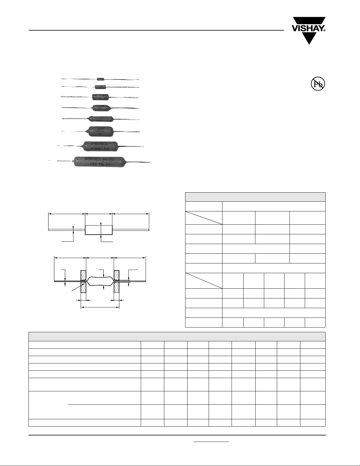
DIMENMSIONS in millimeters
MOLDED
25 min.
Ø C
25 min.
Ø E
45° chamfer
max. 0.25 deep
INSULATE D
4
L max.
A
Ø B
A
Ø B
25 min.
25 min.
± 0.02
Ø 1.2
4
DIMENSIONS in millimeters
PROTECTION MOLDED
Style
Dim.
A 6.5 ± 0.2 10 ± 0.2 15 ± 0.5
Ø B 2.4 ± 0.1 3.7 ± 0.1 5.6 ± 0.2
Ø C ± 0.1 0.6 0.8
Weight in g 0.3 0.45 1.3
PROTECTION INSULATED
Style
Dim.
A 16 ± 2 23 ± 2 23 ± 2 32 ± 2 47 ± 2
Ø B 5 ± 1 5 ± 1 9 ± 1 9 ± 1 9 ± 1
Ø C ± 0.1 0.8
Weight in g 1.6 2.5 6 7.5 10
58 BSI 63 BSI 68 BSI
516 BSI 523 BSI 923 BSI 932 BSI 947 BSI
RoHS
COMPLIANT
TECHNICAL SPECIFICATIONS
VISHAY SFERNICE MODEL AND STYLE 58 BSI 63 BSI 68 BSI 516 BSI 523 BSI 923 BSI 932 BSI 947 BSI
NF C 83-210 Conformity RP 8 RP 7 RP 4 - - RP 5 - RP 6
LNZ yes yes yes - - yes - yes
GAM-T-1 yes yes yes - - yes - yes
Power Rating at + 25 °C 1 W 2 W 3 W 4 W 5 W 6 W 8 W 10 W
Ohmic Range
Ohmic Range
in Relation to
Temperature
Coefficient
Limiting Element Voltage 50 V 120 V 200 V 200 V 250 V 300 V 500 V 750 V
www.vishay.com For technical questions, contact: sfer@vishay.com
47 Revision: 25-Mar-07
± 100 ppm/°C
± 300 ppm/°C
± 0.5 %
± 5 %
± 1 %
± 5 %
0.1 Ω
2 kΩ
0.1 Ω
2 kΩ
0.025 Ω
4 kΩ
0.1 Ω
4 kΩ
0.025 Ω
< 0.1 Ω
0.01 Ω
15 kΩ
0.1 Ω
15 kΩ
0.01 Ω
< 0.1 Ω
0.01 Ω
20 kΩ
0.1 Ω
20 kΩ
0.01 Ω
< 0.1 Ω
0.015 Ω
40 kΩ
0.1 Ω
40 kΩ
0.015 Ω
< 0.1 Ω
0.02 Ω
60 kΩ
0.1 Ω
60 kΩ
0.02 Ω
< 0.1 Ω
0.035 Ω
100 kΩ
0.1 Ω
100 kΩ
0.035 Ω
< 0.1 Ω
Document Number: 50011
0.06 Ω
150 kΩ
0.1 Ω
150 kΩ
0.06 Ω
< 0.1 Ω
Page 3

BSI
Molded and Insulated Wirewound Power
Resistors Axial Leads
PERFORMANCE
TESTS CONDITIONS
Dielectric W/s Voltage
Short Time Overload
1000 V
500 V
5 Pn/5 s for Pn < 5 W 10
for 923... 947
RMS
for 58... 523
RMS
Pn/5 s for Pn ≥ 5 W
MIL-R-26 E NF C 83-210
± (0.1 % + 0.05 Ω) - ± (0.1 % + 0.05 Ω)
± (0.2 % + 0.05 Ω) ± 0.25 % + 0.05 Ω ± (0.1 % + 0.05 Ω)
NF C 83-210
Climatic Sequence
fasc. 19 A - 55 °C/+ 200 °C
5 cycles
Humidity (Steady State)
NF C 83-210
fasc. 3 A 56 days 95 % R.H.
Load at 100 % P followed
Thermal Shock
by cold temp. exposure
± (0.2 % + 0.05 Ω) ± 0.25 % + 0.05 Ω ± (0.1 % + 0.05 Ω)
at - 55 °C
MIL-STD-202
Vibration
Method 204 - Test D: 20 g
± (0.1 % + 0.05 Ω) ± 0.25% + 0.05 Ω ± (0.05 % + 0.05 Ω)
10/2000 Hz
Load Life
Moisture Resistance
MIL-STD-202
Method 108PR 2000 h
MIL-STD-202
Method 106
± (0.5 % + 0.05 Ω)
± (0.2 % + 0.05 Ω)
Insulation resistance
> 100 MΩ
High Temperature 250 h at + 275 °C ± (0.5 % + 0.05 Ω)
Shock
MIL-STD-202
100 g Method 205 - Test C
± (0.1 % + 0.05 Ω) ± 0.25 % + 0.05 Ω ± (0.05 % + 0.05 Ω)
REQUIREMENTS
-
-
± 0.5 % + 0.05 Ω
Insulation R >100 MΩ
± 0.5 % + 0.05
Insulation R > 100 M
± 0.5% + 0.05 Ω
Insulation R ≥ 1 GΩ
-
± 0.5 % + 0.05 Ω
Insulation R ≥ 1 GΩ
Vishay Sfernice
TYPICAL VALUES
AND DRIFTS
± (0.3 % + 0.05 Ω) Ins.
resistance > 10
± (0.3 % + 0.05) Ins.
resistance > 10
± (1 % + 0.05 Ω)
± (1 % + 0.05 Ω) Ins.
resistance > 10
± (0.3 % + 0.05 Ω)
3
MΩ
3
MΩ
3
MΩ
POWER RATING CHART TEMPERATURE RISE
8 63 68 516 523 923 932 947
125
100
REWOP
75
DETAR
50
%
37
25
0
0 50 100 150 200 250 275 300 350
AMBIENT TEMPERATURE IN DEGREES CELSIUS
5
250
C° NI
200
E
RUT
A
REP
150
M
E
T
TOPS
100
T
OH
50
0
0 1 2 3 4 5 6 7 8 9 10 11 12 13 14 15
RATED POWER IN WATTS
MARKING
GEKA trademark, model, style, nominal resistance (in Ω), tolerance (in %), manufacturing date.
Because of lack of space, small styles are marked with ohmic value (in Ω), and tolerance (in %) only.
ORDERING INFORMATION
BSI 63 U22 2 % ± 100 ppm/°C TR300 e1
MODEL STYLE OHMIC VALUE TOLERANCE TEMPERATURE
COEFFICIENT
PACKING LEAD (Pb)-FREE
SAP PART NUMBERING GUIDELINES
BSI 063 R2200 G R22
MODEL STYLE OHMIC VALUE TOLERANCE PACKING
Document Number: 50011 For technical questions, contact: sfer@vishay.com
Revision: 25-Mar-07 48
www.vishay.com
 Loading...