

Page 1

6121 Baker Road,
Suite 108
Minnetonka, MN 55345
www.chtechnology.com
Phone (952) 933-6190
Fax (952) 933-6223
1-800-274-4284
Thank you for downloading this document from C&H Technology, Inc.
Please contact the C&H Technology team for the following questions -
Technical
Application
Assembly
Availability
Pricing
Phone – 1-800-274-4284
E-Mail – sales@chtechnology.com
www.chtechnology.com - SPECIALISTS IN POWER ELECTRONIC COMPONENTS AND ASSEMBLIES - www.chtechnology.com
Page 2
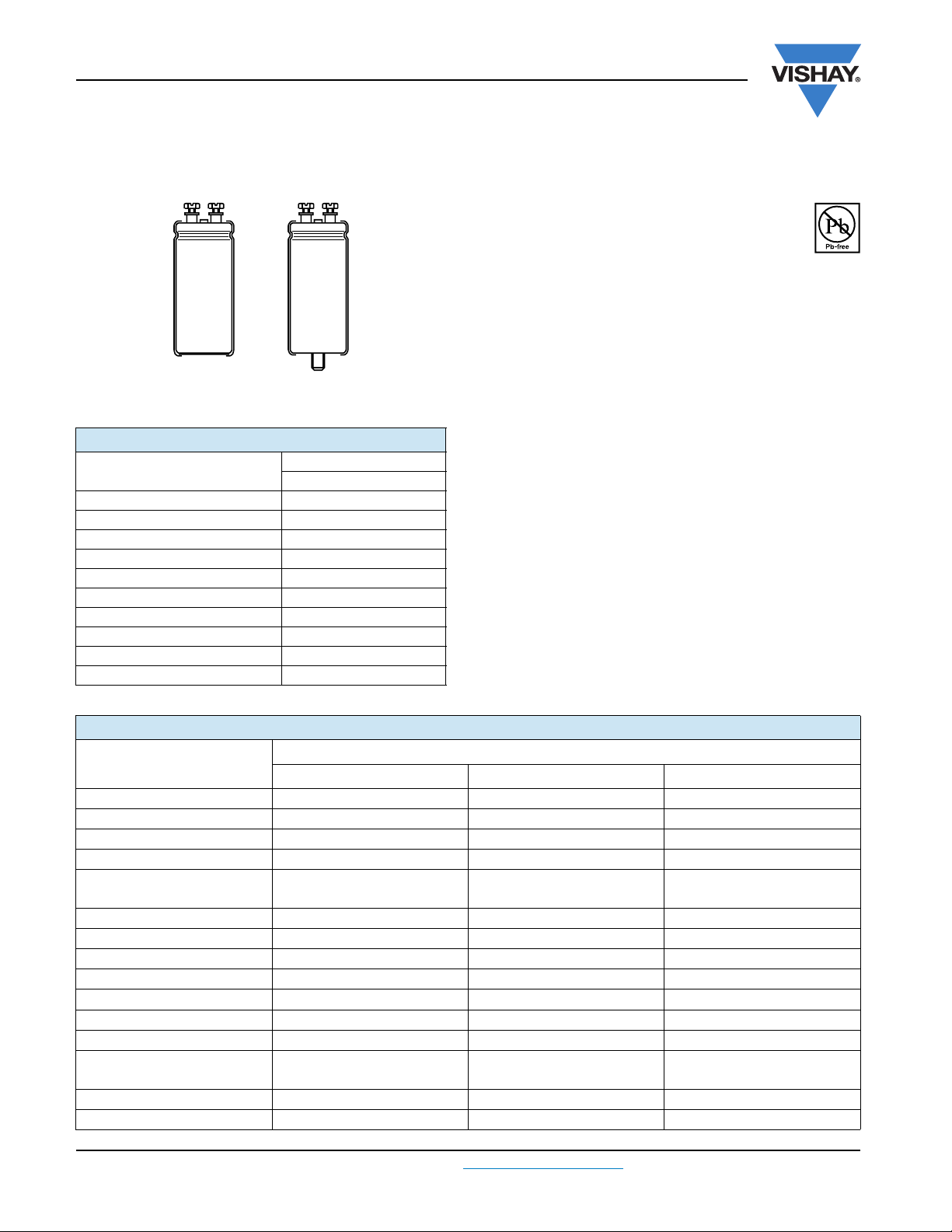
500 PGP-ST
Vishay BCcomponents
Aluminum Capacitors
Power General Purpose Screw Terminals
ST STB
Fig.1 Component outline
QUICK REFERENCE DATA
DESCRIPTION
Nominal case size (Ø D x L in mm)
Rated capacitance range, C
Tolerance on C
Rated voltage range, U
Category temperature range - 40 °C to + 85 °C
Endurance test at 85 °C 2000 hours
Useful life at 85 °C 2000 hours
Shelf life at 0 V, 85 °C 500 hours
Based on sectional specification IEC 60384-4/EN 130300
Climatic category IEC 60068 40/085/56
R
R
R
VAL UE
500
50 x 80 to 90 x 220
1000 µF to 15 000 µF
± 20 %
400 V to 450 V
FEATURES
• Polarized aluminum electrolytic capacitors,
non-solid electrolyte
• Large types, cylindrical aluminum case,
insulated with a blue sleeve
RoHS
COMPLIANT
• Pressure relief in the sealing disc
• Efficient design
• Compliant to RoHS directive 2002/95/EC
APPLICATIONS
• UPS
• Energy storage in medical or industrial pulse systems
MARKING
The capacitors are marked with the following information:
• Rated capacitance (in µF)
• Tolerance on rated capacitance, code letter in accordance
with IEC 60062 (M for ± 20 %)
• Rated voltage (in V)
• Date code
• Name of manufacturer
• Code for factory of origin
• Code number
SELECTION CHART FOR CR, UR AND RELEVANT NOMINAL CASE SIZES (Ø D x L in mm)
(V)
U
C
R
(µF)
1000
1200
1500
1800
2200
2700
3300
3900
4700
5600
6800
8200
10 000
12 000
15 000
www.vishay.com For technical questions, contact: aluminumcaps2@vishay.com
164 Revision: 25-May-09
400 420 450
50 x 80 50 x 80 50 x 80
50 x 80 50 x 80 50 x 80
50 x 105 50 x 105 50 x 105
50 x 105 50 x 105 50 x 105
50 x 105
65 x 105
65 x 105 65 x 105 65 x 105
65 x 105 65 x 105 76 x 105
65 x 105 76 x 105 76 x 105
76 x 105 76 x 114 76 x 114
76 x 114 - 76 x 146
76 x 146 76 x 146 90 x 146
90 x 146 90 x 146 76 x 220
76 x 220
90 x 146
76 x 220 - 90 x 220
90 x 220 90 x 220 -
R
65 x 105 65 x 105
76 x 220 76 x 220
Document Number: 28390
Page 3
500 PGP-ST
Aluminum Capacitors
Vishay BCcomponents
Power General Purpose Screw Terminals
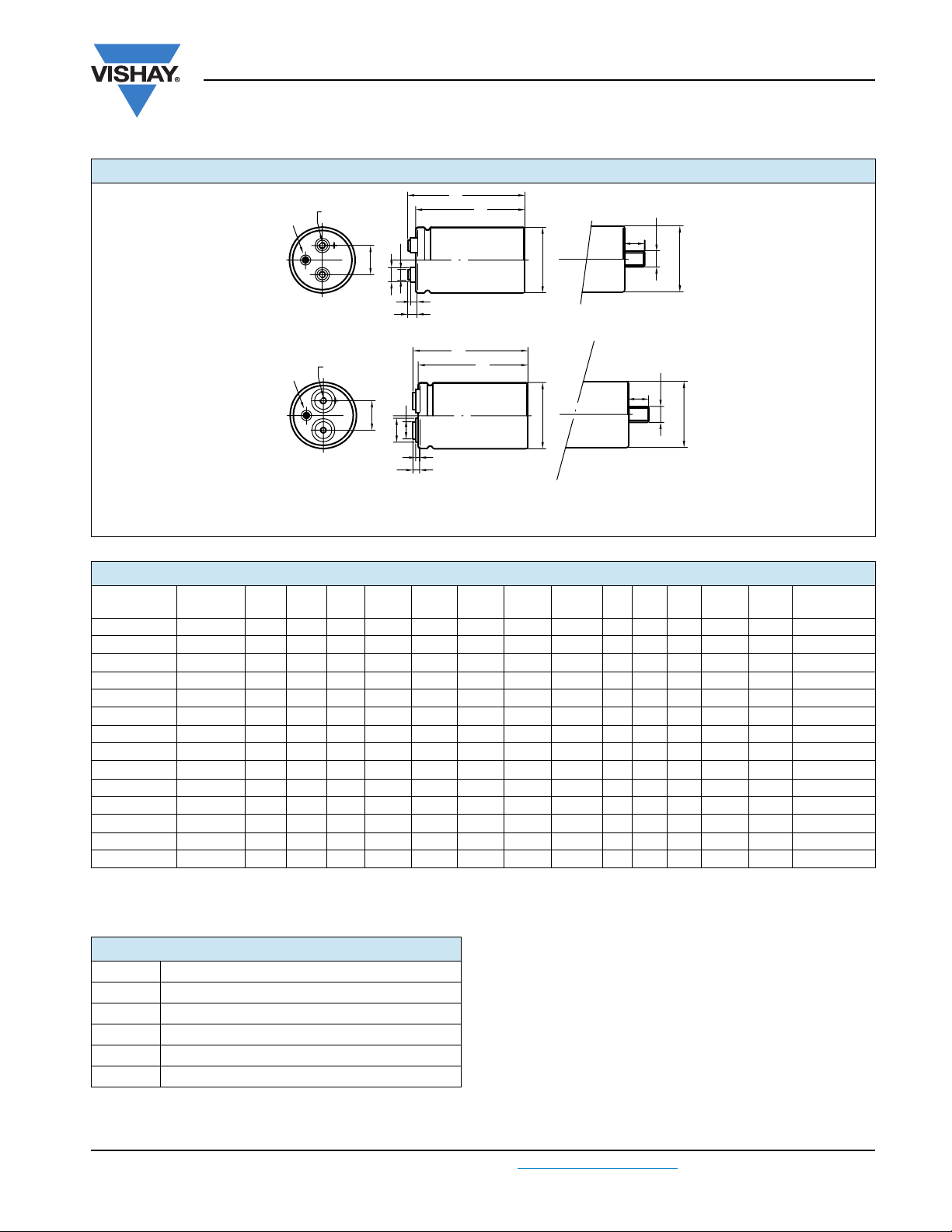
DIMENSIONS in millimeters AND AVAILABLE FORMS
L
t
Safety
A
Fig. 2A: Standard M5 disc: screw terminal (ST) and screw terminal bolt nut (STB)
Safety
B
Vent
Vent
Thread M x S
P
Thread M x S
P
d1
B
H
T
d
1
B
H
Fig. 2B: High current M6 disc: screw terminal (ST) and screw terminal bolt nut (STB)
Maximum permissible torque which may be applied to the termination screws: 2 Nm for M5; 2.5 Nm for M6
For accessories refer to datasheet “Mounting Accessories”.
The capacitors are delivered with screws and washers.
L
D
L
t
L
D
T
M
b
l
b
D
M
b
l
b
D
Tab l e 1
DIMENSIONS in millimeters, MASS AND PACKAGING QUANTITIES
MASS
DESIGN DRAWING L ± 1
± 1
L
D ± 1 P ± 0.3 T ± 0.2 H ± 0.3 B ± 0.3
t
d1 ± 0.1
MS - 0Mb
lb ± 0.1
50 x 80 2A 82.8 88.8 51.0 22.2 7.1 4.8 11.0 7.9 M5 9.5 M12 16.0 200 25
50 x 105 2A 104.8 110.8 51.0 22.2 7.1 4.8 11.0 7.9 M5 9.5 M12 16.0 300 25
65 x 105 2A 104.8 110.7 65.0 28.5 7.0 4.6 11.9 7.9 M5 9.5 M12 16.0 480 16
65 x 105 HC 2B 104.8 109.2 65.0 28.5 5.5 3.5 18.0 13.0 M6 8.5 M12 16.0 480 16
76 x 105 2A 105.8 111.7 76.4 31.8 7.0 4.6 11.7 7.9 M5 9.5 M12 16.0 700 12
76 x 105 HC 2B 105.8 110.2 76.4 31.8 5.5 3.5 18.3 13.0 M6 8.5 M12 16.0 700 12
76 x 114 2A 115.8 121.7 76.4 31.8 7.0 4.6 11.7 7.9 M5 9.5 M12 16.0 800 12
76 x 114 HC 2B 115.8 120.2 76.4 31.8 5.5 3.5 18.3 13.0 M6 8.5 M12 16.0 800 12
76 x 146 2A 145.8 151.7 76.4 31.8 7.0 4.6 11.7 7.9 M5 9.5 M12 16.0 1000 12
76 x 146 HC 2B 145.8 150.2 76.4 31.8 5.5 3.5 18.3 13.0 M6 8.5 M12 16.0 1000 12
76 x 220 2A 219.8 225.7 76.4 31.8 7.0 4.6 11.7 7.9 M5 9.5 M12 16.0 1500 10
76 x 220 HC 2B 219.8 224.2 76.4 31.8 5.5 3.5 18.3 13.0 M6 8.5 M12 16.0 1500 10
90 x 146 HC 2B 150.1 155.4 89.4 31.8 7.9 0.0 13.0 13.0 M6 10.0 M12 16.0 1300 10
90 x 220 HC 2B 218.1 223.4 89.4 31.8 7.9 0.0 13.0 13.0 M6 10.0 M12 16.0 2000 10
Note
• For bolt version holds:
1. L = L standard - 0.5 mm
= Lt standard - 0.5 mm
2. L
t
ELECTRICAL DATA
SYMBOL DESCRIPTION
C
R
I
R
I
L5
ESR max. equivalent series resistance at 100 Hz
Z max. impedance at 10 kHz
rated capacitance at 100 Hz, tolerance ± 20 %
rated RMS ripple current at 100 Hz, 85 °C
max. leakage current after 5 minutes at U
R
ORDERING EXAMPLE
Electrolytic capacitor 500 series
4700 µF/400 V; ± 20 %
Nominal case size: Ø 76 mm x 105 mm;
STB version; high post M5 disc
Ordering code: MAL2 500 56472E3
Former 12NC: 2222 500 56472
Note
• Unless otherwise specified, all electrical values in tables 2 and 3
apply at T
= 20 °C, P = 86 kPa to 106 kPa, RH = 45 % to 75 %
amb
Document Number: 28390 For technical questions, contact: aluminumcaps2@vishay.com
Revision: 25-May-09 165
PACKAGING
(g)
QUANTITIES
www.vishay.com
Page 4

500 PGP-ST
Vishay BCcomponents
Aluminum Capacitors
Power General Purpose Screw Terminals
Tab l e 2
ELECTRICAL DATA AND ORDERING INFORMATION
NOMINAL
C
U
R
100 Hz
(V)
(µF)
1000 50 x 80 4.2 11.2 0.80 125 98 26102E3 66102E3 - -
1200 50 x 80 4.5 12.0 0.96 107 85 16122E3 56122E3 - -
1500 50 x 105 5.1 14.1 1.20 86 68 16152E3 56152E3 - -
1800 50 x 105 5.6 15.1 1.44 73 59 16182E3 56182E3 - -
2200 50 x 105 6.3 17.1 1.76 58 46 16222E3 56222E3 - -
2200 65 x 105 7.4 19.9 1.76 58 46 26222E3 66222E3 46222E3 86222E3
2700 65 x 105 7.9 21.5 2.16 49 39 16272E3 56272E3 36272E3 76272E3
3300 65 x 105 8.9 24.0 2.64 39 31 16332E3 56332E3 36332E3 76332E3
400
3900 65 x 105 9.4 25.5 3.12 34 28 16392E3 56392E3 36392E3 76392E3
4700 76 x 105 11.1 30.0 3.76 30 25 16472E3 56472E3 36472E3 76472E3
5600 76 x 114 12.1 32.6 4.48 26 21 16562E3 56562E3 36562E3 76562E3
6800 76 x 146 13.6 36.6 5.44 21 18 16682E3 56682E3 36682E3 76682E3
8200 90 x 146 17.7 47.7 6.56 16 13 - - 36822E3 76822E3
10 000 76 x 220 17.0 45.8 8.00 15 12 16103E3 56103E3 36103E3 76103E3
10 000 90 x 146 19.3 52.2 8.00 13 11 - - 46103E3 86103E3
12 000 76 x 220 17.8 48.1 9.60 13 11 16123E3 56123E3 36123E3 76123E3
15 000 90 x 220 23.6 63.7 12.00 9 8 - - 36153E3 76153E3
1000 50 x 80 4.3 11.5 0.84 105 74 14102E3 54102E3 - -
1200 50 x 80 4.6 12.4 1.01 90 65 14122E3 54122E3 - -
1500 50 x 105 5.3 14.4 1.26 72 52 14152E3 54152E3 - -
1800 50 x 105 5.7 15.3 1.52 62 46 14182E3 54182E3 - -
2200 65 x 105 7.5 20.4 1.85 49 35 14222E3 54222E3 34222E3 74222E3
2700 65 x 105 8.1 21.9 2.27 42 31 14272E3 54272E3 34272E3 74272E3
420
3300 65 x 105 9.1 24.6 2.78 33 24 14332E3 54332E3 34332E3 74332E3
3900 76 x 105 10.7 28.8 3.28 29 22 14392E3 54392E3 34392E3 74392E3
4700 76 x 114 11.7 31.5 3.95 25 19 14472E3 54472E3 34472E3 74472E3
6800 76 x 146 13.8 37.2 5.72 18 14 14682E3 54682E3 34682E3 74682E3
8200 90 x 146 17.6 47.6 6.89 14 10 - - 34822E3 74822E3
10 000 76 x 220 17.3 46.6 8.40 13 10 14103E3 54103E3 34103E3 74103E3
15 000 90 x 220 24.1 65.0 12.60 8 6 - - 34153E3 74153E3
1000 50 x 80 4.2 11.3 0.90 126 88 17102E3 57102E3 - -
1200 50 x 80 4.5 12.1 1.08 100 76 17122E3 57122E3 - -
1500 50 x 105 5.3 14.2 1.35 79 61 17152E3 57152E3 - -
1800 50 x 105 5.9 15.9 1.62 64 48 17182E3 57182E3 - -
2200 65 x 105 7.4 20.0 1.98 54 41 17222E3 57222E3 37222E3 77222E3
2700 65 x 105 8.3 22.5 2.43 43 33 17272E3 57272E3 37272E3 77272E3
3300 76 x 105 9.9 26.8 2.97 37 28 17332E3 57332E3 37332E3 77332E3
450
3900 76 x 105 10.5 28.4 3.51 32 25 17392E3 57392E3 37392E3 77392E3
4700 76 x 114 11.5 31.0 4.23 28 22 17472E3 57472E3 37472E3 77472E3
5600 76 x 146 12.8 34.6 5.04 23 18 17562E3 57562E3 37562E3 77562E3
6800 90 x 146 16.6 44.8 6.12 17 13 - - 37682E3 77682E3
8200 76 x 220 16.0 43.3 7.38 16 13 17822E3 57822E3 37822E3 77822E3
10 000 76 x 220 17.0 45.8 9.00 14 11 17103E3 57103E3 37103E3 77103E3
12 000 90 x 220 22.1 59.5 10.80 10 8 - - 37123E3 77123E3
CASE
R
SIZE
Ø D x L
(mm)
I
R
120 Hz
85 °C
(A)
I
R
120 Hz
40 °C
(A)
I
L5
5min
(mA)
ESR
max.
120 Hz
(mΩ)
Z
max.
10 kHz
(mΩ)
MAL2500.......
HIGH POST
M5 DISC
ORDERING
CODE ST
ORDERING
CODE STB
MAL2500.......
HIGH CURRENT
M6 DISC
ORDERING
CODE ST
MAL2500.......
ORDERING
CODE STB
MAL2500.......
www.vishay.com For technical questions, contact: aluminumcaps2@vishay.com
166 Revision: 25-May-09
Document Number: 28390
Page 5

500 PGP-ST
Aluminum Capacitors
Vishay BCcomponents
Power General Purpose Screw Terminals
ADDITIONAL ELECTRICAL DATA
PARAMETER CONDITIONS VALUE
Voltage
Surge voltage ≥ 400 V versions U
Reverse voltage U
Current
Leakage current
Inductance
Equivalent series inductance (ESL)
Tab l e 3
After 1 minute at U
After 5 minutes at U
Case Ø D = 50 mm typ. 16 nH
Case Ø D = 65 mm typ. 19 nH
Case Ø D = 76 mm typ. 20 nH
Case Ø D = 90 mm typ. 20 nH
R
R
MULTIPLIER OF RIPPLE CURRENT (IR) AS A FUNCTION OF FREQUENCY
FREQUENCY (Hz)
60 0.70
100 0.95
120 1.00
500 1.20
1000 1.30
≥ 10 000 1.40
Tab l e 4
MULTIPLIER OF RIPPLE CURRENT (IR) AS A FUNCTION OF TEMPERATURE
TEMPERATURE (°C)
40 2.7
60 2.0
70 1.7
85 1.0
Tab l e 5
TEST PROCEDURES AND REQUIREMENTS
TEST
NAME OF TEST REFERENCE
Endurance IEC 60384-4/
EN130300
subclause 4.13
Useful life CECC 30301
subclause 1.8.1
Shelf life
(storage at
high temperature)
IEC 60384-4/
EN130300
subclause 4.17
T
=85 °C; UR applied;
amb
2000 hours
T
= 85 °C; UR and IR applied;
amb
2000 hours
T
= 85 °C; no voltage applied;
amb
500 hours
After test: U
24 hours to 48 hours before measurement
PROCEDURE
(quick reference)
to be applied for 30 minutes,
R
= 1.1 x U
s
rev
IL1≤ 0.006 CRxUR + 4 µA
IL5≤ 0.002 CRx UR + 4 µA
I
R
I
R
R
≤ 1 V
MULTIPLIER
500
MULTIPLIER
REQUIREMENTS
ΔC/C: ± 10 %
ESR ≤ 1.3 x spec. limit
Z ≤ 2 x spec. limit
I
≤ spec. limit
L5
ΔC/C: ± 30 %
ESR ≤ 3 x spec. limit
Z ≤ 3 x spec. limit
I
≤ spec. limit
L5
no short or open circuit,
no visible damage
total failure percentage: ≤ 3%
ΔC/C: ± 10 %
ESR ≤ 1.2 x spec. limit
I
≤ 2 x spec. limit
L5
Document Number: 28390 For technical questions, contact: aluminumcaps2@vishay.com
Revision: 25-May-09 167
www.vishay.com
Page 6

Legal Disclaimer Notice
Vishay
Disclaimer
All product specifications and data are subject to change without notice.
Vishay Intertechnology, Inc., its affiliates, agents, and employees, and all persons acting on its or their behalf
(collectively, “Vishay”), disclaim any and all liability for any errors, inaccuracies or incompleteness contained herein
or in any other disclosure relating to any product.
Vishay disclaims any and all liability arising out of the use or application of any product described herein or of any
information provided herein to the maximum extent permitted by law. The product specifications do not expand or
otherwise modify Vishay’s terms and conditions of purchase, including but not limited to the warranty expressed
therein, which apply to these products.
No license, express or implied, by estoppel or otherwise, to any intellectual property rights is granted by this
document or by any conduct of Vishay.
The products shown herein are not designed for use in medical, life-saving, or life-sustaining applications unless
otherwise expressly indicated. Customers using or selling Vishay products not expressly indicated for use in such
applications do so entirely at their own risk and agree to fully indemnify Vishay for any damages arising or resulting
from such use or sale. Please contact authorized Vishay personnel to obtain written terms and conditions regarding
products designed for such applications.
Product names and markings noted herein may be trademarks of their respective owners.
Document Number: 91000 www.vishay.com
Revision: 18-Jul-08 1
 Loading...