

Page 1

6121 Baker Road,
Suite 108
Minnetonka, MN 55345
www.chtechnology.com
Phone (952) 933-6190
Fax (952) 933-6223
1-800-274-4284
Thank you for downloading this document from C&H Technology, Inc.
Please contact the C&H Technology team for the following questions -
Technical
Application
Assembly
Availability
Pricing
Phone – 1-800-274-4284
E-Mail – sales@chtechnology.com
www.chtechnology.com - SPECIALISTS IN POWER ELECTRONIC COMPONENTS AND ASSEMBLIES - www.chtechnology.com
Page 2

Three Phase Bridge
Power Modules
D-34A
DESCRIPTION
A range of extremely compact, encapsulated three phase
bridge rectifiers offering efficient and reliable operation. They
are intended for use in general purpose and instrumentation
applications.
26MT../36MT..Series
Vishay High Power Products
FEATURES
• Universal, 3 way terminals: push-on, wrap
around or solder
• High thermal conductivity package, electrically
insulated case
• Center hole fixing
• Excellent power/volume ratio
• UL E300359 approved
• Gold plated terminals solderable using lead (Pb)-free
solder; solder alloy Sn/Ag/Cu (SAC305); solder
temperature 260 to 275 °C
• RoHS compliant
• Designed and qualified for industrial and consumer level
RoHS
COMPLIANT
MAJOR RATINGS AND CHARACTERISTICS
PARAMETER 26MT 36MT UNITS
I
O
I
FSM
2
I
V
T
t
RRM
J
at T
C
at 50 Hz 360 475
at 60 Hz 375 500
at 50 Hz 635 1130
at 60 Hz 580 1030
25 35 A
70 60 °C
100 to 1600 V
- 55 to 150 °C
ELECTRICAL SPECIFICATIONS
VOLTAGE RATINGS
TYPE NUMBER
26MT../36MT..
V
, MAXIMUM REPETITIVE
VOLTAGE
CODE
10 100 150
20 200 275
40 400 500
60 600 725
80 800 900
100 1000 1100
120 1200 1300
140 1400 1500
160 1600 1700
RRM
PEAK REVERSE VOLTAGE
V
V
, MAXIMUM NON-REPETITIVE
RSM
PEAK REVERSE VOLTAGE
V
I
RRM
AT T
A
A2s
MAXIMUM
MAXIMUM
J
mA
2
Document Number: 93565 For technical questions, contact: ind-modules@vishay.com
Revision: 25-May-07 1
www.vishay.com
Page 3

26MT../36MT..Series
Vishay High Power Products
Three Phase Bridge
Power Modules
FORWARD CONDUCTION
PARAMETER SYMBOL TEST CONDITIONS 26MT 36MT UNITS
Maximum DC output current
at T
C
Maximum peak, one-cycle
non-repetitive forward current
Initial T
= TJ maximum
J
Maximum I
Initial T
Maximum I
2
t for fusing
= TJ maximum
J
2
√t for fusing I2√tI2t for time tx = I2√t x √tx; 0.1 ≤ tx ≤ 10 ms, V
Low-level of threshold voltage V
High-level of threshold voltage V
Low-level forward slope resistance r
High-level forward slope resistance r
Maximum forward voltage drop V
Maximum DC reverse current I
RMS isolation voltage V
I
O
I
FSM
2
t
I
F(TO)1
F(TO)2
t1
t2
FM
RRM
INS
120° rect. conduction angle
t = 10 ms
t = 8.3 ms 375 500
t = 10 ms
t = 8.3 ms 314 420
t = 10 ms
t = 8.3 ms 580 1030
t = 10 ms
t = 8.3 ms 410 730
(16.7 % x π x I
( I > π x I
(16.7 % x π x I
( I > π x I
No voltage
reapplied
100 % V
RRM
reapplied
Initial T
= TJ maximum
No voltage
J
reapplied
100 % V
RRM
reapplied
= 0 V 6360 11 300 A2√s
RRM
< I < π x I
F(AV)
), at TJ maximum 1.13 1.03
F(AV)
< I < π x I
F(AV)
), at TJ maximum 5.2 5.0
F(AV)
), at TJ maximum 0.88 0.86
F(AV)
), at TJ maximum 7.9 6.3
F(AV)
TJ = 25 °C, IFM = 40 Apk - per single junction 1.26 1.19 V
TJ = 25 °C, per junction at rated V
RRM
TJ = 25 °C, all terminal shorted; f = 50 Hz, t = 1 s 2700 V
25 35 A
70 60 °C
360 475
300 400
635 1130
450 800
100 µA
A
A2s
V
mΩ
THERMAL AND MECHANICAL SPECIFICATIONS
PARAMETER SYMBOL TEST CONDITIONS 26MT 36MT UNITS
Maximum junction temperature range T
Maximum storage temperature range T
Maximum thermal resistance, junction to case R
Maximum thermal resistance, case to heatsink R
J
Stg
thJC
thCS
DC operation per bridge
(based on total power loss of bridge)
Mounting surface, smooth, flat and
greased
Approximate weight 20 g
Mounting torque ± 10 % Bridge to heatsink with screw M4 2.0 Nm
- 55 to 150
- 55 to 150
1.42 1.35
0.2 0.2
°C
K/W
www.vishay.com For technical questions, contact: ind-modules@vishay.com
Document Number: 93565
2 Revision: 25-May-07
Page 4
26MT../36MT..Series
Three Phase Bridge
Power Modules
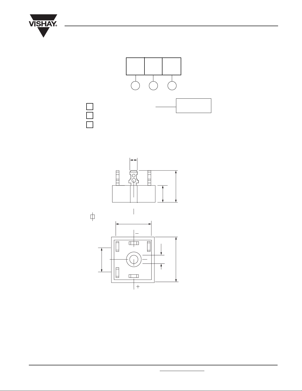
ORDERING INFORMATION TABLE
Device code
1
- Current rating code:
2
- Basic part number
3
- Voltage code (code x 10 = V
OUTLINE DIMENSIONS in millimeters (inches)
36 MT 160
132
6.3 x 0.8 (0.25 x 0.03)
26 = 25 A (Avg)
36 = 35 A (Avg)
)
RRM
Vishay High Power Products
16 (0.63)
25.3 (0.99) MAX.
~~
~
23 (0.90)
10
5.2
21 (0.83)
(0.39)
(0.20)
28.5 (1.12)
Suggested plugging force:
400 N maximum; axially applied to faston terminals
Not to scale
Document Number: 93565 For technical questions, contact: ind-modules@vishay.com
Revision: 25-May-07 3
www.vishay.com
Page 5

26MT../36MT..Series
Vishay High Power Products
160
26MT.. Series
140
120
100
Maximum Allowable
Case Temperature (°C)
~
80
60
030
5 101520
Total Output Current (A)
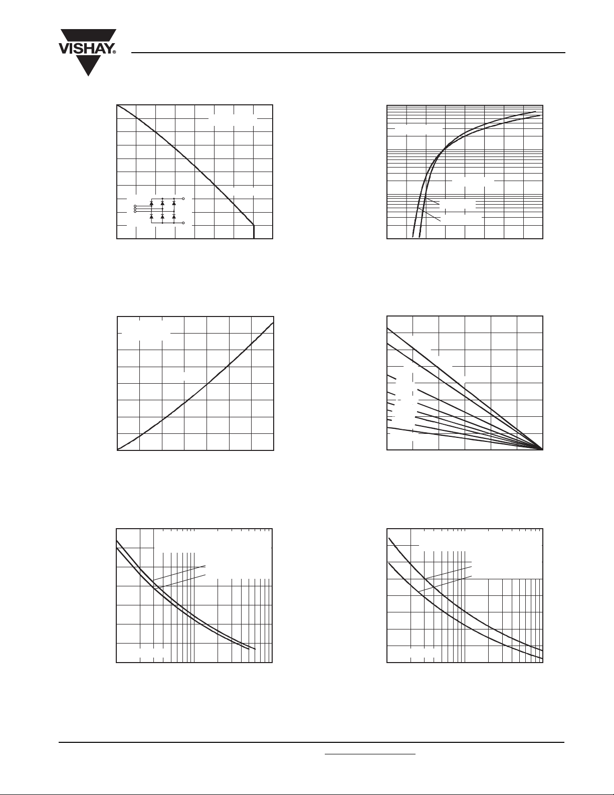
Fig. 1 - Current Ratings Characteristics Fig. 2 - Forward Voltage Drop Characteristics
55
26MT.. Series
50
= 150 °C
T
J
45
40
35
30
25
20
15
10
5
Maximum Total Power Loss (W)
0
0 5 10 20 25
Total Output Current (A)
+
-
120° (rect.)
Three Phase Bridge
Power Modules
120° (rect.)
25
Fig. 3 - Total Power Loss Characteristics
1000
26MT.. Series
100
Per junction
10
Instantaneous Forward Current (A)
1
0 0.5
TJ = 25 °C
TJ = 150 °C
1.0 1.5 2.0 2.5 3.0 3.5 4.0
Instantaneous Forward Voltage (V)
55
50
45
40
35
30
25
20
15
10
Maximum Total Power Loss (W)
1 K/W
2 K/W
3 K/W
4 K/W
5 K/W
7 K/W
10 K/W
5
0
0 25 50 100 150
R
thSA
= 0.7 K/W - ΔR
75 125
Maximum Allowable Ambient Temperature (°C)
320
300
280
260
240
220
200
180
160
140
Forward Current (A)
Peak Half Sine Wave
120
100
26MT.. Series
80
1 10 100
Number of Equal Amplitude Half Cycle
At any rated load condition and with
rated V
applied following surge.
RRM
Initial T
at 60 Hz 0.0083 s
at 50 Hz 0.0100 s
= 150 °C
J
400
360
320
280
240
200
160
Forward Current (A)
Peak Half Sine Wave
120
26MT.. Series
80
0.01 0.1 1
Maximum non repetitive surge current
versus pulse train duration.
= 150 °C
Initial T
No voltage reapplied
Rated V
J
RRM
reapplied
Pulse Drain Duration (s)
Current Pulses (N)
Fig. 4 - Maximum Non-Repetitive Surge Current Fig. 5 - Maximum Non-Repetitive Surge Current
www.vishay.com For technical questions, contact: ind-modules@vishay.com
Document Number: 93565
4 Revision: 25-May-07
Page 6
26MT../36MT..Series
150
130
110
90
Maximum Allowable
Case Temperature (°C)
~
70
50
040
10
5
15 25
Total Output Current (A)
Fig. 6 - Current Ratings Characteristics Fig. 7 - Forward Voltage Drop Characteristics
80
36MT.. Series
70
= 150 °C
T
J
60
50
40
30
20
10
Maximum Total Power Loss (W)
0
0 5 15 25 35
120° (rect.)
10 20 30
Total Output Current (A)
+
-
36MT.. Series
120° (rect.)
Three Phase Bridge
Power Modules
1000
100
10
Instantaneous Forward Current (A)
3520 30
80
70
60
50
40
30
20
10
Maximum Total Power Loss (W)
Maximum Allowable Ambient Temperature (°C)
Fig. 8 Total Power Loss Characteristics
Vishay High Power Products
36MT.. Series
Per junction
TJ = 25 °C
TJ = 150 °C
1
0 0.5
0
0 25 50 100 150
1.0 1.5 2.0 2.5 3.0 3.5 4.0
Instantaneous Forward Voltage (V)
R
thSA
= 0.7 K/W - ΔR
1 K/W
2 K/W
3 K/W
4 K/W
5 K/
W
7 K/W
10 K/
W
75 125
450
400
350
300
250
200
Forward Current (A)
Peak Half Sine Wave
150
36MT.. Series
100
1 10 100
Number of Equal Amplitude Half Cycle
At any rated load condition and with
rated V
applied following surge.
RRM
Initial T
at 60 Hz 0.0083 s
at 50 Hz 0.0100 s
= 150 °C
J
500
450
400
350
300
250
200
Forward Current (A)
Peak Half Sine Wave
150
36MT.. Series
100
0.01 0.1 1
Maximum non repetitive surge current
versus pulse train duration.
= 150 °C
Initial T
No voltage reapplied
Rated V
J
reapplied
RRM
Pulse Drain Duration (s)
Current Pulses (N)
Fig. 9 - Maximum Non-Repetitive Surge Current Fig. 10 - Maximum Non-Repetitive Surge Current
Document Number: 93565 For technical questions, contact: ind-modules@vishay.com
www.vishay.com
Revision: 25-May-07 5
Page 7
26MT../36MT..Series
Vishay High Power Products
10
Steady state value:
= 1.42 K/W
R
1
0.1
- Transient Thermal
Impedance (K/W)
0.01
thJC
Z
0.001
0.001 0.01 0.1 1 10
10
1
thJC
(DC operation)
Steady state value:
= 1.35 K/W
R
thJC
(DC operation)
Three Phase Bridge
Power Modules
Square Wave Pulse Duration (s)
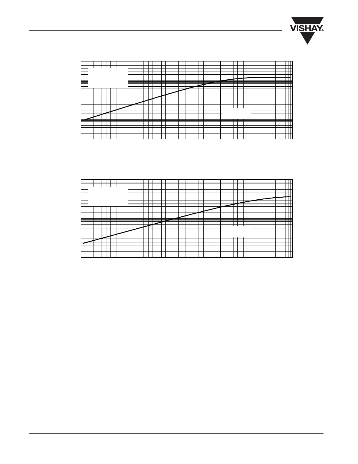
Fig. 11 - Thermal Impedance Z
Characteristics
thJC
26MT.. Series
per bridge
.
.
100
0.1
- Transient Thermal
Impedance (K/W)
0.01
thJC
Z
0.001
0.001 0.01 0.1 1 10
Square Wave Pulse Duration (s)
Fig. 12 Thermal Impedance Z
Characteristics
thJC
36MT.. Series
per bridge
.
.
100
www.vishay.com For technical questions, contact: ind-modules@vishay.com
Document Number: 93565
6 Revision: 25-May-07
 Loading...