

Page 1

6121 Baker Road,
Suite 108
Minnetonka, MN 55345
www.chtechnology.com
Phone (952) 933-6190
Fax (952) 933-6223
1-800-274-4284
Thank you for downloading this document from C&H Technology, Inc.
Please contact the C&H Technology team for the following questions -
Technical
Application
Assembly
Availability
Pricing
Phone – 1-800-274-4284
E-Mail – sales@chtechnology.com
www.chtechnology.com - SPECIALISTS IN POWER ELECTRONIC COMPONENTS AND ASSEMBLIES - www.chtechnology.com
Page 2

INPUT RECTIFIER DIODE
Document Number: 93501
www.vishay.com
1
Description/Features
The 20ETS.. rectifier SAFEIR series has been
optimized for very low forward voltage drop, with
moderate leakage. The glass passivation
technology used has reliable operation up to 150°C
junction temperature.
Typical applications are in input rectification and
these products are designed to be used with
International Rectifier Switches and Output
Rectifiers which are available in identical package
outlines.
Bulletin I2101 rev. D 12/01
SAFEIR Series
20ETS12, 20ETS12S
VF < 1V @ 10A
= 300A
I
FSM
V
800 to 1200V
RRM
Package Outline
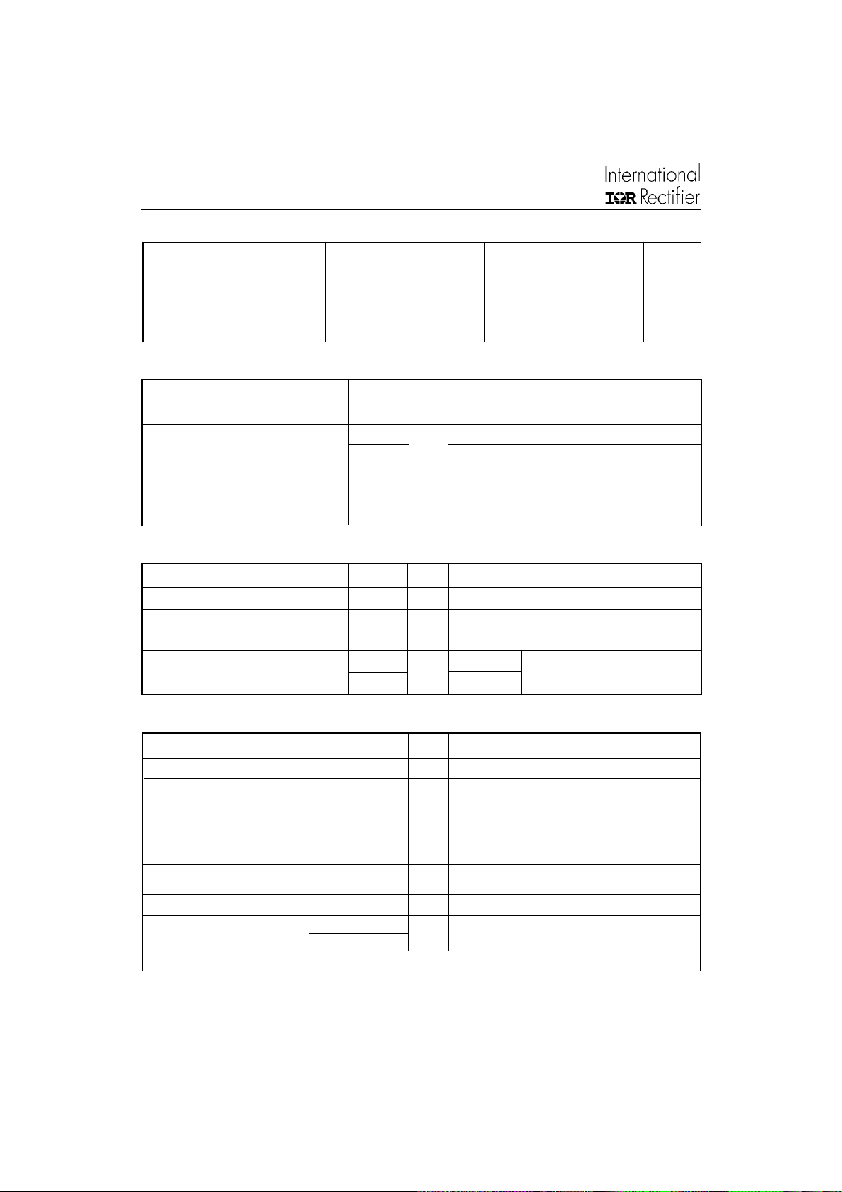
Major Ratings and Characteristics
Characteristics 20ETS.. Units
I
Sinusoidal
F(AV)
waveform
Range (*)
V
RRM
I
FSM
VF@ 10 A, TJ = 25°C 1.0 V
T
J
20 A
800 to 1200 V
300 A
- 40 to 150 °C
Output Current in Typical Applications
Capacitive input filter TA = 55°C, TJ = 125°C,
common heatsink of 1°C/W
TO-220AC
Package Outline
D2 Pak (SMD-220)
Single-phase Bridge Three-phase Bridge Units
16.3 21
A
Page 3
20ETS.., 20ETS..S SAFEIR Series
Document Number: 93501
www.vishay.com
2
Bulletin I2101 rev. D 12/01
Voltage Ratings
V
, maximum V
RRM
Part Number
peak reverse voltage peak reverse voltage 150°C
VVmA
20ETS08, 20ETS08S 800 900 1
20ETS12, 20ETS12S 1200 1300
Absolute Maximum Ratings
Parameters 20ETS.. Units Conditions
I
Max. Average Forward Current 20 A @ TC = 105° C, 180° conduction half sine wave
F(AV)
I
Max. Peak One Cycle Non-Repetitive 250 10ms Sine pulse, rated V
FSM
Surge Current 300 10ms Sine pulse, no voltage reapplied
I2t Max. I2t for fusing 316 10ms Sine pulse, rated V
442 10ms Sine pulse, no voltage reapplied
2
I
√t Max. I2√t for fusing 4420 A2√s t = 0.1 to 10ms, no voltage reapplied
A
A2s
Electrical Specifications
Parameters 20ETS.. Units Conditions
VFMMax. Forward Voltage Drop 1.1 V @ 20A, TJ = 25°C
r
Forward slope resistance 10.4 mΩ
t
V
Threshold voltage 0.85 V
F(TO)
IRMMax. Reverse Leakage Current 0.1 TJ = 25 °C
1.0 TJ = 150 °C
TJ = 150°C
mA
, maximum non repetitive I
RSM
RRM
RRM
VR = rated V
applied
applied
RRM
RRM
Thermal-Mechanical Specifications
Parameters 20ETS.. Units Conditions
TJMax. Junction Temperature Range - 40 to 150 °C
T
Max. Storage Temperature Range - 40 to 150 °C
stg
R
Max. Thermal Resistance Junction 1.3 °C/W DC operation
thJC
to Case
R
Max. Thermal Resistance Junction 62 °C/W (*) For D2Pak version
thJA
to Ambient
R
Typ. Thermal Resistance Case 0.5 °C/W Mounting surface, smooth and greased
thCS
to Heatsink
wt Approximate Weight 2 (0.07) g (oz.)
T Mounting Torque Min. 6 (5)
Max. 12 (10)
Case Style TO-220AC, D2Pak (SMD-220)
* When mounted on 1" square (650mm2) PCB of FR-4 or G-10 material 4 oz (140µm) copper 40°C/W
For recommended footprint and soldering techniques refer to application note # AN-994
Kg-cm
(Ibf-in)
Page 4
20ETS.., 20ETS..S SAFEIR Series
Document Number: 93501
www.vishay.com
3
Bulletin I2101 rev. D 12/01
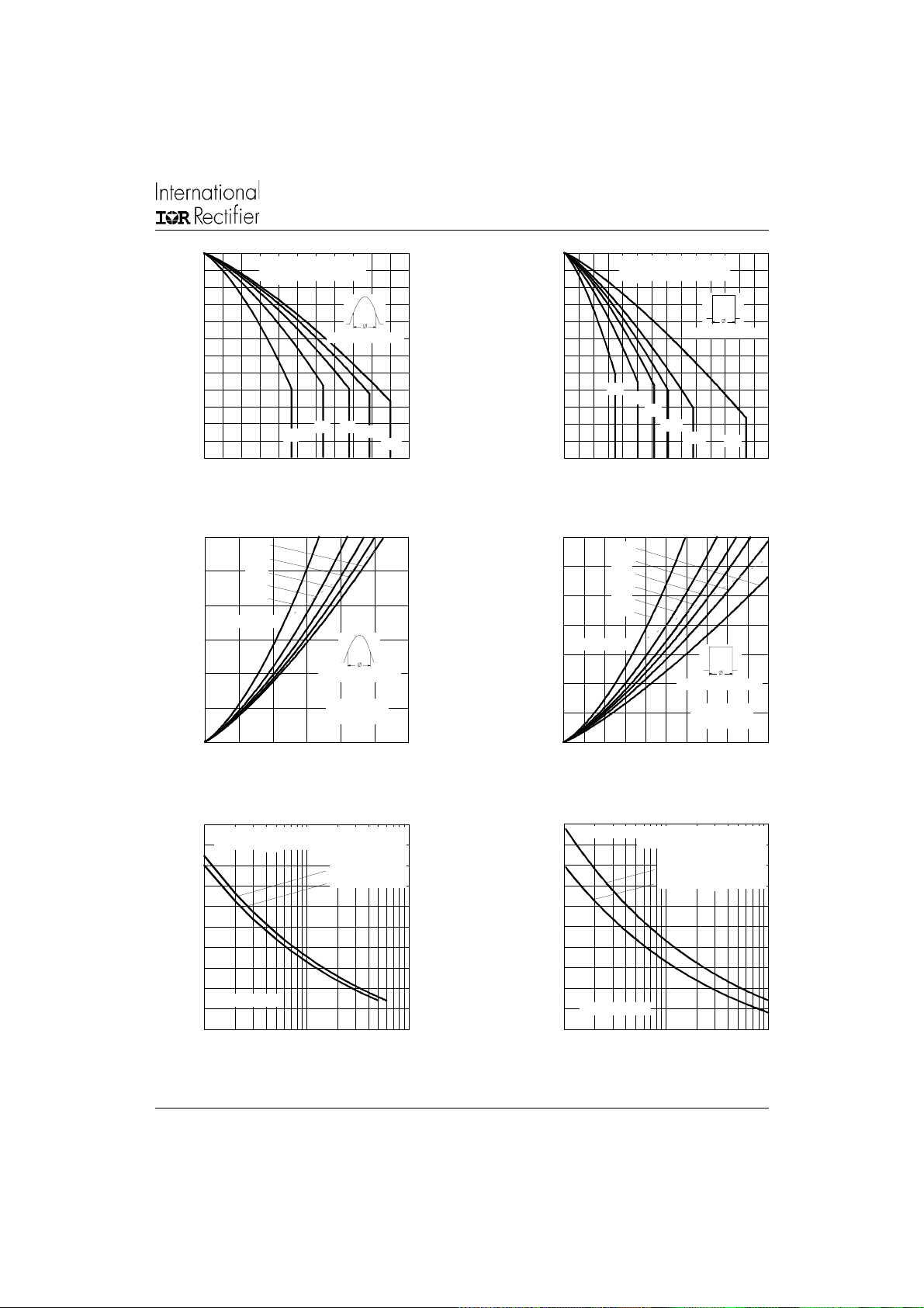
150
140
130
120
110
20ETS.. Series
R (DC) = 1.3 C/W
thJC
Conduction Angle
150
140
130
120
110
20ETS.. Series
R (D C ) = 1.3 C/W
thJC
30
60
90
100
Maximum Allowable Case Temperature ( C)
90
0 2 4 6 8 10 12 14 16 18 20 22
Average Forward Current (A)
30
60
90
120
180
100
90
Maximum Allowable Case Temperature ( C)
0 5 10 15 20 25 30 35
Average Forward Current (A)
Fig. 1 - Current Rating Characteristics Fig. 2 - Current Rating Characteristics
30
25
180
120
90
60
20
30
RMS Limit
15
10
5
0
Maximum Ave rage Forw ard Power Loss (W)
0 4 8 12162024
Conduction Angle
20ETS.. Series
T = 150 C
J
Averag e Fo rw a rd C urre nt (A)
Fig. 3 - Forward Power Loss Characteristics
35
30
25
DC
180
120
90
60
30
20
RMS Limit
15
10
5
0
Maximum Average Forward Power Loss (W)
0 5 10 15 20 25
Average Forward Current (A)
Fig. 4 - Forward Power Loss Characteristics
Conduction Period
120
180
Conduction Period
20ETS.. Series
T = 150 C
J
DC
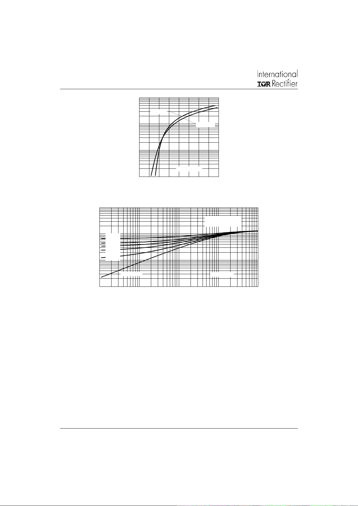
300
At Any Rated Load Condition And With
Rated V Applied Following Surge.
RRM
250
200
150
100
20ETS.. Series
Pe ak H alf Sine Wave Forw a rd Curre nt (A)
50
1 10 100
Number Of Equal Amplitude Half Cycle Current Pulses (N)
Initial T = 150 C
J
@ 60 Hz 0.0083 s
@ 50 Hz 0.0100 s
Fig. 5 - Maximum Non-Repetitive Surge Current
300
Ma ximum Non Repetitive Surge Current
250
Versus Pulse Train Duration.
Initial T = 150 C
No V o ltage Re a p p lied
Rated V Reapplied
J
RRM
200
150
100
20ETS.. Se ries
Peak Half Sine Wave Forward Current (A)
50
0.01 0.1 1
Pulse Train Duration (s)
Fig. 6 - Maximum Non-Repetitive Surge Current
Page 5
20ETS.., 20ETS..S SAFEIR Series
Document Number: 93501
www.vishay.com
4
Bulletin I2101 rev. D 12/01
1000
T = 25 C
J
100
10
Instantaneous Forward Current (A)
1
00.511.522.533.54
Instantaneous Forward Voltage (V)
20ETS.. Series
T = 150 C
J
Fig. 7 - Forward Voltage Drop Characteristics
10
Steady State Value
thJ C
1
D = 0.50
D = 0.33
D = 0.25
D = 0.17
D = 0.08
0.1
Sin g le Pulse
Transient Therm al Impedance Z ( C/W)
0.01
0.0001 0.001 0.01 0.1 1
Square W ave Pulse Duration (s)
Fig. 8 - Thermal Impedance Z
(DC Operation)
Characteristics
thJC
20ETS.. Series
Page 6
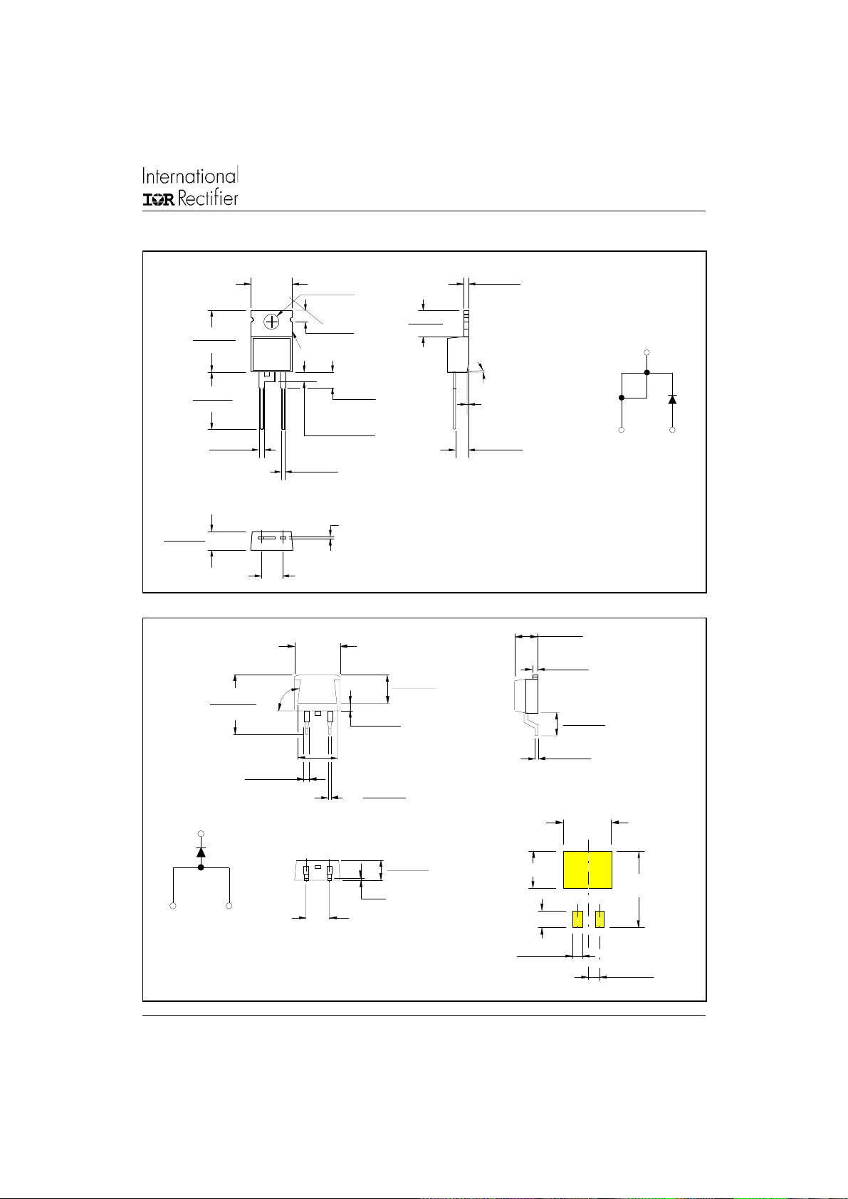
Outline Table
C
A
Document Number: 93501
www.vishay.com
5
20ETS.., 20ETS..S SAFEIR Series
Bulletin I2101 rev. D 12/01
14.09 (0.55)
13.47 (0.53)
4.57 (0.18)
4.32 (0.17)
Base
Cathode
1
node
15.24 (0.60)
14.84 (0.58)
1.40 (0.05)
1.15 (0.04)
15.49 (0.61)
14.73 (0.58)
2
Anode
10.54 (0.41)
1.40 (0.055)
3X
1.14 (0.045)
3
MAX.
1
1
93°
2
TERM 2
3
2.04 (0.080) MAX.
0.94 (0.04)
0.69 (0.03)
3
5.08 (0.20) REF.
10.16 (0.40)
REF.
13
3.78 (0.15)
3.54 (0.14)
2.92 (0.11)
2.54 (0.10)
3.96 (0.16)
3.55 (0.14)
0.61 (0.02) MAX.
8.89 (0.35)
2
DIA.
6.47 (0.25)
6.18 (0.24)
2.61 (0.10)
2.32 (0.09)
REF.
0.93 (0.37)
2X
0.69 (0.27)
4.57 (0.18)
4.32 (0.17)
0.61 (0.02) MAX.
5.08 (0.20) REF.
6.48 (0.25)
6.23 (0.24)
1.32 (0.05)
1.22 (0.05)
Cathode
2°
0.10 (0.004)
1
2.89 (0.11)
2.64 (0.10)
athode
TO-220AC
Dimensions in millimeters (inches)
4.69 (0.18)
4.20 (0.16)
1.32 (0.05)
1.22 (0.05)
5.28 (0.21)
4.78 (0.19)
0.55 (0.02)
0.46 (0.02)
MINIMUM RECOMMENDED FOOTPRINT
11.43 (0.45)
8.89 (0.35)
17.78 (0.70)
3.81 (0.15)
Base
2
3
Anode
D2Pak (SMD-220)
Dimensions in millimeters and inches
2.08 (0.08)
2X
2.54 (0.10)
2X
Page 7
20ETS.., 20ETS..S SAFEIR Series
Document Number: 93501
www.vishay.com
6
Bulletin I2101 rev. D 12/01
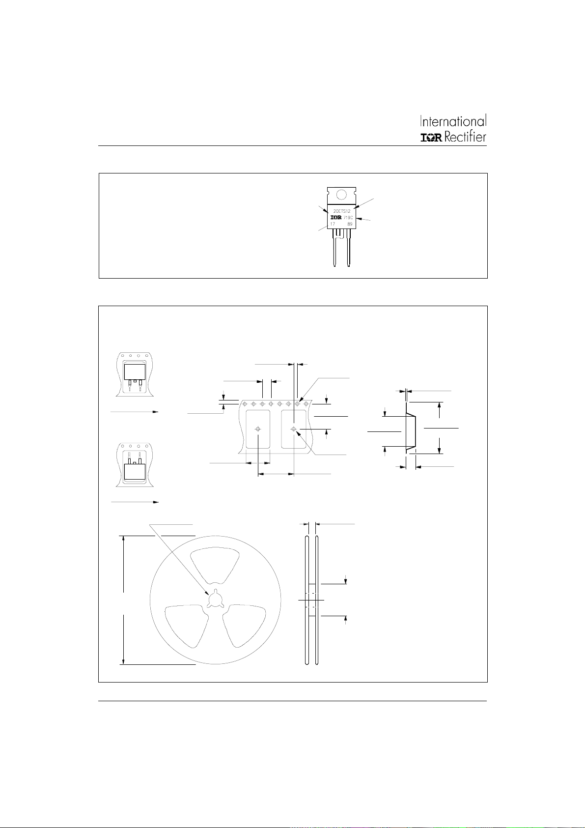
Marking Information
EXAMPLE: THIS IS A 20ETS12
LOT CODE 1789
ASSEMBLED ON WW 19, 1997
IN THE ASSEMBLY LINE "C"
Tape & Reel Information
TRR
FEED DIRECTION
TRL
1.8 5 (0.0 73 )
1.6 5 (0.0 65 )
4.10 (0. 161)
3.90 (0. 153)
10 .90 (0 .4 29)
10 .70 (0 .4 21)
INTERNATIONAL
1.60 (0.063)
1.50 (0.059)
RECTIFIER
LOGO
ASSEMBLY
LOT CODE
16 .10 (0.6 34)
15 .90 (0.6 26)
1.60 (0.063)
1.50 (0.059)
11 .60 (0.45 7)
11 .40 (0.44 9)
1.75 (0.069)
1.25 (0.049)
DIA.
DIA.
PART NUMBER
DATE CODE
YEAR 7 = 1997
WEEK 19
LINE C
15.42 (0.609)
15.22 (0.601)
0.368 (0.0145)
0.342 (0.0135)
24 .30 (0.95 7)
23 .90 (0.94 1)
4.7 2 (0.1 86)
4.5 2 (0.1 78)
FEED DIRECTION
360 (14.173)
DIA. MAX.
13.50 ( 0.532)
12.80 ( 0.504)
DIA.
Dimensions in millimeters and inches
26 .40 (1 .03 9)
24 .40 (0 .96 1)
60 (2 .36 2)
DIA. MIN.
SMD-2 20 Tape & R eel
When order ing, indicate th e part
number, part orientati on, and th e
quantity. Quantities are in multiples
of 8 00 piec es per re el fo r both
TRL a nd TRR.
Page 8

Ordering Information Table
Document Number: 93501
www.vishay.com
7
Device Code
20ETS.., 20ETS..S SAFEIR Series
Bulletin I2101 rev. D 12/01
20 E T S 12 S TRL
24
1
1 - Current Rating
2 - Circuit Configuration
3 - Package
4 - Type of Silicon
5 - Voltage code: Code x 100 = V
6 - S = TO-220 D2Pak (SMD-220) Version
7 - Tape and Reel Option
3
E = Single Diode
T = TO-220AC
S = Standard Recovery Rectifier
TRL = Left Reel
TRR = Right Orientation Reel
5
7
6
RRM
08 = 800V
12 = 1200V
This product has been designed and qualified for Industrial Level.
Data and specifications subject to change without notice.
Qualification Standards can be found on IR's Web site.
IR WORLD HEADQUARTERS: 233 Kansas St., El Segundo, California 90245, USA Tel: (310) 252-7105
TAC Fax: (310) 252-7309
12/01
 Loading...