

Page 1

6121 Baker Road,
Suite 108
Minnetonka, MN 55345
www.chtechnology.com
Phone (952) 933-6190
Fax (952) 933-6223
1-800-274-4284
Thank you for downloading this document from C&H Technology, Inc.
Please contact the C&H Technology team for the following questions -
Technical ● Application ● Assembly ● Availability ● Pricing
Phone – 1-800-274-4284
E-Mail – sales@chtechnology.com
www.chtechnology.com - SPECIALISTS IN POWER ELECTRONIC COMPONENTS AND ASSEMBLIES
-
www.chtechnology.com
Page 2

DO-203AA (DO-4)
1N3879(R), 1N3889(R), 6/12/16FL(R) Series
Vishay High Power Products
Fast Recovery Diodes
(Stud Version), 6/12/16 A
FEATURES
• Short reverse recovery time
• Low stored charge
• Wide current range
• Excellent surge capabilities
• Standard JEDEC types
• Stud cathode and stud anode versions
• Fully characterized reverse recovery conditions
• RoHS compliant
TYPICAL APPLICATIONS
• DC power supplies
RoHS
COMPLIANT
PRODUCT SUMMARY
I
F(AV)
6/12/16 A
• Converters
• Choppers
• Ultrasonic systems
• Freewheeling diodes
MAJOR RATINGS AND CHARACTERISTICS
•Inverters
SYMBOL CHARACTERISTICS
I
F(AV)
I
F(RMS)
I
FSM
2
I
t
2
I
√t 363 856 1452 1452 2290 I2√s
V
RRM
t
rr
T
J
Note
(1)
JEDEC registered values
TC = 100 °C 6
50 Hz 72 145 110 145 180
60 Hz 75
50 Hz 26 103 60 103 160
60 Hz 23 94 55 94 150
Range 50 to 400
Range - 65 to 150 °C
1N3879. TO
1N3883.
(1)
9.5199.519 25 A
(1)
1N3889. TO
1N3893.
(1)
12
(1)
150
(1)
See Recovery Characteristics table ns
6FL.. 12FL.. 16FL.. UNITS
61216A
115 150 190
50 to 1000 V
A
A2s
Document Number: 93138 For technical questions, contact: ind-modules@vishay.com
Revision: 26-Sep-08 1
www.vishay.com
Page 3

1N3879(R), 1N3889(R), 6/12/16FL(R) Series
Vishay High Power Products
Fast Recovery Diodes
(Stud Version), 6/12/16 A
ELECTRICAL SPECIFICATIONS
VOLTAGE RATINGS
, MAXIMUM
V
RRM
TYPE
NUMBER
VOLTAGE
CODE
REPETITIVE PEAK AND
OFF-STATE VOLTAGE
V
1N3879.
50 75
1N3880. 100 150
1N3881. 200 250
-
1N3882. 300 350
1N3883. 400 450
1N3889.
50 75
1N3890. 100 150
1N3891. 200 250
-
1N3892. 300 350
1N3893. 400 450
550 75
10 100 150
6FL..
12FL..
16FL..
20 200 275
40 400 500
60 600 725
80 800 950
100 1000 1250
Note
(1)
JEDEC registered values
V
RSM
NON-REPETITIVE
PEAK VOLTAGE
, MAXIMUM
V
I
MAXIMUM
RRM
AT T
= 25 °C
J
µA
(1)
15
(1)
25
I
MAXIMUM
RRM
AT T
= 100 °C
J
mA
(1)
1.0
(1)
3.0
50 - 6.0
I
MAXIMUM
RRM
AT T
= 150 °C
J
mA
(1)
3.0
(1)
5.0
FORWARD CONDUCTION
PARAMETER SYMBOL TEST CONDITIONS
Maximum average forward current
at case temperature
Maximum RMS current I
Maximum peak, one-cycle
non-repetitive forward current
Maximum I
Maximum I
2
t for fusing I2t
2
√t for fusing I2√t t = 0.1 to 10 ms, no voltage reapplied 363 856 1452 2290 A2√s
Maximum forward voltage drop V
I
F(AV)
F(RMS)
I
FSM
FM
180° conduction, half sine wave
DC
t = 10 ms
t = 8.3 ms 90 135 180 225
t = 10 ms
t = 8.3 ms
t = 10 ms
t = 8.3 ms 33 78 130 210
t = 10 ms
t = 8.3 ms 23 55 94 150
TJ = 25 °C; IF = Rated I
T
= 100 °C; IFM = π x rated I
C
No voltage
reapplied
100 % V
RRM
reapplied
No voltage
reapplied
100 % V
RRM
reapplied
F(AV)
Sinusoidal
half wave,
initial
T
= 150 °C
J
(DC)
F(AV)
1N3879.
1N3883.
(1)
6
100 100 100 100 °C
9.5 9.5 19 25
85 130 170 215
72 110 145 180
(1)
75
36 86 145 230
26 60 103 160
(1)
1.4
(1)
1.5
Note
(1)
JEDEC registered values
www.vishay.com For technical questions, contact: ind-modules@vishay.com
2 Revision: 26-Sep-08
6FL..
6
115
1.4
1.5
1N3889.
1N3893.
16FL.. UNITS
12FL..
(1)
12
16 A
A
(1)
150
190
A2s
(1)
(1)
1.4 V
1.5 V
1.4
1.5
Document Number: 93138
Page 4

1N3879(R), 1N3889(R), 6/12/16FL(R) Series
Fast Recovery Diodes
Vishay High Power Products
(Stud Version), 6/12/16 A
RECOVERY CHARACTERISTICS
6FL..
PARAMETER SYMBOL TEST CONDITIONS
TJ = 25 °C, IF = 1 A to VR = 30 V,
/dt = 100 A/µs
Maximum reverse
recovery time
Maximum peak
recovery current
t
I
RM(REC)IFM
dI
rr
F
= 25 °C, dIF/dt = 25 A/µs,
T
J
I
= π x rated I
FM
= π x rated I
F(AV)
F(AV)
TJ = 25 °C, IF = 1 A to VR = 30 V,
dI
Maximum reverse
recovery charge
Q
rr
/dt = 100 A/µs
F
= 25 °C, dIF/dt = 25 A/µs,
T
J
I
= π x rated I
FM
F(AV)
1N3879.
1N3883.
300
1N3889.
1N3893.
150 150 - -
(1)
(1)
4
300
5
(1)
(1)
400 350 - -
400 400 - -
Note
(1)
JEDEC registered values
THERMAL AND MECHANICAL SPECIFICATIONS
PARAMETER SYMBOL TEST CONDITIONS
Maximum junction operating
temperature range
Maximum storage temperature range T
Maximum thermal resistance,
junction to case
Maximum thermal resistance,
case to heatsink
Allowable mounting torque
Approximate weight
Case style JEDEC DO-203AA (DO-4)
R
R
T
J
Stg
thJC
thCS
DC operation 2.5 2.0 1.6
Mounting surface, smooth,
flat and greased
Not lubricated threads
Lubricated threads
12FL..
16FL..
UNITS
S02 S05
ns
200 500
--
nC
1N3879.
1N3883.
1N3889.
1N3893.
6FL..
- 65 to 150
- 65 to 175
1.5
1.2
I
FM
12FL..
0.5
+ 0 - 10 %
(13)
+ 0 - 10 %
(10)
7g
0.25 oz.
t
rr
dir
dt
I
RM(REC)
Q
16FL.. UNITS
°C
°C/W
N · m
(lbf · in)
t
rr
Document Number: 93138 For technical questions, contact: ind-modules@vishay.com
www.vishay.com
Revision: 26-Sep-08 3
Page 5

1N3879(R), 1N3889(R), 6/12/16FL(R) Series
Vishay High Power Products
Fast Recovery Diodes
(Stud Version), 6/12/16 A
ΔR
CONDUCTION ANGLE
Note
• The table above shows the increment of thermal resistance R
CONDUCTION
thJC
1N3879.
1N3883.
6FL..
SINUSOIDAL CONDUCTION RECTANGULAR CONDUCTION
180° 0.58 0.46 0.37 0.33 0.26 0.21
120° 0.60 0.48 0.39 0.58 0.46 0.37
60° 1.28 1.02 0.82 1.28 1.02 0.82
30° 2.20 1.76 1.41 2.20 1.76 1.41
1N3889.
1N3893.
12FL..
16FL..
1N3879.
1N3883.
6FL..
when devices operate at different conduction angles than DC
thJC
1N3889.
1N3893.
12FL..
16FL..
TEST CONDITIONS UNITS
T
= 150 °C K/W
J
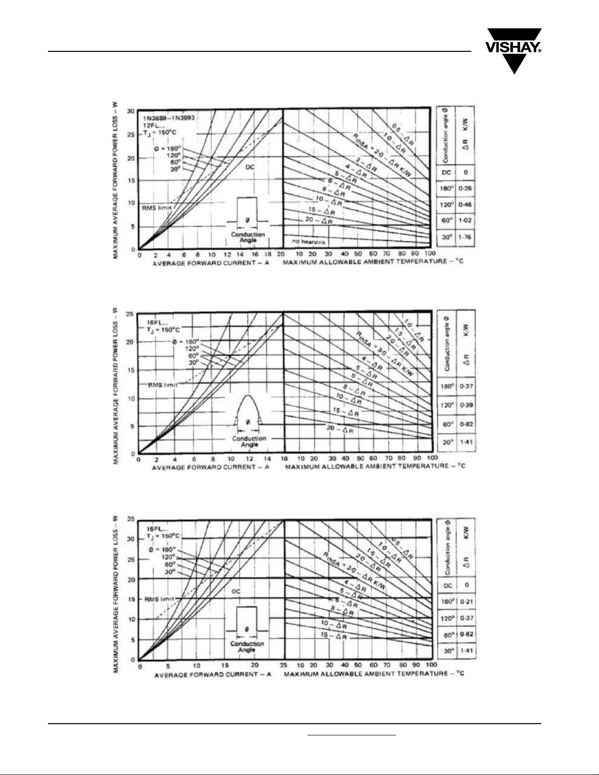
Fig. 1 - Average Forward Current vs.
Maximum Allowable Case Temperature,
1N3879 and 6FL Series
Fig. 2 - Average Forward Current vs.
Maximum Allowable Case Temperature,
1N3889 and 12FL Series
www.vishay.com For technical questions, contact: ind-modules@vishay.com
4 Revision: 26-Sep-08
Fig. 4 - Reverse Recovery Time Test Waveform
Fig. 3 - Average Forward Current vs.
Maximum Allowable Case Temperature, 16FL Series
Document Number: 93138
Page 6

1N3879(R), 1N3889(R), 6/12/16FL(R) Series
Fast Recovery Diodes
Vishay High Power Products
(Stud Version), 6/12/16 A
Fig. 5 - Current Rating Nomogram (Sinusoidal Waveforms), 1N3879 and 6FL Series
Fig. 6 - Current Rating Nomogram (Rectangular Waveforms), 1N3879 and 6FL Series
Fig. 7 - Current Rating Nomogram (Sinusoidal Waveforms), 1N3889 and 12FL Series
Document Number: 93138 For technical questions, contact: ind-modules@vishay.com
Revision: 26-Sep-08 5
www.vishay.com
Page 7
1N3879(R), 1N3889(R), 6/12/16FL(R) Series
Vishay High Power Products
Fig. 8 - Current Rating Nomogram (Rectangular Waveforms), 1N3889 and 12FL Series
Fast Recovery Diodes
(Stud Version), 6/12/16 A
Fig. 9 - Current Rating Nomogram (Sinusoidal Waveforms), 16FL Series
Fig. 10 - Current Rating Nomogram (Rectangular Waveforms), 16FL Series
www.vishay.com For technical questions, contact: ind-modules@vishay.com
6 Revision: 26-Sep-08
Document Number: 93138
Page 8

1N3879(R), 1N3889(R), 6/12/16FL(R) Series
Fast Recovery Diodes
(Stud Version), 6/12/16 A
Fig. 11 - Maximum Forward Voltage vs. Forward Current,
1N3879 and 6FL Series
Vishay High Power Products
Fig. 14 - Maximum High Level Forward Power Loss vs.
Average Forward Current,
1N3889 and 12FL Series
Fig. 12 - Maximum High Level Forward Power Loss vs.
Average Forward Current,
1N3879 and 6FL Series
Fig. 13 - Maximum Forward Voltage vs. Forward Current,
1N3889 and 12FL Series
Document Number: 93138 For technical questions, contact: ind-modules@vishay.com
Revision: 26-Sep-08 7
Fig. 15 - Maximum Forward Voltage vs. Forward Current,
16FL Series
Fig. 16 - Maximum High Level Forward Power Loss vs.
Average Forward Current,
16FL Series
www.vishay.com
Page 9
1N3879(R), 1N3889(R), 6/12/16FL(R) Series
Vishay High Power Products
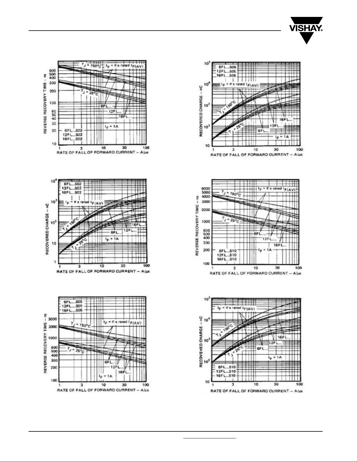
Fig. 17a - Typical Reverse Recovery Time vs.
Rate of Fall of Forward Current, All Series ...S02
Fast Recovery Diodes
(Stud Version), 6/12/16 A
Fig. 18b - Typical Recovered Charge vs.
Rate of Fall of Forward Current, All Series ...S05
Fig. 17b - Typical Recovered Charge vs.
Rate of Fall of Forward Current, All Series ...S02
Fig. 18a - Typical Reverse Recovery Time vs.
Rate of Fall of Forward Current, All Series ...S05
www.vishay.com For technical questions, contact: ind-modules@vishay.com
8 Revision: 26-Sep-08
Fig. 19a - Typical Reverse Recovery Time vs.
Rate of Fall of Forward Current, All Series ...S10
Fig. 19b - Typical Recovered Charge vs.
Rate of Fall of Forward Current, All Series ...S10
Document Number: 93138
Page 10

1N3879(R), 1N3889(R), 6/12/16FL(R) Series
Fast Recovery Diodes
(Stud Version), 6/12/16 A
Fig. 20 - Maximum Non-Repetitive Surge Current vs.
Number of Current Pulses, 1N3879 Series
Vishay High Power Products
Fig. 22 - Maximum Non-Repetitive Surge Current vs.
Number of Current Pulses, 1N3889 and 12FL Series
Fig. 21 - Maximum Non-Repetitive Surge Current vs.
Number of Current Pulses, 6FL Series
Fig. 24 - Maximum Transient Thermal Impedance,
Junction to Case vs. Pulse Duration, All Series
Document Number: 93138 For technical questions, contact: ind-modules@vishay.com
Revision: 26-Sep-08 9
Fig. 23 - Maximum Non-Repetitive Surge Current vs.
Number of Current Pulses, 16FL Series
www.vishay.com
Page 11

1N3879(R), 1N3889(R), 6/12/16FL(R) Series
Vishay High Power Products
ORDERING INFORMATION TABLE
Device code
16 F L R 60 M S02
1 - Current code I
2 - F = Diode
3 - Omit = Standard recovery diode
L = Only for fast diode
4 - Omit = Stud forward polarity
R = Stud reverse polarity
5
- Voltage code x 10 = V
- Outlines:
6
Omit = Stud base UNF thread
M = Stud base metric thread
7
-trr code only for fast diode (see Recovery Characteristics table)
Fast Recovery Diodes
(Stud Version), 6/12/16 A
67
51324
= Exact current rating
(AVG)
(see Voltage Ratings table)
RRM
LINKS TO RELATED DOCUMENTS
Dimensions http://www.vishay.com/doc?95311
www.vishay.com For technical questions, contact: ind-modules@vishay.com
10 Revision: 26-Sep-08
Document Number: 93138
Page 12

Legal Disclaimer Notice
Vishay
Disclaimer
All product specifications and data are subject to change without notice.
Vishay Intertechnology, Inc., its affiliates, agents, and employees, and all persons acting on its or their behalf
(collectively, “Vishay”), disclaim any and all liability for any errors, inaccuracies or incompleteness contained herein
or in any other disclosure relating to any product.
Vishay disclaims any and all liability arising out of the use or application of any product described herein or of any
information provided herein to the maximum extent permitted by law. The product specifications do not expand or
otherwise modify Vishay’s terms and conditions of purchase, including but not limited to the warranty expressed
therein, which apply to these products.
No license, express or implied, by estoppel or otherwise, to any intellectual property rights is granted by this
document or by any conduct of Vishay.
The products shown herein are not designed for use in medical, life-saving, or life-sustaining applications unless
otherwise expressly indicated. Customers using or selling Vishay products not expressly indicated for use in such
applications do so entirely at their own risk and agree to fully indemnify Vishay for any damages arising or resulting
from such use or sale. Please contact authorized Vishay personnel to obtain written terms and conditions regarding
products designed for such applications.
Product names and markings noted herein may be trademarks of their respective owners.
Document Number: 91000 www.vishay.com
Revision: 18-Jul-08 1
 Loading...