

Page 1

6121 Baker Road,
Suite 108
Minnetonka, MN 55345
www.chtechnology.com
Phone (952) 933-6190
Fax (952) 933-6223
1-800-274-4284
Thank you for downloading this document from C&H Technology, Inc.
Please contact the C&H Technology team for the following questions -
Technical
Application
Assembly
Availability
Pricing
Phone – 1-800-274-4284
E-Mail – sales@chtechnology.com
www.chtechnology.com - SPECIALISTS IN POWER ELECTRONIC COMPONENTS AND ASSEMBLIES - www.chtechnology.com
Page 2
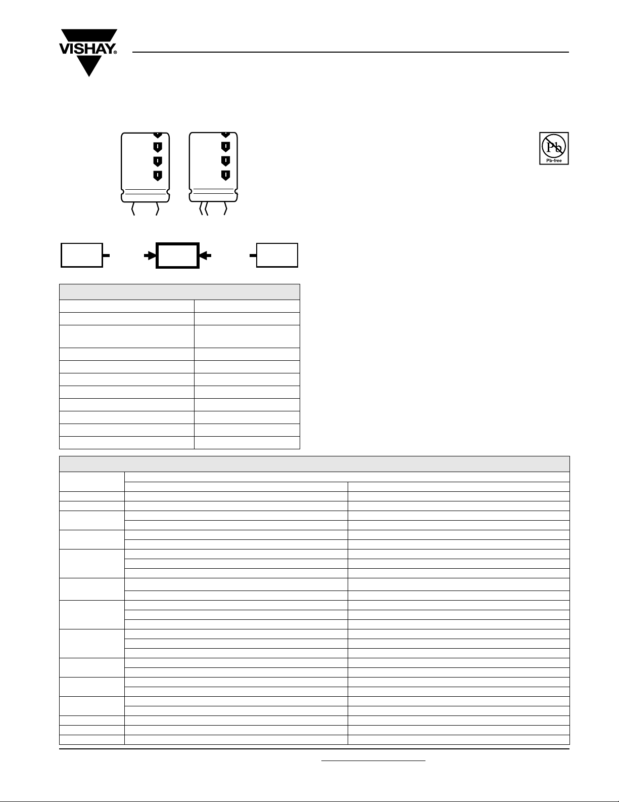
Aluminum Capacitors
Power High Ripple Current Snap-In
Fig. 1 Component outlines
057
PSM-SI
smaller
dimensions
198
PHR-SI
QUICK REFERENCE DATA
DESCRIPTION VALUE
Nominal case size (Ø D x L in mm) 22 x 25 to 35 x 60
Rated capacitance range
(E6/E12 series), C
Tolerance on C
Rated voltage range, U
Category temperature range - 25 to + 85 °C
Endurance test at 85 °C 7000 hours
Useful life at 85 °C 15000 hours
Shelf life at 0 V, 85 °C 1000 hours
Based on sectional specification IEC 60384-4/EN130 300
Climatic category IEC 60068 25/085/56
R
R
R
longer life
higher ripple
56 to 680 µF
± 20 %
400 and 450 V
157
PUM-SI
198 PHR-SI
Vishay BCcomponents
FEATURES
• Polarized aluminum electrolytic capacitors,
non-solid electrolyte
• Large types, miniaturized dimensions,
cylindrical aluminum case, insulated with a blue
sleeve
• Very high ripple current capability
• Keyed polarity version available
• High reliability
APPLICATIONS
• Motor control and industrial systems
• Smoothing and filtering
• Standard and switched mode power supplies
• Energy storage in pulse systems
MARKING
The capacitors are marked (where possible) with the
following information:
• Rated capacitance (in µF)
• Tolerance code on rated capacitance, code letter in
accordance with IEC 60062 (M for ± 20 %)
• Rated voltage (in V)
• Date code (YYMM)
• Name of manufacturer
• Code for factory of origin
• ‘-’ sign to identify the negative terminal, visible from the top
and side of the capacitor
• Code number
• Climatic category in accordance with IEC 60068
RoHS
COMPLIANT
SELECTION CHART FOR CR, UR AND RELEVANT NOMINAL CASE SIZES (Ø D x L in mm)
(V)
C
R
(µF)
56 22 x 25 22 x 25
68 22 x 25 22 x 30
82
100
120
150
180
220
270
330
390
470 35 x 45 35 x 50
560 35 x 50 35 x 60
680 35 x 60 35 x 60
Document Number: 28339 For technical questions, contact: aluminumcaps2@vishay.com
Revision: 08-Aug-08 49
400 450
-22x30
-25x25
22 x 30 22 x 35
-25x30
22 x 35 22 x 40
25 x 30 25 x 30
-30x25
22 x 40 25 x 40
25 x 35 30 x 30
25 x 40 25 x 40
30 x 30 30 x 35
35 x 25 35 x 25
25 x 45 25 x 50
30 x 35 30 x 40
35 x 30 35 x 30
30 x 40 30 x 45
35 x 30 35 x 35
30 x 45 30 x 50
35 x 35 35 x 40
30 x 50 35 x 45
35 x 40 -
U
R
www.vishay.com
Page 3
198 PHR-SI
n
y
Vishay BCcomponents
Aluminum Capacitors
Power High Ripple Current Snap-In
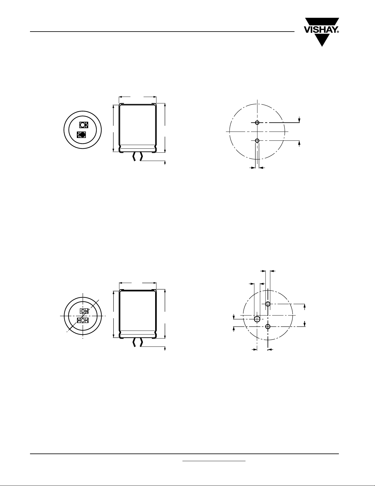
DIMENSIONS in millimeters AND AVAILABLE FORMS
TWO TERMINAL SNAP-IN
Ø D
+ TERMINAL
- TERMINAL
Bottom view
The minus terminal can be marked with a black dot or with a
imprinted ‘-’ sign.
Fig. 2 Two terminal snap-in
L
5.8
L + 2
max.
+ 0
- 1
10
± 0.1
Ø 2 ± 0.1 (2 x)
Fig. 3 Mounting hole diagram
THREE TERMINAL SNAP-IN
Ø D
+ TERMINAL
- TERMINAL
minus pole
marking
L
Bottom view
L + 2
max.
4 ± 0.5
The negative terminal has TWO pins which are BOTH electricall
connected.
Fig. 4 Three terminal snap-in
Ø 2 ± 0.1 (2 x)
Ø 2.5 ± 0.1
10
3.3
± 0.1
4.75 ± 0.1
± 0.1
The 10 mm spacing of the 2 pin snap-in is used as the base layout
and a third hole is added.
The third hole is closer to the negative primary hole so that
polarization is always maintained, together with added mechanical
stability.
Fig. 5 Mounting hole diagram
www.vishay.com For technical questions, contact: aluminumcaps2@vishay.com
Document Number: 28339
50 Revision: 08-Aug-08
Page 4

198 PHR-SI
Aluminum Capacitors
Vishay BCcomponents
Power High Ripple Current Snap-In
Tab l e 1
DIMENSIONS in millimeters, MASS AND PACKAGING QUANTITIES
NOMINAL
CASE SIZE
Ø D x L
(mm)
22 x 25 23 27 ≈ 12 100 260 x 250 x 39
22 x 30 23 32 ≈ 16 100 260 x 250 x 44
22 x 35 23 37 ≈ 20 100 260 x 250 x 49
22 x 40 23 42 ≈ 23 100 260 x 250 x 54
25 x 25 26 27 ≈ 20 100 290 x 280 x 39
25 x 30 26 32 ≈ 22 100 290 x 280 x 44
25 x 35 26 37 ≈ 24 100 290 x 280 x 49
25 x 40 26 42 ≈ 27 100 290 x 280 x 54
25 x 45 26 47 ≈ 32 100 290 x 280 x 59
25 x 50 26 52 ≈ 38 100 290 x 280 x 64
30 x 25 31 27 ≈ 25 100 340 x 330 x 39
30 x 30 31 32 ≈ 30 100 340 x 330 x 44
30 x 35 31 37 ≈ 35 100 340 x 330 x 49
30 x 40 31 42 ≈ 40 100 340 x 330 x 54
30 x 45 31 47 ≈ 45 100 340 x 330 x 59
30 x 50 31 52 ≈ 50 100 340 x 330 x 64
35 x 25 36 27 ≈ 33 50 390 x 198 x 39
35 x 30 36 32 ≈ 40 50 390 x 198 x 44
35 x 35 36 37 ≈ 48 50 390 x 198 x 49
35 x 40 36 42 ≈ 55 50 390 x 198 x 54
35 x 45 36 47 ≈ 63 50 390 x 198 x 59
35 x 50 36 52 ≈ 72 50 390 x 198 x 64
35 x 60 36 62 ≈ 87 50 390 x 198 x 74
Ø D
max.
L
max.
MASS
(g)
PACKAGING QUANTITIES
(units per box)
CARDBOARD BOX DIMENSIONS
L x W x H
ELECTRICAL DATA
SYMBOL DESCRIPTION
C
R
I
R
I
L1
I
L5
ESR typ./max. equivalent series resistance at 100 Hz
Z typ./max. impedance at 10 kHz
Note
Unless otherwise specified, all electrical values in Table 2 apply at
T
= 20 °C, P = 86 to 106 kPa, RH = 45 to 75 %
amb
Document Number: 28339 For technical questions, contact: aluminumcaps2@vishay.com
Revision: 08-Aug-08 51
rated capacitance at 100 Hz
rated RMS ripple current at 100 Hz, 85 °C
max. leakage current after 1 minute at U
max. leakage current after 5 minutes at U
R
R
ORDERING EXAMPLE
Electrolytic capacitor 198 PHR-SI
470µF/450V; ± 20 %
Nominal case size: Ø 35 x 50 mm
2-terminal snap-in:
Ordering code: MAL2198 57471E3
Former 12NC: 2222198 57471
3-terminal snap-in:
Ordering code: MAL2198 77471E3
Former 12NC: 2222198 77471
www.vishay.com
Page 5

198 PHR-SI
Vishay BCcomponents
Aluminum Capacitors
Power High Ripple Current Snap-In
Tab l e 2
ELECTRICAL DATA AND ORDERING INFORMATION
U
(V)
400
400
450
C
R
100 Hz
(µF)
100 22 x 30 1.00 244 84 520 956 297 610 56101E3
120 22 x 35 1.14 292 100 433 796 247 450 46121E3 26121E3
120 25 x 30 1.14 292 100 438 796 252 450 36121E3 16121E3
150 22 x 40 1.33 364 124 348 637 199 363 66151E3 86151E3
150 25 x 35 1.33 364 124 351 637 202 363 36151E3 16151E3
180 25 x 40 1.51 436 148 293 531 169 295 36181E3 16181E3
180 30 x 30 1.49 436 148 305 531 180 295 66181E3 86181E3
180 35 x 25 1.56 436 148 327 531 200 295 26181E3 76181E3
220 25 x 45 1.75 532 180 241 434 139 280 36221E3 90008E3
220 30 x 35 1.56 532 180 250 434 147 280 26221E3 76221E3
220 35 x 30 1.81 532 180 259 434 155 280 16221E3 86221E3
270 30 x 40 1.95 652 220 205 354 121 263 36271E3 16271E3
270 35 x 30 1.93 652 220 222 354 137 263 66271E3 86271E3
330 30 x 45 2.22 796 268 169 290 101 210
330 35 x 35 2.18 796 268 181 290 112 210
390 30 x 50 2.50 940 316 145 245 86 175 36391E3 16391E3
390 35 x 40 2.44 940 316 154 245 95 175 66391E3 86391E3
470 35 x 45 2.72 1132 380 129 203 80 153
560 35 x 50 3.03 1348 452 110 171 70 133 46561E3 26561E3
680 35 x 60 3.53 1636 548 91 140 57 110 46681E3 26681E3
100 22 x 35 1.02 274 94 485 956 270 525 47101E3 27101E3
100 25 x 30 1.05 274 94 491 956 274 525 57101E3 77101E3
120 22 x 40 1.14 328 112 406 796 225 443 47121E3 27121E3
120 25 x 30 1.13 328 112 415 796 233 443 57121E3 77121E3
120 30 x 25 1.16 328 112 431 796 248 443 67121E3 87121E3
150 25 x 40 1.36 409 139 328 637 184 353 47151E3 27151E3
150 30 x 30 1.36 409 139 340 637 194 353 57151E3 77151E3
180 25 x 40 1.47 490 166 277 531 157 303 47181E3 27181E3
180 30 x 35 1.54 490 166 282 531 161 303 57181E3 77181E3
180 35 x 25 1.46 490 166 316 531 191 303 67181E3 87181E3
220 25 x 50 1.71 598 202 226 434 127 263 47221E3 27221E3
220 30 x 40 1.75 598 202 232 434 133 263 57221E3 77221E3
220 35 x 30 1.72 598 202 248 434 148 263 67221E3 87221E3
270 30 x 45 1.98 733 247 191 354 110 225 47271E3
270 35 x 35 1.96 733 247 202 354 120 225
330 30 x 50 2.22 895 301 158 290 91 195 47331E3 27331E3
330 35 x 40 2.22 895 301 167 290 100 195 57331E3 77331E3
390 35 x 45 2.46 1057 355 142 245 85 170 57391E3 77391E3
470 35 x 50 2.73 1273 427 120 203 73 145
560 35 x 60 3.10 1516 508 100 171 60 120 57561E3
680 35 x 60 3.30 1840 616 88 140 55 110 57681E3 77681E3
NOMINAL
R
CASE SIZE
Ø D x L
(mm)
56 22 x 25 0.72 138 49 918 1706 521 1085 56569E3 76569E3
68 22 x 25 0.79 167 59 762 1405 434 905 56689E3
56 22 x 25 0.71 155 54.4 865 1706 479 940 57569E3 77569E3
68 22 x 30 0.82 188 65.2 709 1405 392 765 57689E3 77689E3
82 22 x 30 0.89 225 77.8 592 1165 329 645 47829E3 27829E3
82 25 x 25 0.91 225 77.8 604 1165 339 645 57829E3 77829E3
I
R
100 Hz
85 °C
(A)
I
L1
1min
(µA)
I
L5
5min
(µA)
TYP.
ESR
100 Hz
(mΩ)
MAX.
ESR
100 Hz
(mΩ)
TYP. Z
10 kHz
(mΩ)
MAX. Z
10 kHz
(mΩ)
ORDERING CODE
MAL2198.......
2-TERM. 3-TERM.
76689E3
76101E3
36331E3
66331E3
36471E3 16471E3
57271E3
57471E3
16331E3
86331E3
27271E3
77271E3
77471E3
77561E3
CUSTOMIZED PRODUCTS
If you are unable to find the capacitor you require, please contact your local Vishay BCcomponents sales organization; we are
able to design and manufacture customized capacitors to meet your specific requirements.
www.vishay.com For technical questions, contact: aluminumcaps2@vishay.com
52 Revision: 08-Aug-08
Document Number: 28339
Page 6

198 PHR-SI
Aluminum Capacitors
Vishay BCcomponents
Power High Ripple Current Snap-In
ADDITIONAL ELECTRICAL DATA
PARAMETER CONDITIONS VALUE
Voltage
Surge voltage ≥ 400 V versions U
Reverse voltage ≤ 1V
Current
Leakage current
After 1 minute at U
After 5 minutes at U
R
R
Inductance
Equivalent series inductance (ESL) All case sizes
Tab l e 3
MULTIPLIER OF RIPPLE CURRENT (IR) AS A FUNCTION OF FREQUENCY
FREQUENCY (Hz)
50 0.86
100 1.00
300 1.17
600 1.24
1000 1.29
≥ 10 000 1.40
=1.1xU
s
R
IL1≤ 0.006 CRxUR+4µA
IL5≤ 0.002 CRxUR+4µA
typ. 19 nH
max. 25 nH
MULTIPLIER
I
R
RIPPLE CURRENT AND USEFUL LIFE
1.6
I
forced
Curve 1: case
R
free
I
R
1.5
1.4
1.3
(1)
(2)
(3)
(4)
Ø DxL=35x25mm
Curve 2: case
1.2
Ø DxL=22x25mm
Curve 3: case
Ø DxL=35x50mm
1.1
Curve 4: case
Ø D x L = 22 x 40 mm
1.0
0 0.5 1 1.5 2 2.5 3 3.5 4 4.5 5
air velocity (m/s)
Fig. 6 Multiplier of ripple current (IR) as a function of air-flow
MAXIMUM RIPPLE CURRENT MULTIPLIER
PARAMETER CONDITION MAXIMUM RIPPLE CURRENT MULTIPLIER VALUE
Ambient temperature (T
Operating frequency (f) 300 Hz from frequency table; see Table 1.17
Air-flow 2 m/s from air-flow; see Fig.6 1.35
Note
Calculation example for case Ø D x L = 35 x 25 mm
Therefore the maximum ripple current multiplier at 70 °C, 300 Hz and 2 m/s air-flow = 1.57 x 1.17 x 1.35 = 2.48.
Document Number: 28339 For technical questions, contact: aluminumcaps2@vishay.com
Revision: 08-Aug-08 53
)70°C from nomogram; see Fig.7 1.57
amb
www.vishay.com
Page 7

198 PHR-SI
Vishay BCcomponents
IA= actual ripple current at 100 Hz
= rated ripple current at 100 Hz and 85 °C
I
R
(1)
Useful life at 85 °C and UR applied:
15 000 hours
Fig. 7 Multiplier of useful life as a function of ambient temperature and ripple current load
Aluminum Capacitors
Power High Ripple Current Snap-In
2.4
2.3
I
A
I
R
2.2
2.1
2.0
1.9
1.8
1.7
1.6
1
1.2
life multiplier
1.5
1.5
2
2.5
1.4
3
4
1.3
5
8
1.2
10
15
1.1
1.0
0.8
60
20
30
45
0.5
0.0
40 50 60 70 80 90
MGA 453
(1 )
T
(°C)
amb
Tab l e 4
TEST PROCEDURES AND REQUIREMENTS
TEST
NAME OF TEST REFERENCE
Endurance IEC 60384-4/
EN130300
subclause 4.13
Useful life CECC 30 301
Shelf life
(storage at
high temperature)
www.vishay.com For technical questions, contact: aluminumcaps2@vishay.com
54 Revision: 08-Aug-08
subclause 1.8.1
IEC 60384-4/
EN130300
subclause 4.17
T
=85°C; UR applied;
amb
7000 hours
T
=85°C; UR and IR applied;
amb
15 000 hours
T
=85°C; no voltage applied;
amb
1000 hours
after test: U
24 to 48 hours before measurement
PROCEDURE
(quick reference)
to be applied for 30 minutes,
R
REQUIREMENTS
ΔC/C: ± 10 %
ESR ≤ 2 x spec. limit
IL5 ≤ spec. limit
ΔC/C: ± 30 %
ESR ≤ 3 x spec. limit
IL5 ≤ spec. limit
ΔC/C: ± 15 %
ESR ≤ 2 x spec. limit
IL5 ≤ 2 x spec. limit
Document Number: 28339
Page 8

Legal Disclaimer Notice
Vishay
Disclaimer
All product specifications and data are subject to change without notice.
Vishay Intertechnology, Inc., its affiliates, agents, and employees, and all persons acting on its or their behalf
(collectively, “Vishay”), disclaim any and all liability for any errors, inaccuracies or incompleteness contained herein
or in any other disclosure relating to any product.
Vishay disclaims any and all liability arising out of the use or application of any product described herein or of any
information provided herein to the maximum extent permitted by law. The product specifications do not expand or
otherwise modify Vishay’s terms and conditions of purchase, including but not limited to the warranty expressed
therein, which apply to these products.
No license, express or implied, by estoppel or otherwise, to any intellectual property rights is granted by this
document or by any conduct of Vishay.
The products shown herein are not designed for use in medical, life-saving, or life-sustaining applications unless
otherwise expressly indicated. Customers using or selling Vishay products not expressly indicated for use in such
applications do so entirely at their own risk and agree to fully indemnify Vishay for any damages arising or resulting
from such use or sale. Please contact authorized Vishay personnel to obtain written terms and conditions regarding
products designed for such applications.
Product names and markings noted herein may be trademarks of their respective owners.
Document Number: 91000 www.vishay.com
Revision: 18-Jul-08 1
 Loading...