

Page 1

6121 Baker Road,
Suite 108
Minnetonka, MN 55345
www.chtechnology.com
Phone (952) 933-6190
Fax (952) 933-6223
1-800-274-4284
Thank you for downloading this document from C&H Technology, Inc.
Please contact the C&H Technology team for the following questions -
Technical
Application
Assembly
Availability
Pricing
Phone – 1-800-274-4284
E-Mail – sales@chtechnology.com
www.chtechnology.com - SPECIALISTS IN POWER ELECTRONIC COMPONENTS AND ASSEMBLIES - www.chtechnology.com
Page 2
Bulletin PD-21149 06/06
Document Number: 94460
www.vishay.com
1
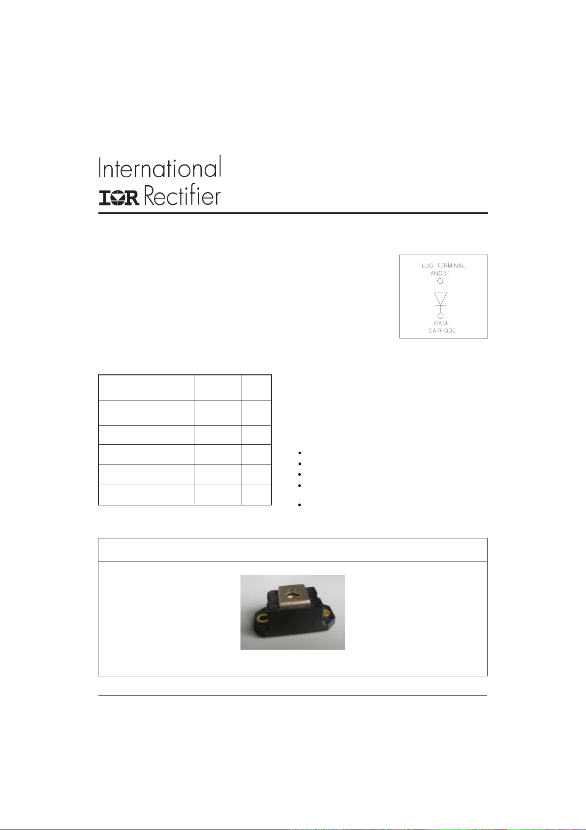
182NQ030PbF
SCHOTTKY RECTIFIER
Major Ratings and Characteristics
Characteristics Values Units
I
Rectangular 180 A
F(AV)
waveform
V
RRM
I
@ tp = 5 μs sine 20000 A
FSM
VF@ 180Apk, TJ=125°C 0.45 V
TJrange - 55 to 15 0 °C
30 V
180Amp
Description/ Features
The 182NQ.. high current Schottky rectifier module series has
been optimized for low reverse leakage at high temperature.
The proprietary barrier technology allows for reliable operation
up to 150 °C junction temperature. Typical applications are in
high current switching power supplies, plating power supplies,
UPS systems, converters, free-wheeling diodes, welding, and
reverse battery protection.
150 °C TJ operation
Low forward voltage drop
High frequency operation
Guard ring for enhanced ruggedness and long term
reliability
Lead-Free
Case Styles
HALF-PAK (D-67)
Page 3
182NQ030PbF
Document Number: 94460
www.vishay.com
2
Bulletin PD-21149 06/06
Voltage Ratings
Part number 182NQ030PbF
V
Max. DC Reverse Voltage (V)
R
V
Max. Working Peak Reverse Voltage (V)
RWM
30
Absolute Maximum Ratings
Parameters 182NQ Units Conditions
I
Max. Average Forward Current 180 A 50% duty cycle @ TC = 108 °C, rectangular wave form
F(AV)
* See Fig. 5
I
Max. Peak One Cycle Non-Repetitive 20000 5μs Sine or 3μs Rect. pulse
FSM
Surge Current * See Fig. 7 2500 10ms Sine or 6ms Rect. pulse
EASNon-Repetitive Avalanche Energy 162 mJ T
A
= 25 °C, I
J
AS
= 18 Amps, L = 1 mH
Following any rated
load condition and with
rated V
RRM
applied
IARRepetitive Avalanche Current 36 A Current decaying linearly to zero in 1 μsec
Frequency limited by TJ max. VA = 1.5 x VR typical
Electrical Specifications
Parameters 182NQ Units Conditions
VFMMax. Forward Voltage Drop 0.59 V @ 180A
* See Fig. 1 (1) 0.8 V @ 360A
0.45 V @ 180A
0.65 V @ 360A
IRMMax. Reverse Leakage Current 15 mA TJ = 25 °C
* See Fig. 2 840 mA TJ = 125 °C
CTMax. Junction Capacitance 7700 pF VR = 5VDC (test signal range 100Khz to 1Mhz) 25°C
LSTypical Series Inductance 6.0 nH From top of terminal hole to mounting plane
dv/dt Max. Voltage Rate of Change 10000 V/ μs
(Rated VR)
TJ = 25 °C
TJ = 125 °C
VR = rated V
R
(1) Pulse Width = 500μs
Thermal-Mechanical Specifications
Parameters 182NQ Units Conditions
TJMax. Junction Temperature Range -55 to 150 °C
T
Max. Storage Temperature Range -55 to 150 °C
stg
R
Max. Thermal Resistance Junction 0.28 °C/W DC operation * See Fig. 4
thJC
to Case
R
Typical Thermal Resistance, Case to 0.05 °C/W Mounting surface , smooth and greased
thCS
Heatsink
wt Approximate Weight 30 (1.06) g (oz.)
T Mounting Torque Min. 3 (26.5) Non-lubricated threads
Max. 4 (35.4)
Terminal Torque Min. 3.4 (30)
Max. 5 (44.2)
Case Style HALF PAK Module
Nm
(Ibf-in)
Page 4

182NQ030PbF
5
Document Number: 94460
www.vishay.com
3
Bulletin PD-21149 06/06
1000
100
(A)
F
10
Instantaneous Forward Current - I
Tj = 150°C
Tj = 125°C
Tj = 25°C
1
0.0 0.2 0.4 0.6 0.8 1.0 1.2 1.4 1.6
Forward Voltage Drop - VFM (V)
Fig. 1 - Max. Forward Voltage Drop Characteristics
1
10000
T = 150°C
1000
(mA)
R
Reverse Current - I
J
125°C
100
10
1
.1
.01
100°C
75°C
50°C
25°C
0 5 10 15 20 25 30
Reverse Voltage - V R (V)
Fig. 2 - Typical Values Of Reverse Current
Vs. Reverse Voltage
10000
(pF)
T
T = 25°C
J
Junction Capacitance - C
1000
0 5 10 15 20 25 30 3
Reverse Voltage - V R (V)
Fig. 3 - Typical Junction Capacitance
Vs. Reverse Voltage
D = 0.75
0.1
0.01
D = 0.50
D = 0.33
D = 0.25
D = 0.20
Single Pulse
(Thermal Resistance)
(°C/W)
thJC
Thermal Impedance Z
0.001
1E-05 1E-04 1E-03 1E-02 1E-01 1E+00 1E+01
t1, Rectangular Pulse Duration (Seconds)
Fig. 4 - Max. Thermal Impedance Z
Characteristics
thJC
Page 5

182NQ030PbF
Document Number: 94460
www.vishay.com
4
Bulletin PD-21149 06/06
160
150
140
130
120
110
100
90
Square wave (D=0.50)
80% rated Vr applied
80
70
Allowable Case Temperature (°C)
see note (2)
60
0 50 100 150 200 250 300 350
Average Forward Current - I
Fig. 5 - Max. Allowable Case Temperature
Vs. Average Forward Current
100000
(A)
FSM
10000
1000
DC
F (AV)
(A)
180
D = 0.20
160
D = 0.25
D = 0.33
140
D = 0.50
D = 0.75
120
100
RMS limit
80
DC
60
40
Average Power Loss (Watts)
20
0
0 50 100 150 200 250 300 350
Average Forward Current - I
Fig. 6 - Forward Power Loss Characteristics
F (AV)
(A)
DUT
CURRENT
MONITOR
(2) Formula used: TC = TJ - (Pd + Pd
Pd = Forward Power Loss = I
Pd
= Inverse Power Loss = VR1 x IR (1 - D); IR @ V
REV
F(AV)
Non-Repetitive Surge Current - I
100
10 100 1000 10000
Square Wave Pulse Duration - t
Fig. 7 - Max. Non-Repetitive Surge Current
L
IR FP 460
Rg = 25 o h m
Fig. 8 - Unclamped Inductive Test Circuit
) x R
thJC
x VFM @ (I
;
/ D) (see Fig. 6);
F(AV)
R1
= rated V
R
REV
(microsec)
p
HIGH-SP E E D
SWI TC H
FREE-WHEEL
DIODE
40HF L 4 0S02
Vd = 25 Volt
+
Page 6

Outline Table
Document Number: 94460
www.vishay.com
5
182NQ030PbF
Bulletin PD-21149 06/06
Ordering Information Table
Device Code
Dimensions in millimeters and (inches)
HALF-PAK (D-67)
18 2 N Q 030 P b F
5
24
1
1 - Average Current Rating (x 10)
2 - Product Silicon Identification
3 - N = NOt Isolated
4 - Q = Schottky Rectifier Diode
5 - Voltage Rating (030 = 30V)
6 - Lead-Free
3
6
Page 7

182NQ030PbF
Document Number: 94460
www.vishay.com
6
Bulletin PD-21149 06/06
This product has been designed and qualified for Industrial Level and Lead-Free.
Data and specifications subject to change without notice.
Qualification Standards can be found on IR's Web site.
IR WORLD HEADQUARTERS: 233 Kansas St., El Segundo, California 90245, USA Tel: (310) 252-7105
TAC Fax: (310) 252-7309
06/06
 Loading...