

Page 1

6121 Baker Road,
Suite 108
Minnetonka, MN 55345
www.chtechnology.com
Phone (952) 933-6190
Fax (952) 933-6223
1-800-274-4284
Thank you for downloading this document from C&H Technology, Inc.
Please contact the C&H Technology team for the following questions -
Technical
Application
Assembly
Availability
Pricing
Phone – 1-800-274-4284
E-Mail – sales@chtechnology.com
www.chtechnology.com - SPECIALISTS IN POWER ELECTRONIC COMPONENTS AND ASSEMBLIES - www.chtechnology.com
Page 2
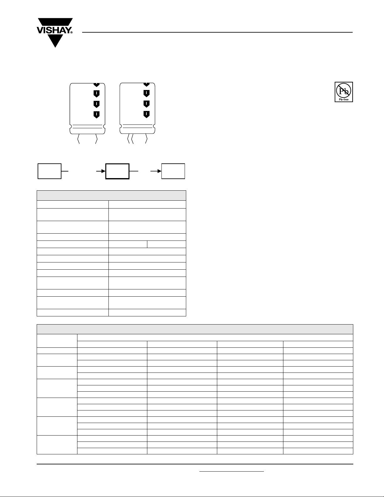
Aluminum Capacitors
Power Ultra Long Life Snap-In
Fig.1 Component outlines
059
PLL-SI
miniaturized
QUICK REFERENCE DATA
DESCRIPTION VALUE
Nominal case size
(Ø D x L in mm)
Rated capacitance range
(E6/E12 series), C
Tolerance on C
Rated voltage range, U
Category temperature range - 25 °C to + 105 °C
Endurance test at 105 °C 2000 hours
Load life at 105 °C 2000 hours
Useful life at 105 °C 5000 hours
Useful life at 40 °C and
applied
1.6 x I
R
Shelf life at 0 V, 105 °C 1000 hours
Based on sectional
specification
Climatic category IEC 60068 25/105/56
R
R
R
159
PUL-SI
200 V, 250 V 400 V, 450 V
85 °C
22 x 25
to 35 x 60
56 µF to 1800 µF
± 20 %
500 000 hours
IEC 60384-4/EN130300
157
PUM-SI
159 PUL-SI
Vishay BCcomponents
FEATURES
• Polarized aluminum electrolytic capacitors,
non-solid electrolyte
• Large types, very small dimensions, cylindrical
aluminum case, insulated with a blue sleeve
• Low ESR, high ripple current capability
• Useful life: 5000 hours at 105 °C
• Keyed polarity snap-in version available
APPLICATIONS
• General purpose, industrial and audio/video systems
• Smoothing and filtering
• Standard and switched mode power supplies
• Energy storage in pulse systems
MARKING
The capacitors are marked (where possible) with the
following information:
• Rated capacitance (in µF)
• Tolerance code on rated capacitance, code letter in
accordance with IEC 60062 (M for ± 20 %)
• Rated voltage (in V)
• Date code (YYMM)
• Name of manufacturer
• Code for factory of origin
• ‘-’ sign to identify the negative terminal, visible from the top
and side of the capacitor
• Code number, all 12 or last 8 digits (2222) 159 xxxxx
• Climatic category in accordance with IEC 60068
RoHS
COMPLIANT
SELECTION CHART FOR CR , UR AND RELEVANT NOMINAL CASE SIZES (Ø D x L in mm)
U
C
R
(µF)
56 - - - 22 x 25
68
82
100
120
150
180
Document Number: 28341 For technical questions, contact: aluminumcaps2@vishay.com
Revision: 14-Oct-08 99
200 250 400 450
- - 22 x 25 22 x 30
---25x25
- - 22 x 30 22 x 35
--25x25-
- - 22 x 35 22 x 40
- - 25 x 30 25 x 30
---30x25
--22x35-
- - 25 x 30 25 x 35
--30x25-
- - 22 x 40 25 x 40
- - 25 x 35 30 x 30
- - 30 x 30 35 x 25
- - 25 x 40 25 x 45
- - 30 x 30 30 x 35
--35x25-
R
(V)
www.vishay.com
Page 3
159 PUL-SI
Vishay BCcomponents
Aluminum Capacitors
Power Ultra Long Life Snap-In
SELECTION CHART FOR CR , UR AND RELEVANT NOMINAL CASE SIZES (Ø D x L in mm)
(V)
C
R
(µF)
200 250 400 450
- 22 x 30 25 x 45 30 x 40
220
- 25 x 25 30 x 35 35 x 30
--35x30-
- 22 x 35 25 x 50 30 x 45
270
- 25 x 30 30 x 40 35 x 35
- 30 x 25 35 x 30 -
22 x 30 22 x 40 30 x 45 30 x 50
330
- 25 x 30 35 x 35 35 x 40
-30x25 - -
390
22 x 35 25 x 35 30 x 50 35 x 45
25 x 30 30 x 30 35 x 40 22 x 40 25 x 40 35 x 45 35 x 50
470
30 x 25 30 x 30 - -
35 x 25
- 25 x 45 - 35 x 60
560
25 x 35 30 x 35 - 30 x 30 35 x 30 - 25 x 45 30 x 40 35 x 60 -
680
30 x 30 35 x 35 - 35 x 25 - - 25 x 50 30 x 45 - -
820
30 x 35 35 x 35 - 35 x 30 35 x 40 - -
1000
1200
30 x 45 35 x 40 - 35 x 35 35 x 45 - 30 x 50 35 x 45 - -
35 x 35 35 x 50 - 1500 35 x 45 - - 1800 35 x 50 - - -
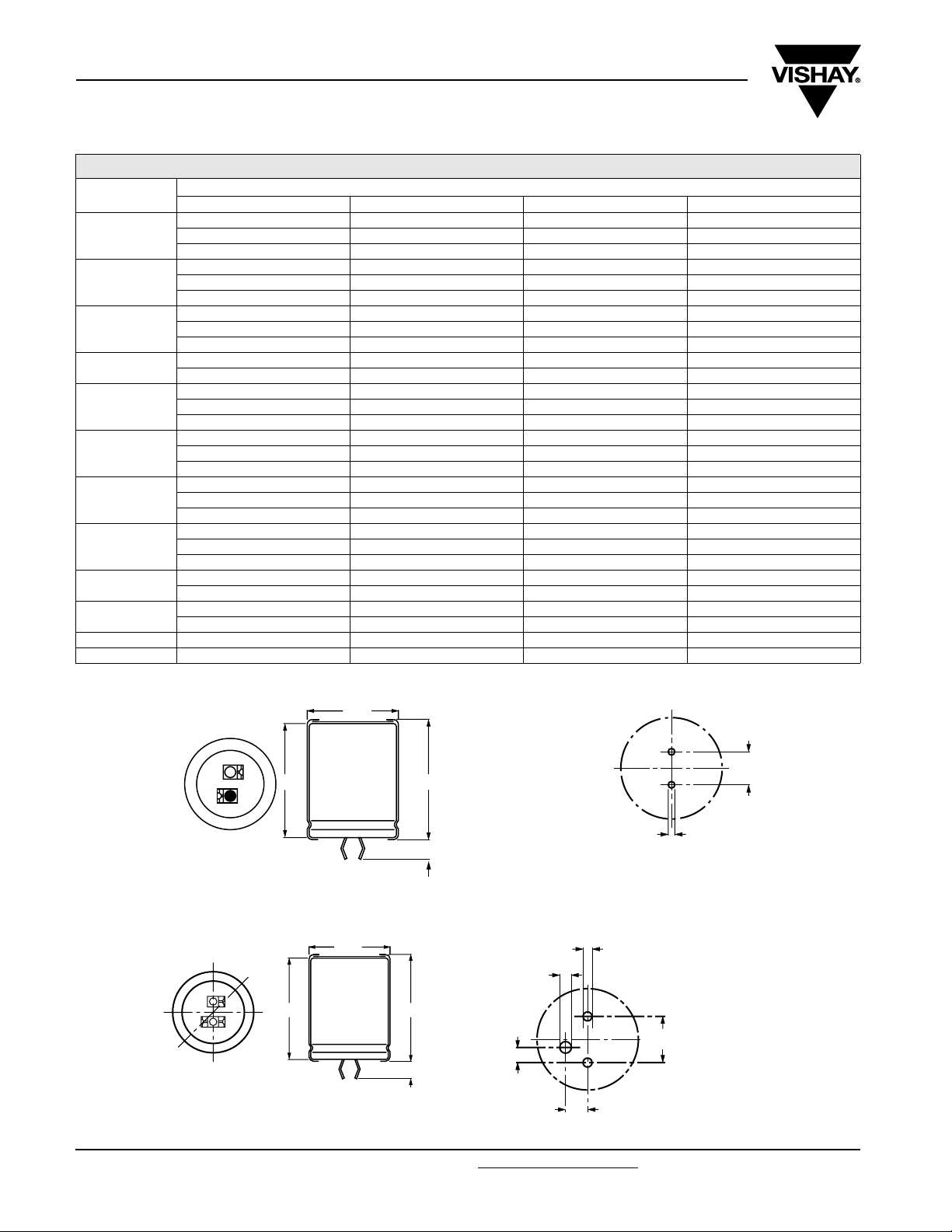
DIMENSIONS in millimeters AND AVAILABLE FORMS
TWO TERMINAL SNAP-IN
Ø D
U
R
+ Terminal
- Terminal
Bottom view
The minus terminal can be marked with a black dot
or with an imprinted ‘-’ sign.
Fig.2 Two terminal snap-in
THREE TERMINAL SNAP-IN
+ Terminal
- Terminal
Minus pole
marking
Bottom view
The negative terminal has TWO pins which are BOTH
electrcally connected
Fig.4 Two terminal snap-in
L
L + 2 max.
+ 0
5.8 mm
- 1
Ø 2 ± 0.1 (2 x)
Fig.3 Mounting hole diagram
Ø
2.5 ± 0.1
Ø
2 ± 0.1 (2 x)
4.75 ± 0.1
The 10 mm spacing of the 2 pin
10
snap-in is used as the base layout
±0.1
and a third hole is added.
The third hole is closer to the
negative primary hole so that
polarization is always maintained,
together with added mechanical
stability.
Ø D
L
L + 2 max.
4 ± 0.5
3.3
± 0.1
Fig.5 Mounting hole diagram
10
±0.1
www.vishay.com For technical questions, contact: aluminumcaps2@vishay.com Document Number: 28341
100 Revision: 14-Oct-08
Page 4

159 PUL-SI
Aluminum Capacitors
Power Ultra Long Life Snap-In
Tab l e 1
DIMENSIONS in millimeters, MASS AND PACKAGING QUANTITIES
NOMINAL
CASE SIZE
Ø D x L
22 x 25 23 27 ≈ 12 100 260 x 250 x 39
22 x 30 23 32 ≈ 16 100 260 x 250 x 44
22 x 35 23 37 ≈ 20 100 260 x 250 x 49
22 x 40 23 42 ≈ 23 100 260 x 250 x 54
25 x 25 26 27 ≈ 20 100 290 x 280 x 39
25 x 30 26 32 ≈ 22 100 290 x 280 x 44
25 x 35 26 37 ≈ 24 100 290 x 280 x 49
25 x 40 26 42 ≈ 27 100 290 x 280 x 54
25 x 45 26 47 ≈ 32 100 290 x 280 x 59
25 x 50 26 52 ≈ 38 100 290 x 280 x 64
30 x 25 31 27 ≈ 25 100 340 x 330 x 39
30 x 30 31 32 ≈ 30 100 340 x 330 x 44
30 x 35 31 37 ≈ 35 100 340 x 330 x 49
30 x 40 31 42 ≈ 40 100 340 x 330 x 54
30 x 45 31 47 ≈ 45 100 340 x 330 x 59
30 x 50 31 52 ≈ 50 100 340 x 330 x 64
35 x 25 36 27 ≈ 33 50 390 x 198 x 39
35 x 30 36 32 ≈ 40 50 390 x 198 x 44
35 x 35 36 37 ≈ 48 50 390 x 198 x 49
35 x 40 36 42 ≈ 55 50 390 x 198 x 54
35 x 45 36 47 ≈ 63 50 390 x 198 x 59
35 x 50 36 52 ≈ 72 50 390 x 198 x 64
35 x 60 36 62 ≈ 84 50 390 x 198 x 74
Ø D
max.
L
max.
MASS
(g)
PACKAGING QUANTITIES
(units per box)
Vishay BCcomponents
CARDBOARD BOX
DIMENSIONS
L x W x H
ELECTRICAL DATA
SYMBOL DESCRIPTION
C
R
I
R
I
L5
ESR
Z typ./max. impedance at 10 kHz
Notes
(1)
ESR at 120 Hz is approximately 0.95 x ESR 100 Hz
• Unless otherwise specified, all electrical values in Table 2 apply
at T
Document Number: 28341 For technical questions, contact: aluminumcaps2@vishay.com
Revision: 14-Oct-08 101
rated capacitance at 100 Hz
rated RMS ripple current at 120 Hz, 105 °C
max. leakage current after 5 min at U
typ./max. equivalent series resistance at 100 Hz
= 20 °C, P = 86 to 106 kPa, RH = 45 to 75 %
amb
R
(1)
ORDERING EXAMPLE
Electrolytic capacitor 159 series
1000 µF/200 V; ± 20 %
Nominal case size: Ø 30 x 45 mm
2-terminal snap-in:
Ordering code: MAL2159 42102E3
Former 12NC: 2222159 42102
3-terminal snap-in:
Ordering code: MAL2159 22102E3
Former 12NC: 2222159 22102
www.vishay.com
Page 5

159 PUL-SI
Vishay BCcomponents
Aluminum Capacitors
Power Ultra Long Life Snap-In
Tab l e 2
ELECTRICAL DATA AND ORDERING INFORMATION
C
U
R
(V)
200
250
Note
(1)
ESR at 120 Hz is approximately 0.95 x ESR 100 Hz
R
100 Hz
(µF)
330 22 x 30 1.08 0.66 450 730 300 500 52331E3 72331E3
390 22 x 35 1.23 0.78 380 610 280 470 42391E3 22391E3
390 25 x 30 1.23 0.78 380 610 280 470 52391E3 72391E3
470 22 x 40 1.37 0.94 300 505 240 400 32471E3 12471E3
470 30 x 25 1.27 0.94 300 505 240 400 52471E3 72471E3
560 25 x 35 1.50 1.12 260 425 235 390 42561E3 22561E3
560 30 x 30 1.52 1.12 260 425 235 390 52561E3 72561E3
680 25 x 45 1.82 1.36 210 350 205 340 42681E3 22681E3
680 30 x 30 1.59 1.36 210 350 205 340 52681E3 72681E3
680 35 x 25 1.44 1.36 210 350 205 340 62681E3 82681E3
820 25 x 50 2.04 1.64 180 290 145 240 32821E3 12821E3
820 30 x 35 1.83 1.64 180 290 145 240 42821E3 22821E3
820 35 x 30 1.77 1.64 180 290 145 240 52821E3 72821E3
1000 30 x 45 2.23 2.00 150 235 135 225 42102E3 22102E3
1000 35 x 35 2.04 2.00 150 235 135 225 52102E3 72102E3
1200 30 x 50 2.47 2.40 130 210 115 190 42122E3 22122E3
1200 35 x 35 2.07 2.40 130 210 115 190 52122E3 72122E3
1500 35 x 45 2.56 3.00 100 170 95 155 52152E3 72152E3
1800 35 x 50 2.80 3.60 90 150 80 130 52182E3 72182E3
220 22 x 30 1.00 0.55 540 1080 420 700 43221E3 23221E3
220 25 x 25 1.00 0.55 540 1080 420 700 53221E3 73221E3
270 22 x 35 1.07 0.67 440 880 335 560 43271E3 23271E3
270 25 x 30 1.08 0.67 440 880 335 560 53271E3 73271E3
270 30 x 25 1.08 0.67 440 880 335 560 63271E3 83271E3
330 22 x 40 1.20 0.82 360 720 255 430 33331E3 13331E3
330 25 x 30 1.21 0.82 360 720 255 430 43331E3 23331E3
330 30 x 25 1.19 0.82 360 720 255 430 53331E3 73331E3
390 25 x 35 1.39 0.97 330 610 245 410 43391E3 23391E3
390 30 x 30 1.41 0.97 330 610 245 410 53391E3 73391E3
470 25 x 40 1.58 1.17 270 505 240 400 33471E3 13471E3
470 30 x 30 1.57 1.17 270 505 240 400 43471E3 23471E3
470 35 x 25 1.37 1.17 270 505 240 400 53471E3 73471E3
560 25 x 45 1.78 1.40 230 425 185 310 43561E3 23561E3
560 30 x 35 1.71 1.40 230 425 185 310 53561E3 73561E3
560 35 x 30 1.67 1.40 230 425 185 310 63561E3 83561E3
680 30 x 40 1.93 1.70 210 350 155 260 43681E3 23681E3
680 35 x 35 1.92 1.70 210 350 155 260 53681E3 73681E3
820 30 x 45 2.16 2.05 180 290 125 210 43821E3 23821E3
820 35 x 35 1.97 2.05 180 290 125 210 53821E3 73821E3
820 35 x 40 2.16 2.05 180 290 125 210 63821E3 83821E3
1000 35 x 40 2.22 2.50 140 235 105 180 53102E3 73102E3
1000 35 x 45 2.41 2.50 140 235 105 180 63102E3 83102E3
1200 35 x 45 2.46 3.00 130 200 95 160 43122E3 23122E3
1200 35 x 50 2.65 3.00 130 200 95 160 53122E3 73122E3
NOMINAL
CASE SIZE
Ø D x L
(mm)
I
R
120 Hz
105 °C
(A)
I
L5
5min
(mA)
TYP. ESR
100 Hz
(mΩ)
(1)
MAX. ESR
(1)
100 Hz
(mΩ)
TYP. Z
10 kHz
(mΩ)
MAX. Z
10 kHz
(mΩ)
ORDERING CODE
MAL2159.......
2-TERM. 3-TERM.
www.vishay.com For technical questions, contact: aluminumcaps2@vishay.com Document Number: 28341
102 Revision: 14-Oct-08
Page 6

159 PUL-SI
Aluminum Capacitors
Vishay BCcomponents
Power Ultra Long Life Snap-In
ELECTRICAL DATA AND ORDERING INFORMATION
C
U
R
(V)
400
450
Note
(1)
ESR at 120 Hz is approximately 0.95 x ESR 100 Hz
Document Number: 28341 For technical questions, contact: aluminumcaps2@vishay.com
Revision: 14-Oct-08 103
R
100 Hz
(µF)
68 22 x 25 0.51 0.27 1600 3200 1170 1950 56689E3 76689E3
82 22 x 30 0.60 0.33 1200 2400 910 1520 46829E3 26829E3
82 25 x 25 0.60 0.33 1200 2400 910 1520 56829E3 76829E3
100 22 x 35 0.69 0.40 990 1980 740 1240 46101E3 26101E3
100 25 x 30 0.70 0.40 990 1980 740 1240 56101E3 76101E3
120 22 x 35 0.76 0.48 800 1600 660 1100 46121E3 26121E3
120 25 x 30 0.76 0.48 800 1600 660 1100 56121E3 76121E3
120 30 x 25 0.77 0.48 800 1600 660 1100 66121E3 86121E3
150 22 x 40 0.86 0.60 700 1400 510 860 36151E3 16151E3
150 25 x 35 0.89 0.60 700 1400 510 860 46151E3 26151E3
150 30 x 30 0.92 0.60 700 1400 510 860 56151E3 76151E3
180 25 x 40 1.01 0.72 590 1170 420 700 36181E3 16181E3
180 30 x 30 0.99 0.72 590 1170 420 700 46181E3 26181E3
180 35 x 25 0.96 0.72 590 1170 420 700 56181E3 76181E3
220 25 x 45 1.15 0.88 470 940 350 590 46221E3 26221E3
220 30 x 35 1.15 0.88 470 940 350 590 56221E3 76221E3
220 35 x 30 1.14 0.88 470 940 350 590 66221E3 86221E3
270 25 x 50 1.31 1.08 380 760 330 550 46271E3 26271E3
270 30 x 40 1.30 1.08 380 760 330 550 56271E3 76271E3
270 35 x 30 1.21 1.08 380 760 330 550 66271E3 86271E3
330 30 x 45 1.47 1.32 320 640 270 450 56331E3 76331E3
330 35 x 35 1.40 1.32 320 640 270 450 66331E3 86331E3
390 30 x 50 1.63 1.56 270 540 240 410 46391E3 26391E3
390 35 x 40 1.57 1.56 270 540 240 410 56391E3 76391E3
470 35 x 45 1.72 1.88 230 450 200 330 56471E3 76471E3
560 35 x 50 1.84 2.24 210 420 170 280 56561E3 76561E3
680 35 x 60 2.24 2.72 180 350 130 230 56681E3 76681E3
56 22 x 25 0.48 0.25 1600 3200 1120 1880 57569E3 77569E3
68 22 x 30 0.56 0.30 1200 2400 910 1530 47689E3 27689E3
68 25 x 25 0.56 0.30 1200 2400 910 1530 57689E3 77689E3
82 22 x 35 0.64 0.36 1100 2200 770 1290 57829E3 77829E3
100 22 x 40 0.74 0.45 900 1800 630 1050 37101E3 17101E3
100 25 x 30 0.71 0.45 900 1800 630 1050 47101E3 27101E3
100 30 x 25 0.73 0.45 900 1800 630 1050 57101E3 77101E3
120 25 x 35 0.82 0.54 750 1500 530 885 57121E3 77121E3
150 25 x 40 0.95 0.67 600 1200 420 705 47151E3 27151E3
150 30 x 30 0.93 0.67 600 1200 420 705 57151E3 77151E3
150 35 x 25 0.91 0.67 600 1200 420 705 67151E3 87151E3
180 25 x 45 1.07 0.81 500 1000 360 605 47181E3 27181E3
180 30 x 35 1.06 0.81 500 1000 360 605 57181E3 77181E3
220 30 x 40 1.21 0.99 370 740 310 525 47221E3 27221E3
220 35 x 30 1.14 0.99 370 740 310 525 57221E3 77221E3
270 30 x 45 1.37 1.21 350 700 270 450 47271E3 27271E3
270 35 x 35 1.32 1.21 350 700 270 450 57271E3 77271E3
330 30 x 50 1.54 1.48 300 600 230 390 47331E3 27331E3
330 35 x 40 1.49 1.48 300 600 230 390 57331E3 77331E3
390 35 x 45 1.61 1.75 250 500 200 340 57391E3 77391E3
470 35 x 50 1.72 2.11 210 420 170 290 57471E3 77471E3
560 35 x 60 2.11 2.52 190 380 140 240 57561E3 77561E3
NOMINAL
CASE SIZE
Ø D x L
(mm)
I
R
120 Hz
105 °C
(A)
I
L5
5min
(mA)
TYP. ESR
100 Hz
(mΩ)
(1)
MAX. ESR
(1)
100 Hz
(mΩ)
TYP. Z
10 kHz
(mΩ)
MAX. Z
10 kHz
(mΩ)
ORDERING CODE
MAL2159.......
2-TERM. 3-TERM.
www.vishay.com
Page 7

159 PUL-SI
Vishay BCcomponents
Aluminum Capacitors
Power Ultra Long Life Snap-In
.
ADDITIONAL ELECTRICAL DATA
PARAMETER CONDITIONS VALUE
Voltag e
Surge voltage
Reverse voltage ≤ 1V
Current
Leakage current After 5 minutes at U
Inductance
Equivalent series inductance (ESL) All case sizes
RIPPLE CURRENT AND USEFUL LIFE
≥ 400 V versions U
≤ 250 V versions US= 1.15 x U
R
= 1.1 x U
S
R
R
IL5≤ 0.01 CR x U
typ. 19 nH
max. 25 nH
R
MGA 454
IA = actual ripple current at 120 Hz
I
= rated ripple current at 120 Hz and 105 °C
R
(1)
Useful life at 105 °C and IR applied: 5000 hours
2.7
I
A
I
2.6
R
2.5
2.4
2.3
2.2
2.1
2.0
1.9
1.8
1.7
1.6
1.5
1.4
1.3
1.2
1.1
1.0
600
0.8
0.5
0.0
40 50 60 70 80 90
400
300
200
150
100
60
40
30
20
15
10
7
2.5
3
4
5
1
1.2
1.5
2
life multiplier
(1 )
100 11 0
T
(°C)
amb
Fig.6 Multiplier of useful life as a function of ambient temperature and ripple current load
www.vishay.com For technical questions, contact: aluminumcaps2@vishay.com Document Number: 28341
104 Revision: 14-Oct-08
Page 8

159 PUL-SI
Aluminum Capacitors
Vishay BCcomponents
Power Ultra Long Life Snap-In
Tab l e 3
MULTIPLIER OF RIPPLE CURRENT (IR) AS A FUNCTION OF FREQUENCY
FREQUENCY
(Hz)
50 0.90
100 0.95
120 1.00
200 1.15
1000 1.30
≥ 10 000 1.40
Tab l e 4
TEST PROCEDURES AND REQUIREMENTS
TEST
NAME OF TEST REFERENCE
Endurance IEC 60384-4/
EN130300
subclause 4.13
Load life T
Useful life CECC 30301
subclause 1.8.1
Shelf life
(storage at
high temperature)
IEC 60384-4/
EN130300
subclause 4.17
T
=105°C; UR applied;
amb
2000 h
=105°C; UR and IR applied;
amb
2000 h
=105°C; UR and IR applied;
T
amb
5000 h
T
=105°C; no voltage applied;
amb
1000 h
After test: U
24 hours to 48 h before measurement
R
PROCEDURE
(quick reference)
to be applied for 30 minutes,
I
MULTIPLIER
R
ΔC/C: ± 15 %
ESR ≤ 1.3 x spec. limit
≤ spec. limit
I
L5
ΔC/C: ± 20 %
ESR ≤ 2 x spec. limit
≤ spec. limit
I
L5
ΔC/C: ± 30 %
ESR ≤ 3 x spec. limit
I
≤ spec. limit
L5
total failure percentage: ≤ 3 %
ΔC/C: ± 15 %
ESR ≤ 1.5 x spec. limit
I
≤ spec. limit
L5
REQUIREMENTS
Document Number: 28341 For technical questions, contact: aluminumcaps2@vishay.com
Revision: 14-Oct-08 105
www.vishay.com
Page 9

Legal Disclaimer Notice
Vishay
Disclaimer
All product specifications and data are subject to change without notice.
Vishay Intertechnology, Inc., its affiliates, agents, and employees, and all persons acting on its or their behalf
(collectively, “Vishay”), disclaim any and all liability for any errors, inaccuracies or incompleteness contained herein
or in any other disclosure relating to any product.
Vishay disclaims any and all liability arising out of the use or application of any product described herein or of any
information provided herein to the maximum extent permitted by law. The product specifications do not expand or
otherwise modify Vishay’s terms and conditions of purchase, including but not limited to the warranty expressed
therein, which apply to these products.
No license, express or implied, by estoppel or otherwise, to any intellectual property rights is granted by this
document or by any conduct of Vishay.
The products shown herein are not designed for use in medical, life-saving, or life-sustaining applications unless
otherwise expressly indicated. Customers using or selling Vishay products not expressly indicated for use in such
applications do so entirely at their own risk and agree to fully indemnify Vishay for any damages arising or resulting
from such use or sale. Please contact authorized Vishay personnel to obtain written terms and conditions regarding
products designed for such applications.
Product names and markings noted herein may be trademarks of their respective owners.
Document Number: 91000 www.vishay.com
Revision: 18-Jul-08 1
 Loading...