

Page 1

6121 Baker Road,
Suite 108
Minnetonka, MN 55345
www.chtechnology.com
Phone (952) 933-6190
Fax (952) 933-6223
1-800-274-4284
Thank you for downloading this document from C&H Technology, Inc.
Please contact the C&H Technology team for the following questions -
Technical
Application
Assembly
Availability
Pricing
Phone – 1-800-274-4284
E-Mail – sales@chtechnology.com
www.chtechnology.com - SPECIALISTS IN POWER ELECTRONIC COMPONENTS AND ASSEMBLIES - www.chtechnology.com
Page 2
Aluminum Capacitors
Power Ultra Miniature Snap-In
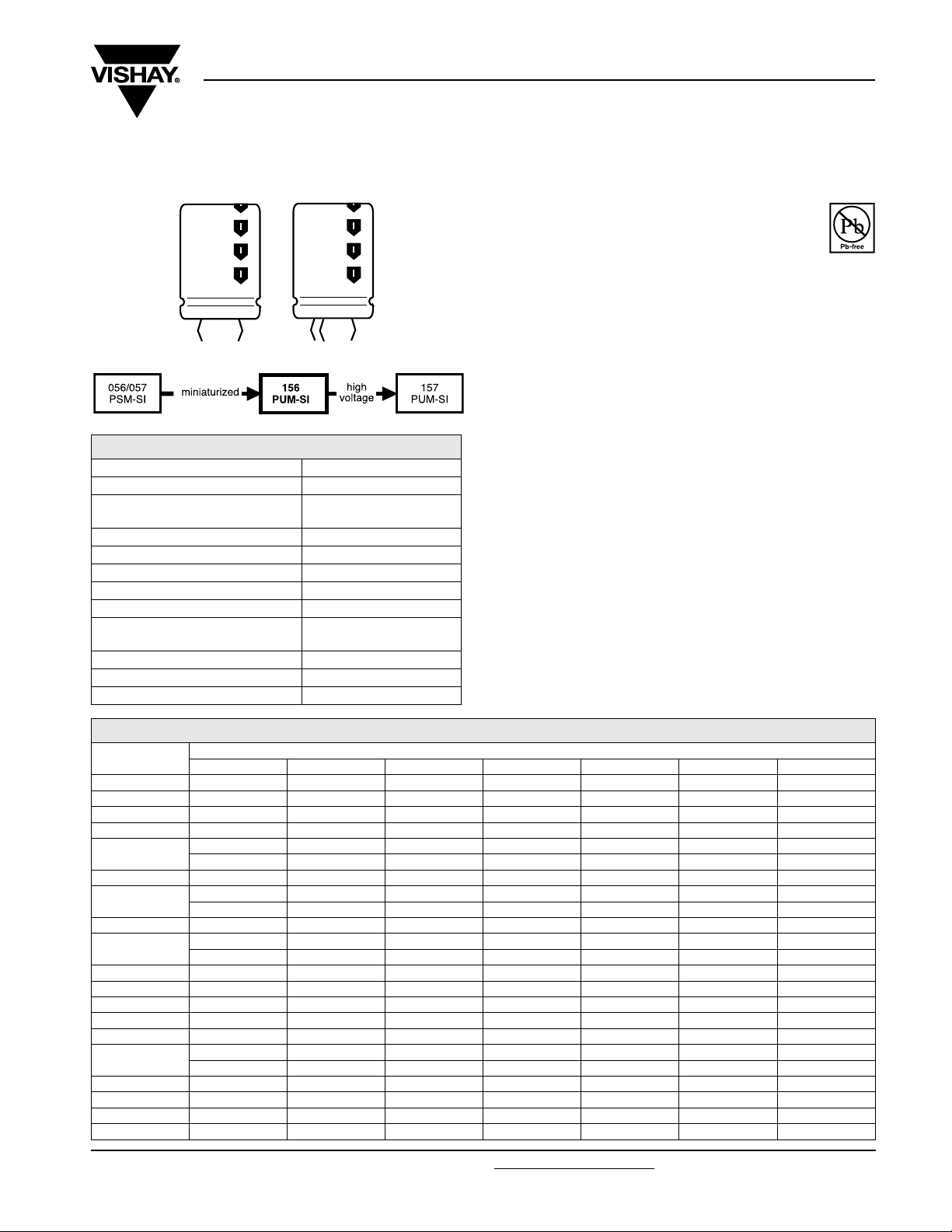
Fig.1 Component outline
QUICK REFERENCE DATA
DESCRIPTION VALUE
Nominal case size (Ø D x L in mm) 22 x 25 to 35 x 60
Rated capacitance range
(E6 series), C
Tolerance on C
Rated voltage range, U
Category temperature range - 40 °C to + 85 °C
Endurance test at 85 °C 2000 hours
Useful life at 85 °C 5000 hours
Useful life at 40 °C and
1.4 x I
Shelf life at 0 V, 85 °C 500 hours
Based on sectional specification IEC 60384-4/EN130300
Climatic category IEC 60068 40/085/56
applied
R
R
R
R
1000 µF to 22 000 µF
± 20 %
10 V to 100 V
90 000 hours
156 PUM-SI
Vishay BCcomponents
FEATURES
• Polarized aluminum electrolytic capacitors,
non-solid electrolyte
• Large types, very small dimensions, cylindrical
aluminum case, insulated with a blue sleeve
• Charge and discharge proof
• Long useful life: 5000 hours at 85 °C
• High ripple current capability
• Keyed polarity version available
APPLICATIONS
• General purpose, industrial and audio/video systems
• Smoothing and filtering
• Standard and switched mode power supplies
• Energy storage in pulse systems
MARKING
The capacitors are marked (where possible) with the
following information:
• Rated capacitance (in µF)
• Tolerance code on rated capacitance, code letter in
accordance with IEC 60062 (M for ± 20 %)
• Rated voltage (in V)
• Date code (YYMM)
• Name of manufacturer
• Code for factory of origin
• ‘-’ sign to identify the negative terminal, visible from the top
and side of the capacitor
• Code number
• Climatic category in accordance with IEC 60068
RoHS
COMPLIANT
SELECTION CHART FOR CR, UR AND RELEVANT NOMINAL CASE SIZES (Ø D x L in mm)
U
C
R
(µF)
1000 ------22x30
1200 ------22x35
1500 ----22x2522x3025x30
1800 ----25x25--
2200
2700 - - 22 x 25 - 25 x 30 - 30 x 35
3300
3900 - - - 25 x 30 25 x 40 - -
4700
5600 - 25 x 25 - 25 x 40 30 x 35 - 6800 - - 25 x 40 30 x 30 30 x 40 30 x 50 35 x 50
8200 - - 30 x 30 30 x 35 30 x 50 - 35 x 60
10 000 25 x 30 22 x 40 30 x 35 30 x 40 35 x 40 35 x 50 12 000 - 25 x 40 30 x 40 30 x 50 35 x 50 - -
15 000
18 000 - 30 x 40 35 x 40 35 x 50 - - 22 000 30 x 35 - 35 x 50 35 x 60 - - 27 000 - 35 x 40 - - - - 39 00035x40------
Document Number: 28337 For technical questions, contact: aluminumcaps2@vishay.com
Revision: 18-Aug-08 35
16 25 40 50 63 80 100
- - - 22 x 25 22 x 30 25 x 30 25 x 40
----25x25-30x30
- - 22 x 30 22 x 30 25 x 35 25 x 40 30 x 40
- - 25 x 25 - - - 35 x 30
- - 25 x 30 25 x 35 22 x 50 30 x 40 30 x 50
- 22 x 25 - - 30 x 30 - 35 x 40
25 x 40 30 x 35 30 x 50 - 35 x 60 - 30x30------
R
(V)
www.vishay.com
Page 3
156 PUM-SI
y
Vishay BCcomponents
Aluminum Capacitors
Power Ultra Miniature Snap-In
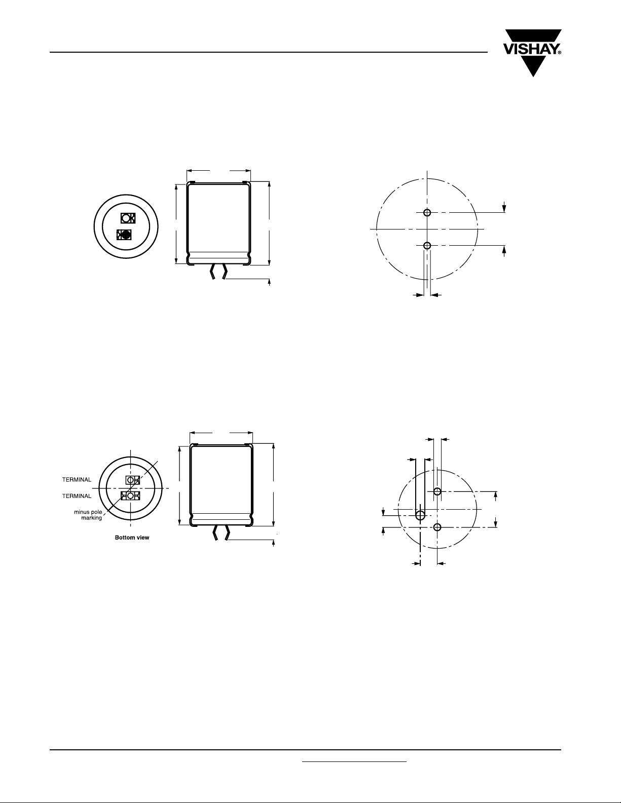
DIMENSIONS in millimeters AND AVAILABLE FORMS
TWO TERMINAL SNAP-IN
Ø D
+ TERMINAL
- TERMINAL
Bottom view
The minus terminal can be marked with a black dot or with an
imprinted ‘−’sign.
Fig.2 Two terminal snap-in
L
L + 2 max.
+ 0
5.8 mm
- 1
10
± 0.1
Ø 2 ± 0.1 (2 x)
Fig.3 Mounting hole diagram
THREE TERMINAL SNAP-IN
Ø D
+
-
L
The negative terminal has TWO pins which are BOTH electricall
connected.
Fig.4 Three terminal snap-in
L + 2 max.
4 ± 0.5
Ø 2 ± 0.1 (2 x)
Ø 2.5 ± 0.1
10 ± 0.1
3.3 ± 0.1
4.75 ± 0.1
The 10 mm spacing of the 2 pin snap-in is used as the base layout
and a third hole is added.
The third hole is closer to the negative primary hole so that
polarization is always maintained, together with added mechanical
stability.
Fig.5 Mounting hole diagram
www.vishay.com For technical questions, contact: aluminumcaps2@vishay.com
Document Number: 28337
36 Revision: 18-Aug-08
Page 4

156 PUM-SI
Aluminum Capacitors
Vishay BCcomponents
Power Ultra Miniature Snap-In
Tab l e 1
DIMENSIONS in millimeters, MASS AND PACKAGING QUANTITIES
NOMINAL
CASE SIZE
Ø D x L
22 x 25 23 27 ≈ 12 100 260 x 250 x 39
22 x 30 23 32 ≈ 16 100 260 x 250 x 44
22 x 35 23 37 ≈ 20 100 260 x 250 x 49
22 x 40 23 42 ≈ 23 100 260 x 250 x 54
22 x 50 23 52 ≈ 29 100 260 x 250 x 64
25 x 25 26 27 ≈ 20 100 290 x 280 x 39
25 x 30 26 32 ≈ 22 100 290 x 280 x 44
25 x 35 26 37 ≈ 24 100 290 x 280 x 49
25 x 40 26 42 ≈ 27 100 290 x 280 x 54
30 x 30 31 32 ≈ 30 100 340 x 330 x 44
30 x 35 31 37 ≈ 35 100 340 x 330 x 49
30 x 40 31 42 ≈ 42 100 340 x 330 x 54
30 x 50 31 52 ≈ 52 100 340 x 330 x 64
35 x 30 36 32 ≈ 40 50 390 x 198 x 44
35 x 40 36 42 ≈ 55 50 390 x 198 x 54
35 x 50 36 52 ≈ 72 50 390 x 198 x 64
35 x 60 36 62 ≈ 84 50 390 x 198 x 74
Ø D
(mm)
max.
L
max.
(mm)
MASS
(g)
PACKAGING QUANTITIES
(units per box)
CARDBOARD BOX DIMENSIONS
L x W x H
ELECTRICAL DATA
SYMBOL DESCRIPTION
C
R
I
R
I
L1
ESR max. equivalent series resistance at 100 Hz
Z max. impedance at 10 kHz
Note
• Unless otherwise specified, all electrical values in Table 2 apply
at T
amb
Tab l e 2
rated capacitance at 100 Hz
rated rms ripple current at 100 Hz and 85 ×C
max. leakage current after 1 minute at u
= 20 °C, P = 86 to 106 kPa, RH = 45 to 75 %
r
ORDERING EXAMPLE
Electrolytic capacitor 156 series
1000 µF/25 V; ± 20 %
Nominal case size: Ø 25 x 40 mm
2-terminal snap-in:
Ordering code: MAL2156 26123E3
Former 12NC: 2222156 26123
3-terminal snap-in:
Ordering code: MAL2156 66123E3
Former 12NC: 2222156 66123
ELECTRICAL DATA AND ORDERING INFORMATION
C
U
R
(V)
16
25
Document Number: 28337 For technical questions, contact: aluminumcaps2@vishay.com
Revision: 18-Aug-08 37
R
100 Hz
(µF)
10 000 25 x 30 3.93 324 49 33 25103E3 65103E3
15 000 25 x 40 4.98 484 36 26 35153E3 75153E3
18 000 30 x 30 4.12 580 53 33 35183E3 75183E3
22 000 30 x 35 4.71 708 44 29 25223E3 65223E3
39 000 35 x 40 5.17 1252 45 26 25393E3 65393E3
4700 22 x 25 2.37 239 100 90 16472E3 56472E3
5600 25 x 25 3.03 284 74 46 26562E3 66562E3
10 000 22 x 40 4.40 504 41 27 16103E3 56103E3
12 000 25 x 40 4.73 604 40 27 26123E3 66123E3
15 000 30 x 35 4.55 754 47 31 26153E3 66153E3
18 000 30 x 40 5.06 904 41 27 16183E3 56183E3
27 000 35 x 40 5.04 1354 47 27 26273E3 66273E3
NOMINAL
CASE SIZE
Ø D x L
(mm)
I
R
100 Hz
85 °C
(A)
I
L5
5 min
(µA)
MAX. ESR
100 Hz
(mΩ)
MAX. Z
10 kHz
(mΩ)
ORDERING
CODE
MAL2156.......
2-TERM. 3-TERM.
www.vishay.com
Page 5

156 PUM-SI
Vishay BCcomponents
Aluminum Capacitors
Power Ultra Miniature Snap-In
ELECTRICAL DATA AND ORDERING INFORMATION
C
U
R
(V)
40
50
63
80
100
www.vishay.com For technical questions, contact: aluminumcaps2@vishay.com
38 Revision: 18-Aug-08
R
100 Hz
(µF)
2700 22 x 25 2.47 220 97 57 17272E3 57272E3
3300 22 x 30 2.98 268 74 43 27332E3 67332E3
3300 25 x 25 2.69 268 93 58 17332E3 57332E3
4700 25 x 30 3.32 380 68 44 27472E3 67472E3
6800 25 x 40 4.26 548 49 33 37682E3 77682E3
8200 30 x 30 3.49 660 74 44 37822E3 77822E3
10 000 30 x 35 4.02 804 60 38 17103E3 57103E3
12 000 30 x 40 4.49 964 52 33 17123E3 57123E3
15 000 30 x 50 5.39 1204 41 28 37153E3 77153E3
18 000 35 x 40 4.39 1444 62 33 17183E3 57183E3
22 000 35 x 50 5.34 1764 47 28 27223E3 67223E3
2200 22 x 25 2.34 224 107 62 11222E3 51222E3
3300 22 x 30 2.92 334 76 46 11332E3 51332E3
3900 25 x 30 3.17 394 74 47 21392E3 61392E3
4700 25 x 35 3.64 474 62 40 21472E3 61472E3
5600 25 x 40 4.09 564 53 35 21562E3 61562E3
6800 30 x 30 3.35 684 79 48 21682E3 61682E3
8200 30 x 35 3.88 824 65 40 21822E3 61822E3
10 000 30 x 40 4.32 1004 56 35 11103E3 51103E3
12 000 30 x 50 5.23 1204 43 29 11123E3 51123E3
18 000 35 x 50 5.18 1804 50 29 11183E3 51183E3
22 000 35 x 60 5.97 2204 51 46 11223E3 51223E3
1500 22 x 25 2.13 193 128 68 18152E3 58152E3
1800 25 x 25 2.37 231 120 69 18182E3 58182E3
2200 22 x 30 2.66 281 92 50 18222E3 58222E3
2200 25 x 25 2.42 281 115 70 28222E3 68222E3
2700 25 x 30 2.95 344 86 51 28272E3 68272E3
3300 25 x 35 3.39 420 71 43 28332E3 68332E3
3900 25 x 40 3.81 495 61 37 28392E3 68392E3
4700 22 x 50 4.26 596 50 30 18472E3 58472E3
4700 30 x 30 3.25 596 85 53 38472E3 78472E3
5600 30 x 35 3.75 710 69 45 28562E3 68562E3
6800 30 x 40 4.19 861 59 39 18682E3 58682E3
6800 35 x 30 3.28 861 97 53 28682E3 68682E3
8200 30 x 50 5.05 1037 46 32 38822E3 78822E3
10 000 35 x 40 4.23 1264 67 39 18103E3 58103E3
12 000 35 x 50 5.15 1516 51 32 18123E3 58123E3
15 000 35 x 60 5.89 1894 52 47 18153E3 58153E3
1500 22 x 30 1.83 244 318 308 12152E3 52152E3
2200 25 x 30 2.23 356 230 224 22222E3 62222E3
3300 25 x 40 2.92 532 155 152 22332E3 62332E3
4700 30 x 40 3.44 756 121 119 12472E3 52472E3
6800 30 x 50 4.18 1092 88 87 12682E3 52682E3
10 000 35 x 50 4.51 1604 74 73 12103E3 52103E3
1000 22 x 30 1.72 204 338 312 19102E3 59102E3
1200 22 x 35 1.98 244 282 261 29122E3 59122E3
1500 25 x 30 2.12 304 239 223 29152E3 69152E3
2200 25 x 40 2.77 444 164 154 29222E3 69222E3
2200 30 x 30 2.55 444 181 171 39222E3 79222E3
2700 30 x 35 2.94 544 148 140 29272E3 69272E3
3300 30 x 40 3.32 664 123 116 19332E3 59332E3
3300 35 x 30 2.84 664 147 140 29332E3 69332E3
4700 30 x 50 4.04 944 90 86 19472E3 59472E3
4700 35 x 40 3.67 944 102 98 29472E3 69472E3
6800 35 x 50 4.39 1364 76 73 19682E3 59682E3
8200 35 x 60 5.21 1644 63 61 19822E3 59822E3
NOMINAL
CASE SIZE
Ø D x L
(mm)
I
R
100 Hz
85 °C
(A)
I
L5
5 min
(µA)
MAX. ESR
100 Hz
(mΩ)
MAX. Z
10 kHz
(mΩ)
ORDERING
CODE
MAL2156.......
2-TERM. 3-TERM.
Document Number: 28337
Page 6

156 PUM-SI
Aluminum Capacitors
Power Ultra Miniature Snap-In
ADDITIONAL ELECTRICAL DATA
PARAMETER CONDITIONS VALUE
Voltage
Surge voltage
Reverse voltage
Current
Leakage current
Inductance
Equivalent series inductance (ESL) All case sizes
RIPPLE CURRENT AND USEFUL LIFE
After 1 minute at U
After 5 minutes at U
2.4
2.3
I
A
I
R
2.2
Vishay BCcomponents
U
= 1.15 x U
s
≤ 1V
U
rev
R
R
IL1≤ 0.006 CR x UR+4µA
IL5≤ 0.002 CR x UR+4µA
typ. 19 nH
max. 25 nH
R
MGA453
IA= Actual ripple current at 100 Hz
I
= Rated ripple current at 100 Hz and 85 °C
R
(1)
Useful life at 85 °C and IR applied: 5000 hours
2.1
2.0
1.9
1.8
1.7
1.6
1.5
1.4
1.3
1.2
1.1
1.0
0.8
0.5
0.0
40 50 60 70 80 90
30
45
60
10
15
20
4
5
8
2
2.5
3
1.5
1.2
1
life multiplier
(1)
(°C)
T
amb
Fig.6 Multiplier of useful life as a function of ambient temperature and ripple current load
Document Number: 28337 For technical questions, contact: aluminumcaps2@vishay.com
Revision: 18-Aug-08 39
www.vishay.com
Page 7

156 PUM-SI
Vishay BCcomponents
Aluminum Capacitors
Power Ultra Miniature Snap-In
Tab l e 3
MULTIPLIER OF RIPPLE CURRENT (IR) AS A FUNCTION OF FREQUENCY
I
MULTIPLIER
FREQUENCY
(Hz)
50 0.93 0.91
100 1.00 1.00
200 1.04 1.05
400 1.07 1.09
1000 1.11 1.13
2000 1.13 1.15
4000 1.15 1.18
≥ 10 000 1.18 1.22
Tab l e 4
=10to25V UR= 40 to 100 V
U
R
TEST PROCEDURES AND REQUIREMENTS
TEST
NAME OF TEST REFERENCE
Endurance IEC 60384-4/
Useful life CECC 30301
Shelf life
(storage at
high temperature)
EN130300
subclause 4.13
subclause 1.8.1
IEC 60384-4/
EN130300
subclause 4.17
T
=85°C; UR applied:
amb
2000 hours
= 85 °C; UR and IR applied:
T
amb
5000 hours
T
= 85 °C; no voltage applied;
amb
500 hours
After test: U
24 hours to 48 hours before measurement
PROCEDURE
(quick reference)
to be applied for 30 minutes,
R
R
ΔC/C: ± 15 %
ESR ≤ 1.3 x spec. limit
Z ≤ 2 x spec. limit
≤ spec. limit
I
L5
ΔC/C: ± 15 %
ESR ≤ 3 x spec. limit
Z ≤ 3 x spec. limit
≤ spec. limit
I
L5
no short or open circuit,
no visible damage
total failure percentage: ≤ 1 %
ΔC/C: ± 10 %
ESR ≤ 1.2 x spec. limit
I
≤ 2 x spec. limit
L5
REQUIREMENTS
www.vishay.com For technical questions, contact: aluminumcaps2@vishay.com
40 Revision: 18-Aug-08
Document Number: 28337
Page 8

Legal Disclaimer Notice
Vishay
Disclaimer
All product specifications and data are subject to change without notice.
Vishay Intertechnology, Inc., its affiliates, agents, and employees, and all persons acting on its or their behalf
(collectively, “Vishay”), disclaim any and all liability for any errors, inaccuracies or incompleteness contained herein
or in any other disclosure relating to any product.
Vishay disclaims any and all liability arising out of the use or application of any product described herein or of any
information provided herein to the maximum extent permitted by law. The product specifications do not expand or
otherwise modify Vishay’s terms and conditions of purchase, including but not limited to the warranty expressed
therein, which apply to these products.
No license, express or implied, by estoppel or otherwise, to any intellectual property rights is granted by this
document or by any conduct of Vishay.
The products shown herein are not designed for use in medical, life-saving, or life-sustaining applications unless
otherwise expressly indicated. Customers using or selling Vishay products not expressly indicated for use in such
applications do so entirely at their own risk and agree to fully indemnify Vishay for any damages arising or resulting
from such use or sale. Please contact authorized Vishay personnel to obtain written terms and conditions regarding
products designed for such applications.
Product names and markings noted herein may be trademarks of their respective owners.
Document Number: 91000 www.vishay.com
Revision: 18-Jul-08 1
 Loading...