

Page 1

6121 Baker Road,
Suite 108
Minnetonka, MN 55345
www.chtechnology.com
Phone (952) 933-6190
Fax (952) 933-6223
1-800-274-4284
Thank you for downloading this document from C&H Technology, Inc.
Please contact the C&H Technology team for the following questions -
Technical
Application
Assembly
Availability
Pricing
Phone – 1-800-274-4284
E-Mail – sales@chtechnology.com
www.chtechnology.com - SPECIALISTS IN POWER ELECTRONIC COMPONENTS AND ASSEMBLIES - www.chtechnology.com
Page 2
Aluminum Capacitors Solid Al,
Radial Pearl Miniature
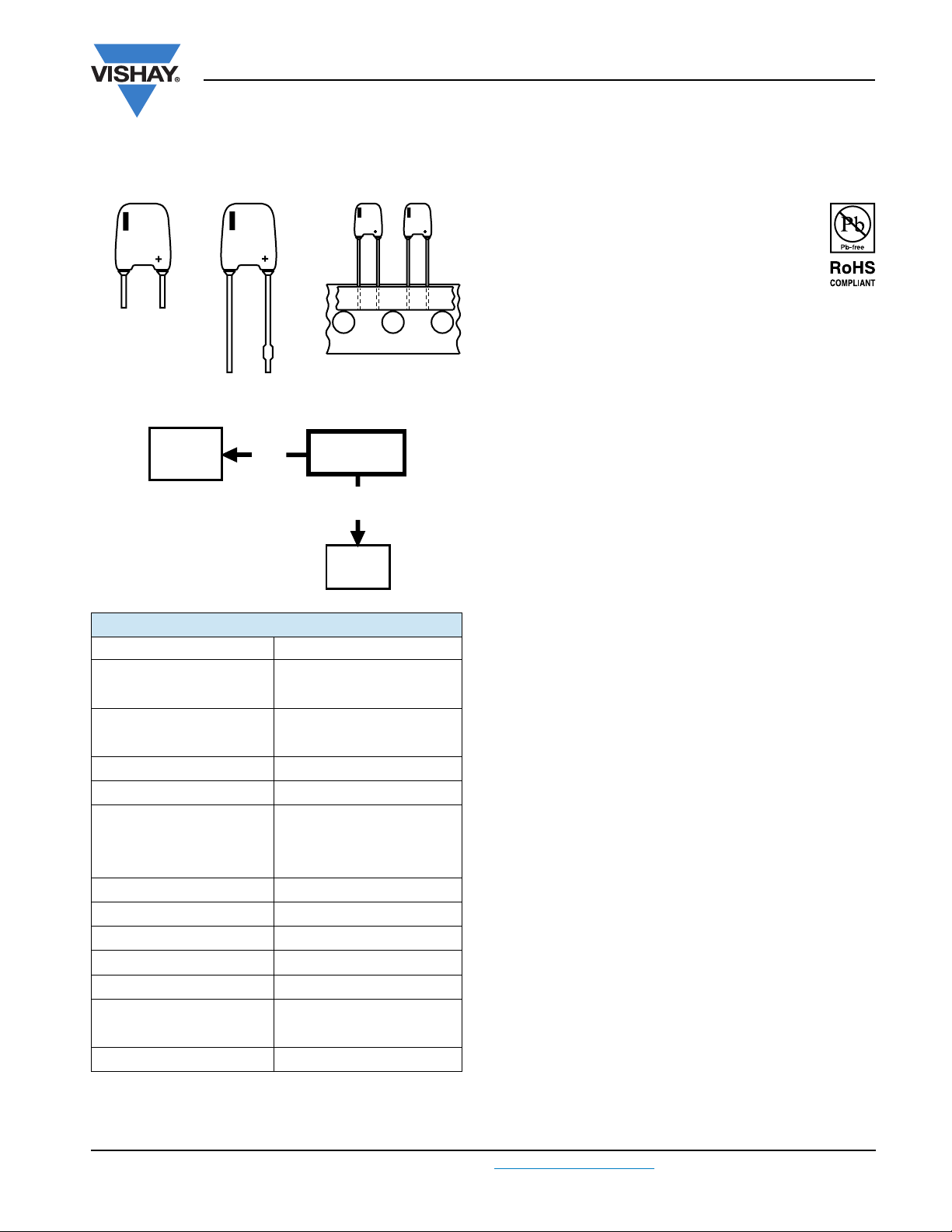
Fig.1 Component outlines
123
SAL-A
axial
version
QUICK REFERENCE DATA
DESCRIPTION VALUE
Maximum case sizes
(H x W x T in mm)
128
SAL-RPM
175 °C
solid SMD
175 TMP
10x7x3.5
to10x8x6
128 SAL-RPM
Vishay BCcomponents
FEATURES
• Polarized aluminum electrolytic capacitors,
solid electrolyte MnO
• Radial leads, max. height 10 mm, resin
dipped, orange colored
• Extremely long useful life, 20 000 hours/125 °C
• Extended high temperature range up to 175 °C
• Excellent low temperature, impedance and ESR behaviour
• Charge and discharge proof, application with 0 Ω
resistance allowed
• Reverse DC voltage up to 0.3 x U
• AC voltage up to 0.8 x U
• Compliant to RoHS directive 2002/95/EC
APPLICATIONS
• Audio-video, automotive, industrial high temperature and
telecommunication
• Smoothing, filtering and buffering
• For small power supplies, DC/DC converters
MARKING
The capacitors are marked (where possible) with the
following information:
2
allowed
R
allowed
R
Rated capacitance range
(E6 series), C
Tolerance on C
Rated voltage range, U
Category temperature range:
= 6.3 V to 40 V - 55 °C to + 85 °C
U
R
= 6.3 V to 25 V - 55 °C to + 125 °C
U
C
Endurance test at 125 °C 10 000 hours
Useful life at 125 °C 20 000 hours
Useful life at 175 °C 2000 hours
Useful life at 40 °C, I
Shelf life at 0 V, 125 °C 500 hours
Based on sectional
specification
Climatic category IEC 60068 55/125/56
R
R
R
applied > 300 000 hours
R
0.22 µF to 68 µF
± 20 %
6.3 V to 40 V
IEC 60384-4/EN 130300
• Rated capacitance (in µF)
• Tolerance on rated capacitance, code letter in accordance
with IEC 60062 (M for ± 20 %)
• Rated voltage (in V) and category voltage if applicable
• Date code in accordance with IEC60062
• Name of manufacturer
• ‘I’ sign to indicate the negative terminal
• ‘+’ sign to identify the positive terminal
• Series number
MOUNTING
When bending, cutting or straightening the leads, ensure that
the capacitor body is relieved of stress.
Bending after soldering must be avoided.
Completely sealing the component’s body or use in an
oxygen-free environment has a negative impact on useful
life.
Document Number: 28354 For technical questions, contact: aluminumcaps2@vishay.com
Revision: 31-Aug-09 153
www.vishay.com
Page 3
128 SAL-RPM
.
Vishay BCcomponents
Aluminum Capacitors Solid Al,
Radial Pearl Miniature
SELECTION CHART FOR CR, UR, UC AND RELEVANT MAXIMUM CASE SIZES (H x W x T in mm)
U
(V) at T
R
C
(µF)
R
6.310162540
U
(V) at T
C
6.310162525
0.22 - - - - 10 x 7 x 3.5
0.33 - - - - 10 x 7 x 4
0.47 - - - - 10 x 7 x 5
0.68 - - - 10 x 7 x 3.5 10 x 7 x 5
1 - - - 10 x 7 x 3.5 10 x 7 x 5
1.5 - - - 10 x 7 x 3.5 10 x 8 x 6
2.2 - - 10 x 7 x 3.5 10 x 7 x 4 10 x 8 x 6
3.3 - - 10 x 7 x 3.5 10 x 7 x 5 -
4.7 - 10 x 7 x 3.5 10 x 7 x 4 10 x 8 x 5 -
6.8 - 10 x 7 x 3.5 10 x 7 x 4 10 x 8 x 5 10 10 x 7 x 3.5 10 x 7 x 4 10 x 7 x 5 10 x 8 x 6 15 - 10 x 7 x 4 10 x 8 x 5 - 22 10 x 7 x 4 10 x 7 x 5 10 x 8 x 6 - 33 10 x 7 x 5 10 x 8 x 5 - - 47 10 x 8 x 5 10 x 8 x 6 - - 68 10 x 8 x 6 - - - -
amb
= 125 °C
amb
= 85 °C
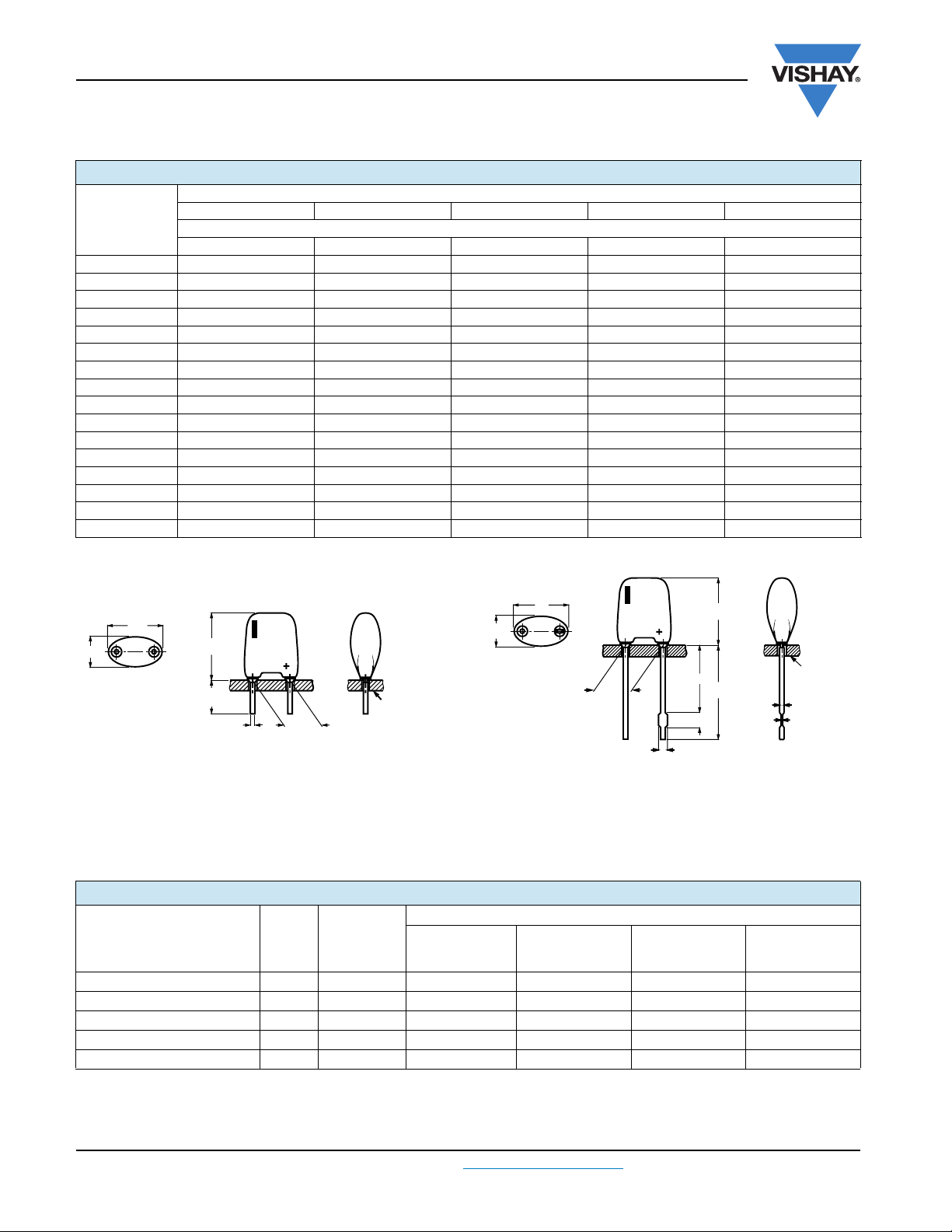
DIMENSIONS in millimeters AND AVAILABLE FORMS
W
W
T
Bottom view
The diameter of the mounting holes in the printed-circuit board is 0.8 ± 0.1 mm
Flanges are provided with degassing grooves.
9.5 ± 0.5
+ 0.3
4.5
- 0.7
Ø 0.6
- 0.05
+ 0.06
5.2 ± 0.2
Printed-circuit
board
Fig.2 Form CB: Short leads, in boxes
T
Bottom view
5.2 ± 0.2
The diameter of the mounting holes in the printed-circuit board is 0.8 ± 0.1 mm,
except for the hole of the anode lead of Form CA capacitors: 1.3 - 0.2 mm.
Flanges are provided with degassing grooves.
Fig.3 Form CA: Long leads with keyed polarity, in boxes
Tab l e 1
DIMENSIONS in millimeters, MASS AND PACKAGING QUANTITIES
MAXIMUM
CASE SIZE
H x W x T
(mm)
CASE
CODE
MASS
(g)
FORM
(1)
CA
10x7x3.5 20 ≈ 0.25 1000 1000 2000 1000
10x7x4 30 ≈ 0.30 1000 1000 2000 1000
10x7x5 40 ≈ 0.35 1000 1000 1000 1000
10x8x5 50 ≈ 0.50 1000 1000 1000 1000
10x8x6 60 ≈ 0.60 1000 1000 1000 1000
PACKAGING QUANTITIES
FORM
(1)
CB
1.0 ± 0.1
FORM
9 ± 1
2 ± 0.5
TR+
9.5 ± 0.5
12.5 ± 0.5
0.25
± 0.05
Printed-circuit
board
+ 0.06
Ø 0.6
- 0.05
FORM
TFA
Notes
(1)
In plastic bags of 200 units each.
Detailed tape dimensions see section ‘PACKAGING’.
www.vishay.com For technical questions, contact: aluminumcaps2@vishay.com
154 Revision: 31-Aug-09
Document Number: 28354
Page 4
128 SAL-RPM
Aluminum Capacitors Solid Al,
Vishay BCcomponents
Radial Pearl Miniature
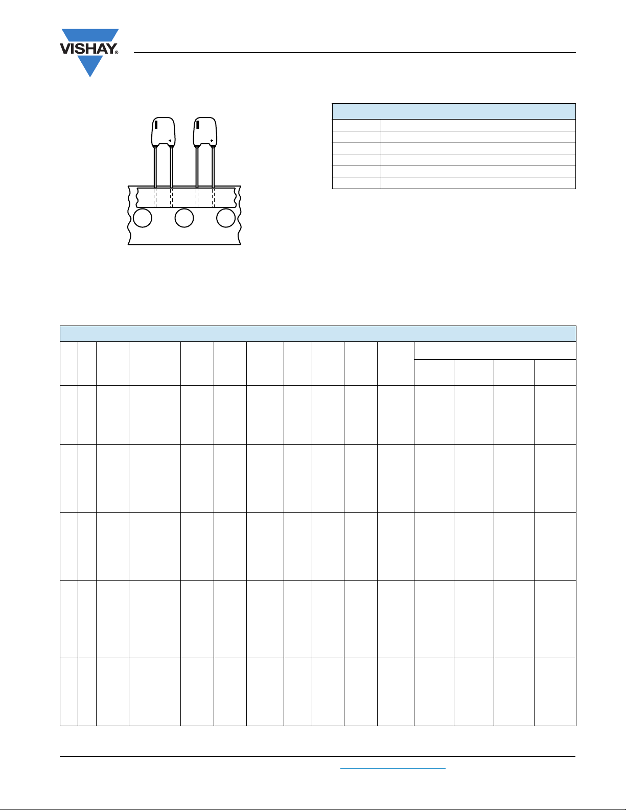
TAPED PRODUCTS
Form TR +: Taped on reel, positive leading
Form TFA : Taped in ammopack
Fig.4 Taped versions
Tab l e 2
ELECTRICAL DATA AND ORDERING INFORMATION
MAXIMUM
C
R
U
U
C
R
(V)
100 Hz
(V)
6.3 6.3
10 10
16 16
25 25
25 40
Note
tan δ at 100 Hz for all types < 0.10
Document Number: 28354 For technical questions, contact: aluminumcaps2@vishay.com
Revision: 31-Aug-09 155
CASE SIZE
(µF)
H x W x T
(mm)
10 10 x 7 x 3.5 22.4 320 595 2 20 8 2.0
22 10 x 7 x 4 32.9 470 870 4 9 3.5 1.0 53229E3 73229E3 23229E3 33229E3
33 10 x 7 x 5 65.4 595 1100 5 6.1 2 0.70 53339E3 73339E3 23339E3 33339E3
47 10 x 8 x 5 118.4 740 1360 7 4.3 2 0.50 53479E3 73479E3 23479E3 33479E3
68 10 x 8 x 6 153.0 800 1650 11 3.0 1.5 0.40 53689E3 73689E3 23689E3 33689E3
4.7 10 x 7 x 3.5 16.1 230 425 2 43 16 3.00 54478E3 74478E3 24478E3 34478E3
6.8 10 x 7 x 3.5 18.9 270 500 2 30 12 2.20 54688E3 74688E3 24688E3 34688E3
10 10 x 7 x 4 21.7 310 573 3 20 9 1.70 54109E3 74109E3 24109E3 34109E3
15 10 x 7 x 4 27.3 390 720 4 14 7 1.20 54159E3 74159E3 24159E3 34159E3
22 10 x 7 x 5 51.7 470 870 6 9 3.5 0.90 54229E3 74229E3 24229E3 34229E3
33 10 x 8 x 5 81.6 510 940 8 6.1 2 0.60 54339E3 74339E3 24339E3 34339E3
47 10 x 8 x 6 105.4 620 1140 12 4.3 1.5 0.40 54479E3 74479E3 24479E3 34479E3
2.2 10 x 7 x 3.5 14.0 200 370 2 91 25 4.50 55228E3 75228E3 25228E3 35228E3
3.3 10 x 7 x 3.5 16.1 230 425 2 61 26 3.30 55338E3 75338E3 25338E3 35338E3
4.7 10 x 7 x 4 18.9 270 500 2 43 14 2.30 55478E3 75478E3 25478E3 35478E3
6.8 10 x 7 x 4 22.4 320 590 3 30 11 1.65 55688E3 75688E3 25688E3 35688E3
10 10 x 7 x 5 42.9 390 720 4 20 6 1.10 55109E3 75109E3 25109E3 35109E3
15 10 x 8 x 5 71.2 445 820 6 14 5 0.85 55159E3 75159E3 25159E3 35159E3
22 10 x 8 x 6 86.7 510 940 9 9 3.5 0.65 55229E3 75229E3 25229E3 35229E3
0.68 10 x 7 x 3.5 7.7 110 200 2 295 85 17.00 56687E3 76687E3 26687E3 36687E3
1 10 x 7 x 3.5 9.1 130 240 2 200 71 12.50 56108E3 76108E3 26108E3 36108E3
1.5 10 x 7 x 3.5 10.8 155 285 2 135 48 10.00 56158E3 76158E3 26158E3 36158E3
2.2 10 x 7 x 4 13.6 195 360 2 91 34 7.00 56228E3 76228E3 26228E3 36228E3
3.3 10 x 7 x 5 16.1 230 425 2 61 19 5.20 56338E3 76338E3 26338E3 36338E3
4.7 10 x 8 x 5 25.3 270 500 3 43 14 3.50 56478E3 76478E3 26478E3 36478E3
6.8 10 x 8 x 6 52.7 310 570 4 30 11 2.70 56688E3 76688E3 26688E3 36688E3
10 10 x 8 x 6 64.8 360 660 6 20 9 2.00 56109E3 76109E3 26109E3 36109E3
0.22 10 x 7 x 3.5 4.2 60 115 2 910 275 27.00 57227E3 77227E3 27227E3 37227E3
0.33 10 x 7 x 4 5.3 75 140 2 610 172 20.00 57337E3 77337E3 27337E3 37337E3
0.47 10 x 7 x 5 10.4 95 175 2 430 114 15.00 57477E3 77477E3 27477E3 37477E3
0.68 10 x 7 x 5 12.1 110 205 2 295 89 10.00 57687E3 77687E3 27687E3 37687E3
1 10 x 8 x 5 20.0 125 230 2 200 45 7.00 57108E3 77108E3 27108E3 37108E3
1.5 10 x 8 x 6 25.5 150 280 2 135 35 5.50 57158E3 77158E3 27158E3 37158E3
2.2 10 x 8 x 6 33.1 195 360 2 91 28 4.20 57228E3 77228E3 27228E3 37228E3
I
R
100 Hz
125 °C
(mA)
I
R
10 kHz
85 °C
(mA)
I
R
100 kHz
40 °C
(mA)
I
L5
5min
(µA)
ELECTRICAL DATA
C
R
I
R
I
L5
tan δ max. dissipation factor at 100 Hz
ESR max./typ. equivalent series resistance at 100 Hz
Z max. impedance at 100 kHz
Note
Unless otherwise specified, all electrical values in Table 2
T
= 20 °Cto 25°C, P = 86 kPa to 106 kPa, RH = 45 % to 75 %
amb
rated capacitance at 100 Hz, tolerance ± 20 %
max. RMS ripple current no necessary DC applied
max. leakage current after 5 minutes at U
ORDERING EXAMPLE
Maximum case size: 10 mm x 7 mm x 5 mm; Form CB
Electrolytic capacitors 128 series 10 µF/16 V; ± 20 %
Ordering code: MAL2128 55109E3
Former 12NC: 2281128 55109
MAX.
ESR
100 Hz
(Ω)
TYP.
ESR
100 Hz
(Ω)
Z
100 kHz
(Ω)
FORMCBFORM
53109E3
E3
ORDERING CODE
MAL2128.......
CA
73109E3 23109E3 33109E3
FORM
TR +
REEL
R
apply at
FORM
TFA
AMMO
www.vishay.com
.
Page 5

128 SAL-RPM
Vishay BCcomponents
Aluminum Capacitors Solid Al,
Radial Pearl Miniature
ADDITIONAL ELECTRICAL DATA
PARAMETER CONDITIONS VALUE
Voltag e
Surge voltage U
Reverse voltage U
Maximum peak AC voltage Reverse voltage applied ≤ 2V
Maximum peak AC voltage,
without reverse voltage applied
Inductance
Equivalent series inductance (ESL) Case sizes 10 mm x 7 mm x 3.5 mm to
Dissipation
Maximum power dissipation Case sizes 10 mm x 7 mm x 3.5 mm to
Current
Maximum leakage current After 5 minutes at U
Typical leakage current 15 s at U
VOLTAGE
≤ 85 °C:
T
amb
at f ≤ 0.1 Hz 0.30 x U
at 0.1 Hz < f ≤ 1Hz 0.45xU
at 1 Hz < f ≤ 10 Hz 0.60 x U
at 10 Hz < f ≤ 50 Hz 0.65 x U
at f > 50 Hz 0.80 x U
85 °C < T
amb
≤ 125 °C:
at f ≤ 0.1 Hz 0.15 x U
at 0.1 Hz < f ≤ 1Hz 0.22xU
at 1 Hz < f ≤ 10 Hz 0.30 x U
at 10 Hz < f ≤ 50 Hz 0.32 x U
at f > 50 Hz 0.40 x U
10 mm x 7 mm x 5 mm
Case sizes 10 mm x 8 mm x 5 mm and
10 mm x 8 mm x 6 mm
All case sizes max. 20 nH
10 mm x 7 mm x 5 mm
Case sizes 10 mm x 8 mm x 5 mm and
10 mm x 8 mm x 6 mm
and T
R
and T
R
U
= 6.3 V to 16 V ≈ 0.2 x value stated in Table 2
R
= 25 V to 40 V ≈ 0.1 x value stated in Table 2
U
R
amb
=25°C:
=25°CI
amb
≤ 1.15 x U
s
< 0.3 x U
rev
R
R
R
R
R
R
R
R
R
R
R
R
typ. 9 nH to 14 nH
typ. 11 nH to 16 nH
P
=88mW
125
P
= 104 mW
125
≤ 0.025 CR x UR or 2 µA
L5
whichever is greater; see Table 2
40
(1)
35
25
16
10
6.3
4
0
UC = 125 °C
(2)
UC = 175 °C
- 50 0 50 100 150 175
85 125
Fig.5 Maximum permissible voltage up to T
(1)
= 175 °C
amb
T
amb
(2)
(°C)
RIPPLE CURRENT (IR)
T
PARAMETER
multiplier 1.1 1.0 0.88 0.75 0.59 0.37
I
R
25 °C40°C65°C85°C 105 °C 125 °C
Notes
(1)
Applying the maximum RMS ripple current given in Table 2 will
cause a device temperature of 138 °C
(2)
The 100 kHz values in Table 2 for other temperatures are to be
calculated with the above I
multipliers:
R
amb
www.vishay.com For technical questions, contact: aluminumcaps2@vishay.com
Document Number: 28354
156 Revision: 31-Aug-09
Page 6

128 SAL-RPM
5
Aluminum Capacitors Solid Al,
Radial Pearl Miniature
CAPACITANCE (C)
1.2
C
C
0
1.1
1.0
0.9
0.8
0.7
0.6
- 80 - 40 0 40 80 120 160
Fig.6 Typical multiplier of capacitance and standard deviation
as functions of ambient temperature
σ
Vishay BCcomponents
TYPICAL CAPACITANCE CHANGE AFTER
ENDURANCE TEST AT T
4
ΔC
(%)
2
σ
viation
standard de
0.0
0
T
(°C)
amb
0
- 2
- 4
- 6
- 8
- 10
0.01 0.1 0.5 1 2 5 10 20 30 40 50 60 70 80 90 95 98 99 99.5 99.9 99.99
Fig.7 Change of capacitance as a function of cumulative
frequency after endurance test
= 125 °C
AMB
cumulative frequency (%)
2000 h
5000 h
10 000 h
LEAKAGE CURRENT
2
10
I
I
0
10
1
-1
10
- 40 0 40 80 120 160
= leakage current during continuous operation
I
0
and T
at U
R
= 25 °C
amb
Fig.8 Typical multiplier of leakage current as a function
of ambient temperature
TYPICAL LEAKAGE CURRENT CHANGE
AFTER ENDURANCE TEST AT T
100
80
60
50
40
30
20
10
8
6
5
4
3
2
leakage current (% of initial requirements)
1
0.01 0.1 0.5 1 2 5 10 20 30 40 50 60 70 80 90 95 98 99 99.5 99.9 99.99
T
(°C)
amb
Fig.9 Change of capacitance as a function of cumulative
frequency after endurance test
cumulative frequency (%)
AMB
2000 h
= 125 °C
init.
5000 h
10 000 h
Document Number: 28354 For technical questions, contact: aluminumcaps2@vishay.com
www.vishay.com
Revision: 31-Aug-09 157
Page 7

128 SAL-RPM
Vishay BCcomponents
Aluminum Capacitors Solid Al,
Radial Pearl Miniature
DISSIPATION FACTOR (tan δ)
2.0
tan δ
tan δ
0
1.5
1.0
0.5
0
- 80 - 40 0 40 80 120 160
Tan δ
= dissipation factor at Tamb = 25 °C and 100 Hz
0
Fig.10 Typical multiplier of dissipation factor and standard deviation
as functions of ambient temperature
σ
T
(°C)
amb
0.05
0
TYPICAL tan δ CHANGE AFTER
ENDURANCE TEST AT T
120
100
80
60
standard deviation σ
40
tan δ (% of initial requirements)
20
0
0.01 0.1 0.5 1 2 5 10 20 30 40 50 60 70 80 90 95 98 99 99.5 99.9 99.99
Fig.11 tan δ change of capacitance as a function of cumulative
frequency after endurance test
= 125 °C
amb
2000 h
cumulative frequency (%)
init.
5000 h
10 000 h
EQUIVALENT SERIES RESISTANCE (ESR)
4
10
ESR
ESR
0
3
10
1
2
10
10
1
-1
10
- 100 - 50 0 50 100 150
2
3
4
5
Fig.12 Typical multiplier of ESR at 100 Hz as a function of
ambient temperature
Curve 1: 0.22 µF, 40 V
Curve 2: 1.5 µF, 40 V
Curve 3: 3.3 µF, 25 V
Curve 4: 10 µF, 6.3 V
Curve 5: 22 µF, 10 V
T
(°C)
amb
3
10
ESR
(Ω)
2
10
10
1
-1
10
Case H x W x T = 10 x 7 x 3.5 mm
-2
10
2
10
3
10
1
2
3
4
4
10
Curve 1: 0.22 µF, 40 V
Curve 2: 1.5 µF, 40 V
Curve 3: 2.2 µF, 16 V
Curve 4: 10 µF, 6.3 V
5
10
Fig.13 Typical ESR at 25 °C as a function of frequency
6
10
f (Hz)
7
10
www.vishay.com For technical questions, contact: aluminumcaps2@vishay.com
Document Number: 28354
158 Revision: 31-Aug-09
Page 8

128 SAL-RPM
Aluminum Capacitors Solid Al,
Radial Pearl Miniature
EQUIVALENT SERIES RESISTANCE (ESR)
3
10
ESR
(Ω)
2
10
1
10
1
2
1
-1
10
Case H x W x T = 10 x 7 x 4 mm
-2
10
2
10
3
3
10
4
10
Fig.14 Typical ESR at 25 °C as a function of frequency
3
10
ESR
(Ω)
2
10
10
1
10
1
-1
1
2
3
Curve 1: 2.2 µF, 25 V
Curve 1: 4.7 µF, 16 V
Curve 1: 22 µF, 6.3 V
5
10
10
Curve 1: 1 µF, 40 V
Curve 2: 4.7 µF, 25 V
Curve 3: 47 µF, 6.3 V
6
f (Hz)
10
Vishay BCcomponents
3
10
ESR
(Ω)
2
10
1
10
1
-1
10
Case size H x W x T = 10 x 7 x 5 mm
-2
7
10
2
10
2
3
4
3
10
4
10
Fig.15 Typical ESR at 25 °C as a function of frequency
3
10
ESR
(Ω)
2
10
1
10
1
1
10
-1
2
3
Curve 1: 0.47 µF, 40 V
Curve 2: 3.3 µF, 40 V
Curve 3: 10 µF, 16 V
Curve 4: 33 µF, 6.3 V
5
10
Curve 1: 10 µF, 25 V
Curve 2: 22 µF, 16 V
Curve 3: 68 µF, 6.3 V
6
10
f (Hz)
7
10
Case size H x W x T = 10 x 8 x 5 mm
-2
10
2
10
3
10
Fig.16 Typical ESR as a function of frequency
4
10
5
10
6
10
f (Hz)
7
10
Case size H x W x T = 10 x 8 x 5 mm
-2
10
2
10
3
10
4
10
5
10
Fig.17 Typical ESR at 25 °C as a function of frequency
6
f (Hz)
10
10
IMPEDANCE (Z)
2.0
Z
Z
0
1.5
1.0
T
amb
= - 55 °C
- 20 °C
+ 25 °C
+ 50 °C
- 125 °C
0.5
Z0 = initial impedance value at T
0
10
3
2
10
4
10
25 °C
amb
5
10
6
10
7
10
f (Hz)
8
10
Fig.18 Typical multiplier of impedance as a function of frequency
at different ambient temperatures
Document Number: 28354 For technical questions, contact: aluminumcaps2@vishay.com
Revision: 31-Aug-09 159
3
10
(Ω)
Z
10
10
2
1
1
2
Curve 1: 0.22 µF, 40 V
Curve 2: 1.5 µF, 25 V
Curve 3: 3.3 µF, 16 V
Curve 4: 10 µF, 6.3 V
3
1
-1
10
Case H x W x T = 10 x 7 x 3.5 mm
-2
10
2
10
3
10
4
4
10
5
10
6
10
Fig.19 Typical impedance at 25 °C as a function of frequency
www.vishay.com
f (Hz)
10
7
7
Page 9

128 SAL-RPM
Vishay BCcomponents
IMPEDANCE (Z)
3
10
Z
Ω
( )
2
10
10
1
1
2
1
-1
10
Case size H x W x T = 10 x 7 x 4 mm
-2
10
2
10
3
10
3
4
10
Fig.20 Typical impedance at 25 °C as a function of frequency
Curve 1: 2.2 µF, 25 V
Curve 2: 4.7 µF, 16 V
Curve 3: 22 µF, 6.3 V
5
10
Aluminum Capacitors Solid Al,
Radial Pearl Miniature
3
10
Z
Ω
( )
2
10
1
10
1
-1
10
Case size H x W x T = 10 x 7 x 5 mm
-2
10
2
10
f (Hz)
7
10
6
10
Fig.21 Typical impedance at 25 °C as a function of frequency
1
2
3
4
3
10
Curve 1: 0.47 µF, 40 V
Curve 2: 3.3 µF, 25 V
Curve 3: 10 µF, 16 V
Curve 4: 33 µF, 6.3 V
4
10
5
10
6
10
f (Hz)
7
10
3
( )
10
Z
Ω
2
10
1
Curve 1: 1 µF, 40 V
Curve 2: 4.7 µF, 25 V
Curve 3: 47 µF, 6.3 V
2
1
10
3
1
-1
10
Case size H x W x T = 10 x 8 x 5 mm
-2
10
2
10
3
10
4
10
5
10
6
10
Fig.22 Typical impedance at 25 °C as a function of frequency
f (Hz)
3
10
Z
Ω
( )
2
10
1
10
1
-1
10
Case size H x W x T = 10 x 8 x 6 mm
-2
7
10
10
2
10
1
2
3
3
10
4
10
Curve 1: 10 µF, 25 V
Curve 2: 22 µF, 16 V
Curve 3: 68 µF, 6.3 V
5
10
10
f (Hz)
7
10
6
Fig.23 Typical impedance at 25 °C as a function of frequency
www.vishay.com For technical questions, contact: aluminumcaps2@vishay.com
Document Number: 28354
160 Revision: 31-Aug-09
Page 10

128 SAL-RPM
Aluminum Capacitors Solid Al,
Vishay BCcomponents
Radial Pearl Miniature
Tab l e 3
TEST PROCEDURES AND REQUIREMENTS
TEST
NAME OF TEST REFERENCE
Endurance IEC 60 384-4/
EN130300
subclause 4.13
Useful life CECC 30 302
subclause 1.8.1
Shelf life (storage at
high temperature)
Charge and discharge IEC 60 384-4-2
Solvent resistance IEC 60 068-2-45,
Extended vibration IEC 60068-2-6
Shock IEC 60068-2-27
Passive flammability IEC 60 695-2-2 capacitor mounted to a vertical printed-circuit
Document Number: 28354 For technical questions, contact: aluminumcaps2@vishay.com
Revision: 31-Aug-09 161
IEC 60384-4/
EN130300
subclause 4.17
subclause 9.21
test XA
IEC 60653
test Fc
test Ea
T
= 125 °C;
amb
U
= 6.3 V to 25 V with UR applied;
R
= 40 V with UC applied;
U
R
10 000 hours
T
= 125 °C;
amb
I
applied and:
R
= 6.3 V to 25 V with UR applied;
U
R
U
= 40 V with UC applied;
R
20 000 hours
= 125 °C; no voltage applied;
T
amb
500 hours
6
10
cycles without series resistance:
0.5 s to U
0.5 s to ground
immersion: 5 min ± 0.5 min with or without
ultrasonic at 55 °C ± 5 °C
solvents: demineralized water and/or calgonite
solution (20 g/l)
10 Hz to 2000 Hz; 1.5 mm or 20 g;
1 octave/min; 3 directions;
1 sweep per direction; no voltage applied
half-sine or sawtooth pulse shape; 50 g; 11 ms;
3 successive shocks in each direction of
3 mutually perpendicular axes;
no voltage applied
board,
one flame on capacitor body;
T
= 20 °C to 25 °C;
amb
test duration = 20 s
PROCEDURE
(quick reference)
;
R
REQUIREMENTS
ΔC/C: ± 10 %
tan δ≤1.2 x spec. limit
Z ≤ 1.2 x spec. limit
≤ spec. limit
I
L5
ΔC/C: ± 15 %
tan δ≤1.5 x spec. limit
Z ≤ 1.5 x spec. limit
≤ spec. limit
I
L5
no short or open circuit,
no visible damage
total failure percentage: < 1%
ΔC/C: ± 10 %
tan δ≤1.2 x spec. limit
≤ spec. limit
I
L5
ΔC/C: ± 5 %
no short or open circuit,
no visible damage
visual appearance not affected
no intermittent contacts
no breakdown
no open circuiting
no mechanical damage
ΔC/C: ± 5 %
tan δ≤1.2 x spec. limit
Z ≤ 1.2 x spec. limit
≤ 1.5 x spec. limit
I
L5
no intermittent contacts
no breakdown
no open circuiting
no mechanical damage
ΔC/C: ± 5 %
tan δ≤1.2 x spec. limit
Z ≤ 1.2 x spec. limit
≤ 1.5 x spec. limit
I
L5
after removing the test flame from
the capacitor, the capacitor must not
continue to burn for more than 15 s;
no burning particles must drop from
the sample
www.vishay.com
Page 11

Legal Disclaimer Notice
Vishay
Disclaimer
All product specifications and data are subject to change without notice.
Vishay Intertechnology, Inc., its affiliates, agents, and employees, and all persons acting on its or their behalf
(collectively, “Vishay”), disclaim any and all liability for any errors, inaccuracies or incompleteness contained herein
or in any other disclosure relating to any product.
Vishay disclaims any and all liability arising out of the use or application of any product described herein or of any
information provided herein to the maximum extent permitted by law. The product specifications do not expand or
otherwise modify Vishay’s terms and conditions of purchase, including but not limited to the warranty expressed
therein, which apply to these products.
No license, express or implied, by estoppel or otherwise, to any intellectual property rights is granted by this
document or by any conduct of Vishay.
The products shown herein are not designed for use in medical, life-saving, or life-sustaining applications unless
otherwise expressly indicated. Customers using or selling Vishay products not expressly indicated for use in such
applications do so entirely at their own risk and agree to fully indemnify Vishay for any damages arising or resulting
from such use or sale. Please contact authorized Vishay personnel to obtain written terms and conditions regarding
products designed for such applications.
Product names and markings noted herein may be trademarks of their respective owners.
Document Number: 91000 www.vishay.com
Revision: 18-Jul-08 1
 Loading...