

Page 1

6121 Baker Road,
Suite 108
Minnetonka, MN 55345
www.chtechnology.com
Phone (952) 933-6190
Fax (952) 933-6223
1-800-274-4284
Thank you for downloading this document from C&H Technology, Inc.
Please contact the C&H Technology team for the following questions -
Technical
Application
Assembly
Availability
Pricing
Phone – 1-800-274-4284
E-Mail – sales@chtechnology.com
www.chtechnology.com - SPECIALISTS IN POWER ELECTRONIC COMPONENTS AND ASSEMBLIES - www.chtechnology.com
Page 2
Aluminum Capacitors
Solid Axial
FEATURES
123 SAL-A
Vishay BCcomponents
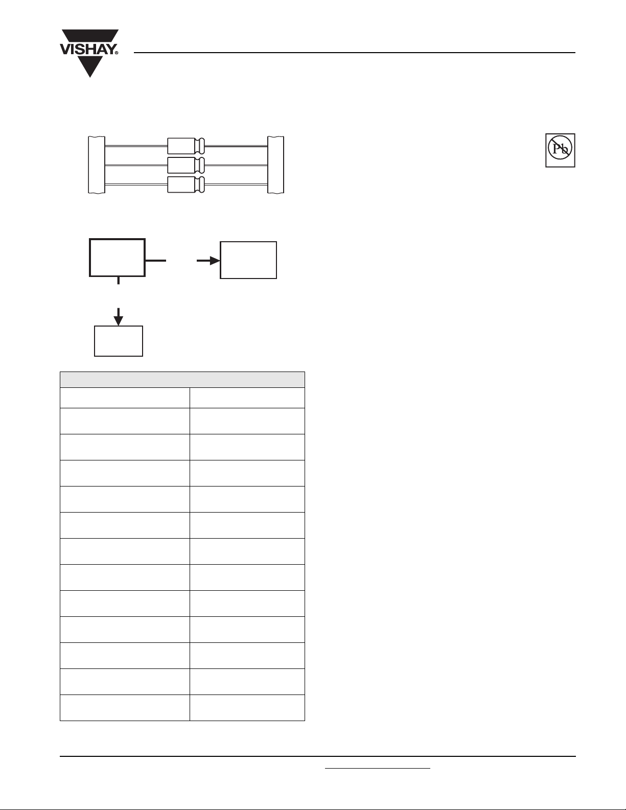
Fig.1 Component outline
123
SAL-A
175 °C
solid SMD
175 TMP
radial
higher
CV/volume
128
SAL-RPM
QUICK REFERENCE DATA
DESCRIPTION VALUE
Maximum case size
(Ø D x L in mm)
Rated capacitance range
(E6 series), C
Tolerance on C
R
R
6.7 x 15.3 to 12.9 x 32.0
1.0 µF to 1500 µF
± 20 %; ± 10 % on request
• Polarized aluminum electrolytic capacitors, solid
electrolyte MnO
2
• Axial leads, aluminum case, ceramic seal, blue
Pb-free
Available
RoHS*
COMPLIANT
insulation sleeve
• SAL-A: standard version
• SAL-AG: epoxy filled shock-proof version up to 10 000 g
• Extremely long useful life: 20 000 hours at 125 °C
• Extended high temperature range up to 200 °C
• Excellent low temperature impedance and ESR behaviour
• Charge and discharge proof, application with
0 Ω resistance allowed
• Reverse DC voltage up to 0.3 x UR allowed
• AC voltage up to 0.8 x U
allowed
R
• Advanced technology to achieve high reliability and high
stability
APPLICATIONS
• EDP, telecommunication, industrial high temperature,
automotive, military and space
• Smoothing, filtering, buffering, timing
• For power supplies, DC/DC converters
Rated voltage range, U
Category temperature range - 55 °C to + 125 °C
R
6.3 V to 40 V
MARKING
The capacitors are marked (where possible) with the
following information:
Usable temperature range - 80 °C to + 200 °C
Endurance test at 155 °C
and 125 °C
Useful life at 125 °C 20 000 hours
Useful life at 40 °C, I
applied 450 000 hours
R
5000 hours and 8000 hours
• Rated capacitance (in µF)
• Tolerance code on rated capacitance, code letter in
accordance with IEC 60062 (M = ± 20 %, K = ± 10 %)
• Rated voltage (in V) at corresponding maximum
temperature
• Date code in accordance with IEC 60062
• Name of manufacturer
Shelf life at 0 V, 125 °C 500 hours
Based on sectional specification IEC 60384-4/EN130300
• Code for factory of origin
• Band to indicate the negative terminal
• ‘+’ sign to identify the positive terminal
Climatic category IEC 60068 55/125/56
* Pb containing terminations are not RoHS compliant, exemptions may apply
Document Number: 28355 For technical questions, contact: aluminumcaps2@vishay.com
Revision: 23-Jun-08 251
• Series number
www.vishay.com
Page 3
123 SAL-A
Vishay BCcomponents
Aluminum Capacitors
Solid Axial
SELECTION CHART FOR CR, UR AND RELEVANT MAXIMUM CASE SIZES (Ø D x L in mm)
(V) at T
U
C
R
(µF)
1.0 - - - - 6.7 x 15.3 -
1.5 - - - - 6.7 x 15.3 -
2.2 - - - - 6.7 x 15.3 6.7 x 15.3
3.3 - - - - 6.7 x 15.3 6.7 x 15.3
4.7 - - - - 6.7 x 15.3 6.7 x 15.3
6.8 - - - - 6.7 x 15.3 6.7 x 15.3
10 - - 6.7 x 15.3 6.7 x 15.3 7.6 x 20.4 7.6 x 20.4
15 - - 6.7 x 15.3 6.7 x 15.3 7.6 x 20.4 7.6 x 20.4
22 - - 6.7 x 15.3 7.6 x 20.4 7.6 x 20.4 9.4 x 23.3
33 - 6.7 x 15.3 7.6 x 20.4 7.6 x 20.4 9.4 x 23.3 9.4 x 23.3
47 6.7 x 15.3 6.7 x 15.3 7.6 x 20.4 7.6 x 20.4 9.4 x 23.3 10.3 x 32.0
68 6.7 x 15.3 7.6 x 20.4 7.6 x 20.4 9.4 x 23.3 10.3 x 32.0 10.3 x 32.0
100 - 7.6 x 20.4 9.4 x 23.3 9.4 x 23.3 12.9 x 32.0 12.9 x 32.0
150 7.6 x 20.4 9.4 x 23.3 9.4 x 23.3 10.3 x 32.0 12.9 x 32.0 220 - 9.4 x 23.3 10.3 x 32.0 12.9 x 32.0 - 330 9.4 x 23.3 10.3 x 32.0 10.3 x 32.0 12.9 x 32.0 - 470 - 10.3 x 32.0 12.9 x 32.0 - - -
680 10.3 x 32.0 12.9 x 32.0 12.9 x 32.0 - - 1000 12.9 x 32.0 12.9 x 32.0 ---1500 12.9 x 32.0 - ----
6.31016253540
6.31016252525
R
U
C
(V) at T
amb
amb
=85°C
= 125 °C
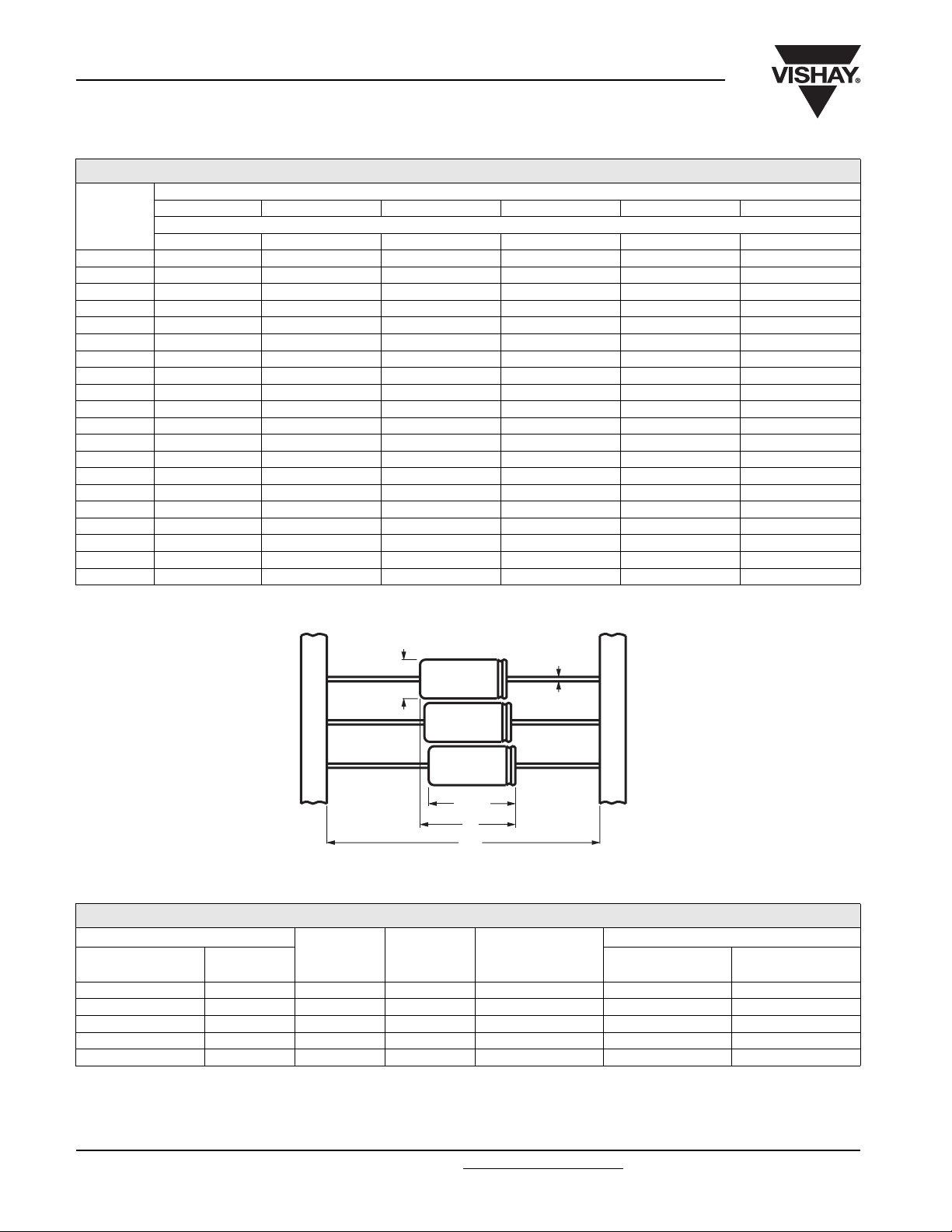
DIMENSIONS in millimeters AND AVAILABLE FORMS
Ø D
Ø d
L
max.
BA: taped in box (ammopack)
BR: taped on reel
F
73
Fig.2 Forms: BA and BR
Tab l e 1
DIMENSIONS in millimeters, MASS AND PACKAGING QUANTITIES
CASE
MAXIMUM SIZE
Ø D x L
10.3 x 32.0 5 35.0 0.8 ≈ 4.2 100 500
12.9 x 32.0 6 35.0 0.8 ≈ 7 100 400
Note
For epoxy-filled versions add 1 mm to stated L
Add 10 % for SAL-AG epoxy-filled versions.
Detailed tape dimensions see section ‘PACKAGING’.
www.vishay.com For technical questions, contact: aluminumcaps2@vishay.com
252 Revision: 23-Jun-08
(1)
6.7 x 15.3 1 20.0 0.6 ≈ 1.05 100 800
7.6 x 20.4 2A 22.5 0.6 ≈ 1.55 100 800
9.4 x 23.3 4 25.0 0.6 ≈ 2.6 100 500
CODE
F
max.
max
Ø d
.
MASS
(g)
(2)
PACKAGING QUANTITIES
FORM
BA
Document Number: 28355
FORM
BR
Page 4
123 SAL-A
Aluminum Capacitors
Solid Axial
ELECTRICAL DATA
SYMBOL DESCRIPTION
C
R
I
R
I
L5
tan δ max. dissipation factor at 100 Hz
ESR max./typ. equivalent series resistance at 100 Hz
Z max. impedance at 100 kHz
Note
Unless otherwise specified, all electrical values in Table 2 apply at
T
= 20 to 25 °C, P = 86 to 106 kPa, RH = 45 to 75 %.
amb
Tab l e 2
rated capacitance at 100 Hz
max. RMS ripple current, no necessary DC voltage
applied
max. leakage current after 5 minutes at U
R
ELECTRICAL DATA AND ORDERING INFORMATION for 123 series
U
U
C
(V)
(V)
6.3 6.3
10 10
16 16
25 25
R
MAX.
CASE SIZE
Ø
D x L
(mm)
C
R
100 Hz
(µF)
47 6.7 x 15.3 58 440 640 15 0.18 7.6 3.0 1.2 13479 23479 83479 63479
68 6.7 x 15.3 83 520 760 21 0.18 5.3 2.6 1.2 13689 23689 83689 63689
150 7.6 x 20.4 160 870 1 270 47 0.18 2.4 1.5 1.0 13151 23151 83151 63151
330 9.4 x 23.3 330 1470 2140 104 0.18 1.1 0.55 0.4 13331 23331 83331 63331
680 10.3 x 32.0 680 2340 3410 214 0.18 0.55 0.28 0.3 13681 23681 83681 63681
1000 12.9 x 32.0 940 3180 4640 315 0.18 0.36 0.19 0.2 13102 23102 83102 63102
1500 12.9 x 32.0 1220 4140 6020 473 0.18 0.24 0.13 0.2 13152 23152 83152 63152
33 6.7 x 15.3 63 360 530 17 0.18 11 3.8 1.2 14339 24339 84339 64339
47 6.7 x 15.3 83 440 640 24 0.18 7.6 4.0 1.2 14479 24479 84479 64479
68 7.6 x 20.4 110 590 850 34 0.18 5.3 2.5 1.0 14689 24689 84689 64689
100 7.6 x 20.4 160 710 1040 50 0.18 3.6 1.8 1.0 14101 24101 84101 64101
150 9.4 x 23.3 240 990 1450 75 0.18 2.4 0.9 0.4 14151 24151 84151 64151
220 9.4 x 23.3 350 1180 1720 110 0.18 1.7 0.6 0.4 14221 24221 84221 64221
330 10.3 x 32.0 490 1650 2410 165 0.18 1.1 0.45 0.3 14331 24331 84331 64331
470 10.3 x 32.0 570 1940 2830 235 0.18 0.8 0.35 0.3 14471 24471 84471 64471
680 12.9 x 32.0 760 2580 3750 340 0.18 0.55 0.25 0.2 14681 24681 84681 64681
1000 12.9 x 32.0 1000 3380 4920 500 0.18 0.36 0.18 0.2 14102 24102 84102 64102
10 6.7 x 15.3 31 230 330 16 0.14 28 8.0 2.5 15109 25109 85109 65109
15 6.7 x 15.3 47 280 400 24 0.14 19 5.5 2.5 15159 25159 85159 65159
22 6.7 x 15.3 63 340 490 35 0.14 13 5.5 2.5 15229 25229 85229 65229
33 7.6 x 20.4 89 470 680 55 0.14 8.4 3.0 2.0 15339 25339 85339 65339
47 7.6 x 20.4 120 560 810 75 0.14 5.9 2.6 2.0 15479 25479 85479 65479
68 7.6 x 20.4 180 670 970 110 0.14 4.1 2.5 2.0 15689 25689 85689 65689
100 9.4 x 23.3 260 920 1340 160 0.14 2.8 1.5 0.8 15101 25101 85101 65101
150 9.4 x 23.3 310 1060 1550 240 0.16 2.1 0.7 0.8 15151 25151 85151 65151
220 10.3 x 32.0 420 1420 2060 350 0.16 1.5 0.55 0.6 15221 25221 85221 65221
330 10.3 x 32.0 510 1740 2530 500 0.16 1.0 0.35 0.6 15331 25331 85331 65331
470 12.9 x 32.0 680 2280 3330 750 0.16 0.7 0.25 0.4 15471 25471 85471 65471
680 12.9 x 32.0 850 2870 4170 870 0.16 0.5 0.18 0.4 15681 25681 85681 65681
10 6.7 x 15.3 43 230 330 25 0.14 28 13.0 5 16109 26109 86109 66109
15 6.7 x 15.3 60 280 400 35 0.14 19 10.0 5.0 16159 26159 86159 66159
22 7.6 x 20.4 88 370 550 55 0.14 13 7 2.5 16229 26229 86229 66229
33 7.6 x 20.4 130 470 680 85 0.14 8.4 5 2.5 16339 26339 86339 66339
47 7.6 x 20.4 160 560 810 100 0.14 5.9 3.5 2.5 16479 26479 86479 66479
68 9.4 x 23.3 230 760 1110 170 0.14 4.1 1.8 1.0 16689 26689 86689 66689
100 9.4 x 23.3 250 860 1250 250 0.16 3.2 1.0 1.0 16101 26101 86101 66101
150 10.3 x 32.0 350 1200 1740 400 0.16 2.1 1.2 0.8 16151 26151 86151 66151
220 12.9 x 32.0 460 1560 2270 550 0.16 1.5 0.85 0.6 16221 26221 86221 66221
330 12.9 x 32.0 600 2030 2950 800 0.16 1.0 0.60 0.6 16331 26331 86331 66331
I
100 Hz
125 °C
(mA)
I
R
R
10 kHz
85 °C
(mA)
I
R
100 kHz
40 °C
(mA)
I
L5
5min
(µA)
ORDERING EXAMPLE
Electrolytic capacitors 123 series
10 µF/16 V; ± 20 %
Maximum case size: Ø 6.7 x 15.3 mm; Form BR
for lead (Pb)-free:
Ordering code: MAL2123 25109E3
Former 12NC: 2281123 25109
for non lead (Pb)-free:
Ordering code: MAL2123 25109
Former 12NC: 2222123 25109
tan
100 Hz
δ
MAX.
ESR
100 Hz
TYP.
ESR
100 Hz
(
Ω
(
)
Ω
)
Vishay BCcomponents
ORDERING CODE
MAL2123.....E3 Lead (Pb)-free
MAL2123 ..... Non lead (Pb)-free
Z
100 kHz
Ω
)
(
SAL-A
FORM
± 20 %
BA
tol.
SAL-A
FORM
BR
tol.
± 20 %
± 10 %
level S
SAL-
(1)
AG
FORM
BA
tol.
SAL-
(1)
AG
FORM
BA
tol.
± 20 %
Document Number: 28355 For technical questions, contact: aluminumcaps2@vishay.com
Revision: 23-Jun-08 253
www.vishay.com
Page 5

123 SAL-A
Vishay BCcomponents
Aluminum Capacitors
Solid Axial
ELECTRICAL DATA AND ORDERING INFORMATION for 123 series
U
(V)
C
U
C
R
100 Hz
(V)
(µF)
R
MAX.
CASE SIZE
Ø
D x L
(mm)
1.0 6.7 x 15.3 4 55 80 5 0.12 240 105 16.5 10108 20108 80108 60108
1.5 6.7 x 15.3 7 68 98 5 0.12 160 40.60 11.0 10158 20158 80158 60158
2.2 6.7 x 15.3 10 82 120 5 0.12 109 30 7.5 10228 20228 80228 60228
3.3 6.7 x 15.3 14 100 150 7 0.12 73 28 7.5 10338 20338 80338 60338
4.7 6.7 x 15.3 20 120 170 10 0.12 51 20 7.5 10478 20478 80478 60478
6.8 6.7 x 15.3 27 140 210 15 0.12 35 16 7.5 10688 20688 80688 60688
25 35
10 7.6 x 20.4 37 200 280 20 0.12 24 10 2.5 10109 20109 80109 60109
15 7.6 x 20.4 53 240 350 30 0.12 16 8 2.5 10159 20159 80159 60159
22 7.6 x 20.4 78 290 420 45 0.12 11 7 2.5 10229 20229 80229 60229
33 9.4 x 23.3 120 410 590 65 0.12 7.2 3 1.0 10339 20339 80339 60339
47 9.4 x 23.3 140 480 700 95 0.12 5.1 2.9 1.0 10479 20479 80479 60479
68 10.3 x 32.0 170 570 820 135 0.16 4.7 2.1 0.8 10689 20689 80689 60689
100 12.9 x 32.0 220 760 1100 200 0.16 3.2 1.7 0.6 10101 20101 80101 60101
150 12.9 x 32.0 290 990 1440 300 0.16 2.1 1.0 0.6 10151 20151 80151 60151
2.2 6.7 x 15.3 11 82 120 9 0.12 109 38 7.5 17228 27228 87228 67228
3.3 6.7 x 15.3 16 100 150 13 0.12 73 25 7.5 17338 27338 87338 67338
4.7 6.7 x 15.3 22 120 170 19 0.12 51 20 7.5 17478 27478 87478 67478
6.8 6.7 x 15.3 28 140 210 27 0.12 35 15 7.5 17688 27688 87688 67688
25 40
10 7.6 x 20.4 41 200 280 40 0.12 24 11 2.5 17109 27109 87109 67109
15 7.6 x 20.4 61 240 350 60 0.12 16 7 2.5 17159 27159 87159 67159
22 9.4 x 23.3 89 330 480 90 0.12 11 4 1.5 17229 27229 87229 67229
33 9.4 x 23.3 120 410 590 130 0.12 7.2 2.9 1.0 17339 27339 87339 67339
47 10.3 x 32.0 160 540 790 190 0.12 5.1 2.7 1.0 17479 27479 87479 67479
68 10.3 x 32.0 170 570 820 270 0.16 4.7 2.3 0.8 17689 27689 87689 67689
100 12.9 x 32.0 220 760 1100 400 0.16 3.2 1.6 0.6 17101 27101 87101 67101
Note
SAL-AG types are epoxy-filled.
I
100 Hz
125 °C
(mA)
I
R
R
10 kHz
85 °C
(mA)
I
R
100 kHz
40 °C
(mA)
I
L5
5min
(µA)
tan
100 Hz
δ
MAX.
ESR
100 Hz
(
Ω
)
TYP.
ESR
100 Hz
(
Ω
)
Z
100 kHz
Ω
)
(
ORDERING CODE
MAL2123.....E3 Lead (Pb)-free
MAL2123 ..... Non lead (Pb)-free
SAL-
SAL-A
FORM
BA
tol.
± 20 %
SAL-A
FORM
BR
tol.
± 20 %
(1)
AG
FORM
BA
tol.
± 10 %
level S
FORM
± 20 %
SALAG
BA
tol.
(1)
ADDITIONAL ELECTRICAL DATA
PARAMETER CONDITIONS VALUE
Voltag e
Surge voltage U
Reverse voltage U
Maximum peak AC voltage, reverse
voltage applied
T
≤ 85 °C:
amb
at f ≤ 0.1 Hz 0.30 x U
at 0.1 Hz < f ≤ 1Hz 0.45xU
at 1 Hz < f ≤ 10 Hz 0.60 x U
at 10 Hz < f ≤ 50 Hz 0.65 x U
Maximum peak AC voltage, without
reverse voltage applied
at f > 50 Hz 0.80 x U
85 °C < T
amb
≤ 125 °C:
at f ≤ 0.1 Hz 0.15 x U
at 0.1 Hz < f ≤ 1Hz 0.22xU
at 1 Hz < f ≤ 10 Hz 0.30 x U
at 10 Hz < f ≤ 50 Hz 0.32 x U
at f > 50 Hz 0.40 x U
Current
Maximum leakage current After 5 minutes at U
Typical leakage current
After 15 s at U
U
= 6.3 to 16 V ≈ 0.2 x value stated in Table 2
R
U
= 25 to 40 V ≈ 0.1 x value stated in Table 2
R
and T
R
and T
R
amb
=25°C
amb
=25°C:
www.vishay.com For technical questions, contact: aluminumcaps2@vishay.com
254 Revision: 23-Jun-08
≤ 1.15 x U
s
< 0.3 x U
rev
R
R
≤ 2V
R
R
R
R
R
R
R
R
R
R
I
≤ 0.05 CR x UR or 2 µA, whichever is greater;
L5
see Table 2
Document Number: 28355
Page 6

123 SAL-A
40
VOL TAGE
(1)
UC = 125 °C
35
(2)
R
25
16
10
6.3
4
0
- 50
UC = 175 °C
0
U
(V)
Fig.3 Maximum permissible voltage up to 175 °C
LEAKAGE CURRENT
2
10
I
I
01
10
50
85
100
Aluminum Capacitors
Solid Axial
(1) (2)
150 175
125
(°C)
T
amb
Vishay BCcomponents
RIPPLE CURRENT (IR)
T
PARAMETER
I
multiplier 1.1 1.0 0.88 0.75 0.59 0.37
R
25 °C 40 °C 65 °C 85 °C 105 °C 125 °C
Notes
(1)
Applying the maximum RMS ripple current given in Table 2
will cause a device temperature of 138 °C.
(2)
The 100 kHz values in Table 2 for other temperatures are to
be calculated with the above I
10
reverse voltage
I
I
02
amb
multipliers.
R
1
1
I01 = leakage current during continuous operation
at U
and T
10
R
-1
amb
0
= 25 °C
100
T
amb
Fig.4 Typical multiplier of leakage current as a function of
(°C)
150 - 50 50
I02 = leakage current at UR at a
discrete constant temperature
-1
10
0.8 - 0.4 0 0.4
U
U
R
Fig.5 Typical multiplier of leakage current as a function of U/U
R
ambient temperature
CAPACITANCE (C)
1.1
C
C
0
1.0
0.9
0.8
C0 = capacitance at 25 °C and 100 Hz
- 80 - 40 40
0
σ
80 120 160 200
T
amb
σ
standard deviation
0.05
0
(°C)
DISSIPATION FACTOR (tan δ)
2.4
tan δ
tan δ
0
2.0
1.6
1.2
0.8
0.4
0
- 80 - 40 40
Typical tan δ at 100 Hz and T
0.6 x value stated in Table 2
σ
0
80 120 160 200
= 25 °C:
amb
T
amb
σ
standard deviation
0.25
0
(°C)
Fig.6 Typical multiplier of capacitance as a function
of ambient temperature
Fig.7 Typical multiplier of dissipation factor as a function of
ambient temperature
Document Number: 28355 For technical questions, contact: aluminumcaps2@vishay.com
www.vishay.com
Revision: 23-Jun-08 255
Page 7

123 SAL-A
Vishay BCcomponents
Aluminum Capacitors
Solid Axial
MAXIMUM POWER DISSIPATION
MAXIMUM CASE SIZE
Ø D x L
(mm)
6.7 x 15.3 0.13
7.6 x 20.4 0.16
9.4 x 23.3 0.21
10.3 x 32.0 0.26
12.9 x 32.0 0.32
EQUIVALENT SERIES INDUCTANCE (ESL), f=10MHz
MAXIMUM CASE SIZE
Ø D x L
(mm)
6.7 x 15.3 20.3 30 15 to 23
7.6 x 20.4 25.4 30 16 to 24
9.4 x 23.3 27.9 35 20 to 27
10.3 x 32.0 35.6 40 26 to 33
12.9 x 32.0 35.6 55 32 to 49
IMPEDANCE (Z)
Typical impedance at 100 kHz and T
= 25 °C: 0.5 x value stated in Table 2.
amb
PITCH
(mm)
P
max.=P125
(W)
MAX. ESL
(nH)
TYP. ESL
(nH)
3.5
Z
Z
0
3.0
2.5
2.0
1.5
1.0
0.5
0
10
1 4 7 10 10 3
Curve 1: case Ø D x L = 6.7 x 15.3 and 7.6 x 20.4 mm; 16 to 40 V
Curve2: case Ø D x L=6.7 x 15.3and7.6 x 20.4mm;6.3to10V
Curve 3: case Ø D x L = 9.4 x 32.0, 10.3 x 32.0 and 12.9 x 32.0 mm
Z
= initial impedance value at any frequency and T
0
10
1
amb
2
=25°C
- 55 °C
- 25 °C
+ 25 °C
+ 85 °C
+ 175 °C
3
10
10
1
2
3
1
2
3
3
2
3
2
1
4
1
5
10
standard deviation
10
6
f (Hz)
σ
10
(% )
7
Fig.9 Typical multiplier of impedance as a function of frequency at different ambient temperatures
www.vishay.com For technical questions, contact: aluminumcaps2@vishay.com
Document Number: 28355
256 Revision: 23-Jun-08
Page 8

123 SAL-A
IMPEDANCE (Z)
3
10
Z
Ω
( )
2
10
1
2
3
4
5
6
10
1
Case Ø D x L = 6.7 x 15.3 mm; UR = 6.3 to 16 V
-1
10
10 10
2
103 10
Fig.10 Typical impedance as a function of frequency
3
10
Z
Ω
( )
2
10
10
1
2
3
4
5
Curve 1: 10 µF, 16 V
Curve 2: 15 µF, 16 V
Curve 3: 22 µF, 16 V
Curve 4: 33 µF, 10 V
Curve 5: 47 µF, 6.3 and 10 V
Curve 6: 68 µF, 6.3 V
4 105
Curve 1: 33 µF, 16 V
Curve 2: 47 µF, 16 V
Curve 3: 68 µF, 10 V
Curve 4: 100 µF, 6.3 and 10 V
Curve 5: 150 µF, 6.3 V
Aluminum Capacitors
Solid Axial
4
10
Z
Ω
( )
3
10
2
10
10
( )
Z
Ω
1
10
10
10
3
2
10 10
106 10
f (Hz)
T
= 25 °C
amb
7
Vishay BCcomponents
Curve 1: 2.2 µF, 35 and 40 V
Curve 2: 3.3 µF, 40V
1
2
3
4
5
6
Case Ø D x L = 6.7 x 15.3 mm;
UR = 25 to 40 V
2
103 10
Fig.11 Typical impedance as a function of frequency
1
2
3
4
5
6
Curve 3: 4.7 µF, 35 and 40 V
Curve 4: 6.8 µF, 35 and 40 V
Curve 5: 10 µF, 25 V
Curve 6: 15 µF, 25 V
4 105
106 10
T
amb
Curve 1: 10 µF, 35 and 40 V
Curve 2: 15 µF, 35 and 40 V
Curve 3: 22 µF, 25 and 40 V
Curve 4: 33 µF, 25 V
Curve 5: 47 µF, 25 V
Curve 6: 68 µF, 16 V
f (Hz)
= 25 °C
7
1
Case Ø D x L = 6.7 x 20.4 mm
UR = 6.3 to 16 V
-1
10
10 10
2
103 10
4 105
Fig.12 Typical impedance as a function of frequency
2
10
Z
Ω
( )
10
1
2
3
1
-1
10
Case Ø D x L = 9.4 x 23.3 mm; UR = 6.3 to 10 V
-2
10
10 10
2
103 10
4 105 106
Fig.14 Typical impedance as a function of frequency
106 10
f (Hz)
T
= 25 °C
amb
Curve 1: 150V, 10 V
Curve 2: 220 V, 10V
Curve 3: 330 V, 6.3 V
10
f (Hz)
T
= 25 °C
amb
7
7
1
Case Ø D x L = 6.7 x 20.4 mm; UR = 16 to 40 V
-1
10
10 10
2
103 10
4 105
Fig.13 Typical impedance as a function of frequency
3
( )
10
Z
Ω
Curve 1: 22 µF, 40 V
Curve 2: 33 µF, 35 and 40 V
Curve 3: 47 µF, 35 V
2
10
10
1
2
3
4
5
6
Curve 4: 68 µF, 25 V
Curve 5: 100 µF, 16 and 25 V
Curve 6: 150 µF, 1 6 V
1
Case Ø D x L = 9.4 x 23.3 mm;
= 16 to 40 V
U
-1
R
10
10 10
2
103 10
4 105 106
Fig.15 Typical impedance as a function of frequency
106 10
f (Hz)
= 25 °C
T
amb
10
f (Hz)
T
= 25 °C
amb
Document Number: 28355 For technical questions, contact: aluminumcaps2@vishay.com
www.vishay.com
Revision: 23-Jun-08 257
7
7
Page 9

123 SAL-A
Vishay BCcomponents
IMPEDANCE (Z)
2
10
Z
Ω
( )
1
2
3
4
5
Case Ø D x L = 10.3 x 32.0 mm; UR = 6.3 to 16 V
2
103 10
4 105 106
Fig.16 Typical impedance as a function of frequency
Curve 1: 680 µF, 10 V
Curve 2: 1000 µF, 6.3 V
Curve 3: 1500 µF, 6.3 V
1
2
3
(Ω)
10
1
10
10
10
Z
10
1
-1
-2
10 10
2
Aluminum Capacitors
Curve 1: 220 µF, 16 V
Curve 2: 330 µF, 16 V
Curve 3: 330 µF, 10 V
Curve 4: 470 µF, 10 V
Curve 5: 680 µF, 6.3 V
10
f (Hz)
T
= 25 °C
amb
Solid Axial
3
10
Z
Ω
( )
2
10
10
1
-1
10
7
2
10
Z
(Ω)
10
1
Curve 1: 47 V, 40 V
Curve 2: 68 V, 35 and 40 V
Curve 3: 150 V, 25 V
1
2
3
Case Ø D x L = 10.3 x 32.0 mm;
UR = 25 to 40 V
10 10
2
103 10
4 105 106
T
Fig.17 Typical impedance as a function of frequency
Curve 1: 100 µF, 35 and 40 V
1
2
3
4
5
6
Curve 2: 150 µF, 3 5 V
Curve 3: 220 µF, 2 5 V
Curve 4: 470 µF, 1 6 V
Curve 5: 680 µF, 1 6 V
Curve 6: 1000 µF, 10 V
10
f (Hz)
= 25 °C
amb
7
-1
10
Case Ø D x L = 12.9 x 32.0 mm; UR = 6.3 to 10 V
-2
10
2
10
3
10
4
10
5
10
Fig.18 Typical impedance as a function of frequency
= 25 °C
7
10
6
10
f (Hz)
T
amb
-1
10
Case Ø D x L = 12.9 x 32.0 mm; UR = 10 to 40V
-2
10
2
10
3
10
4
10
5
10
Fig.19 Typical impedance as a function of frequency
6
10
T
f (Hz)
amb
10
= 25 °C
EQUIVALENT SERIES RESISTANCE (ESR)
Typical ESR: see Figs to 24; the standard deviation is 20 % of each value.
2
10
Case Ø D x L = 6.7 x 15.3 mm
ESR
(Ω)
10
1
Curve 1: 10 mF, 25 V; 6.8 mF, 35 and 40 V
ESR at 100 Hz
1
3
2
4
5
Curve 2: 10 mF, 16 V
Curve 3: 22 mF, 16 V
Curve 4: 33 mF, 10 V
Curve 5: 47 mF, 6.3 and 10 V; 68 mF, 6.3 V
-1
10
- 80
0 80- 40 120 160 200
40
T
amb
(°C)
Fig.20 Typical ESR as a function of ambient temperature
www.vishay.com For technical questions, contact: aluminumcaps2@vishay.com
258 Revision: 23-Jun-08
2
10
Case Ø D x L = 7.6 x 20.4 mm
ESR
(Ω)
ESR at 100 Hz
10
1
Curve 1: 10 µF, 35 and 40 V
Curve 2: 33 µF, 25 V
Curve 3: 47 µF, 25 V
Curve 4: 68 µF, 10 V; 150 µF, 6.3 V
-1
10
- 80
0 80- 40 120 160 200
40
Fig.21 Typical ESR as a function of ambient temperature
Document Number: 28355
1
2
3
4
5
(°C)
T
amb
7
Page 10

123 SAL-A
Aluminum Capacitors
Solid Axial
EQUIVALENT SERIES RESISTANCE (ESR)
2
10
ESR
(Ω)
10
1
Case Ø D x L = 9.4 x 23.3 mm
-1
10
- 80
Fig.22 Typical ESR as a function of ambient temperature
2
10
Case Ø D x L = 12.9 x 32.0 mm
ESR at 100 Hz
ESR
(Ω)
10
Curve 1: 33 µF, 35 and 40 V
Curve 2: 220 µF, 10 V; 330 µF, 6.3 V
1
2
ESR at 100 Hz
0 80- 40 120 160 200
40
T
amb
Curve 1: 100 µF, 35 and 40 V
Curve 2: 150 µF, 3 5 V
Curve 3: 220 µF, 2 5 V
Curve 4: 470 µF, 1 6 V
Curve 5: 680 µF, 1 0 V;
1000 µF, 6.3 V
(°C)
Vishay BCcomponents
2
10
Case Ø D x L = 10.3 x 32.0 mm
ESR
ESR at 100 Hz
(Ω)
10
1
-1
10
- 80
0 80- 40 120 160 200
Fig.23 Typical ESR as a function of ambient temperature
3
10
ESR
(Ω)
10
10
1
2
2
3
4
5
Curve 1: 10 µF, 25 V; 6.8 µF, 35 and 40 V
Curve 2: 10 µF, 16 V
Curve 3: 22 µF, 16 V
Curve 4: 33 µF, 10 V
Curve 5: 47 µF, 6.3 and 10 V; 68 µF, 6.3 V
Curve 1: 68 µF, 35 and 40 V
Curve 2: 150 µF, 2 5 V
Curve 3: 330 µF, 1 0 V
Curve 4: 470 µF, 1 0 V
40
1
2
3
4
(°C)
T
amb
1
-1
10
- 80
0 80- 40 120 160 200
40
Fig.24 Typical ESR as a function of ambient temperature
3
10
ESR
(Ω)
1
2
10
10
1
10
2
3
4
5
Case Ø D x L = 6.7 x 20.4 mm
-1
1
10
10
Curve 1: 10 µF, 35 and 40 V
Curve 2: 33 µF, 2 5 V
Curve 3: 47 µF, 2 5 V
Curve 4: 68 µF, 1 0 V; 150 µF, 6.3 V
Curve 5: 100 µF, 1 0 V
2
3
10
4
10
Fig.26 Typical ESR as a function of frequency
10
T
5
amb
T
f (Hz)
1
2
3
4
5
(°C)
amb
= 25 °C
6
10
1
Case Ø D x L = 6.7 x 15.3 mm
-1
10
2
1
10
10
3
10
Fig.25 Typical ESR as a function of frequency
2
10
ESR
(Ω)
Curve 1: 33 µF, 35 and 40 V
Curve 2: 220 µF, 1 0 V; 330 µF, 6.3 V
10
1
-1
10
Case Ø D x L = 9.4 x 23.3 mm
-2
10
2
1
10
10
3
10
Fig.27 Typical ESR as a function of frequency
10
T
5
amb
f (Hz)
10
= 25 °C
4
10
1
2
10
T
5
amb
f (Hz)
10
= 25 °C
4
10
Document Number: 28355 For technical questions, contact: aluminumcaps2@vishay.com
www.vishay.com
Revision: 23-Jun-08 259
6
6
Page 11

123 SAL-A
Vishay BCcomponents
Aluminum Capacitors
Solid Axial
EQUIVALENT SERIES RESISTANCE (ESR)
2
10
ESR
(Ω)
1
10
2
3
4
1
-1
10
Case Ø D x L = 9.4 x 23.3 mm
-2
10
1
10
2
10
Curve 1: 68 µF, 35 and 40 V
Curve 2: 150 µF, 25 V
Curve 3: 330 µF, 10 V
Curve 4: 470 µF, 10 V
ESR at 100 Hz
3
10
4
10
5
10
f (Hz)
6
10
Fig.28 Typical ESR as a function of ambient temperature
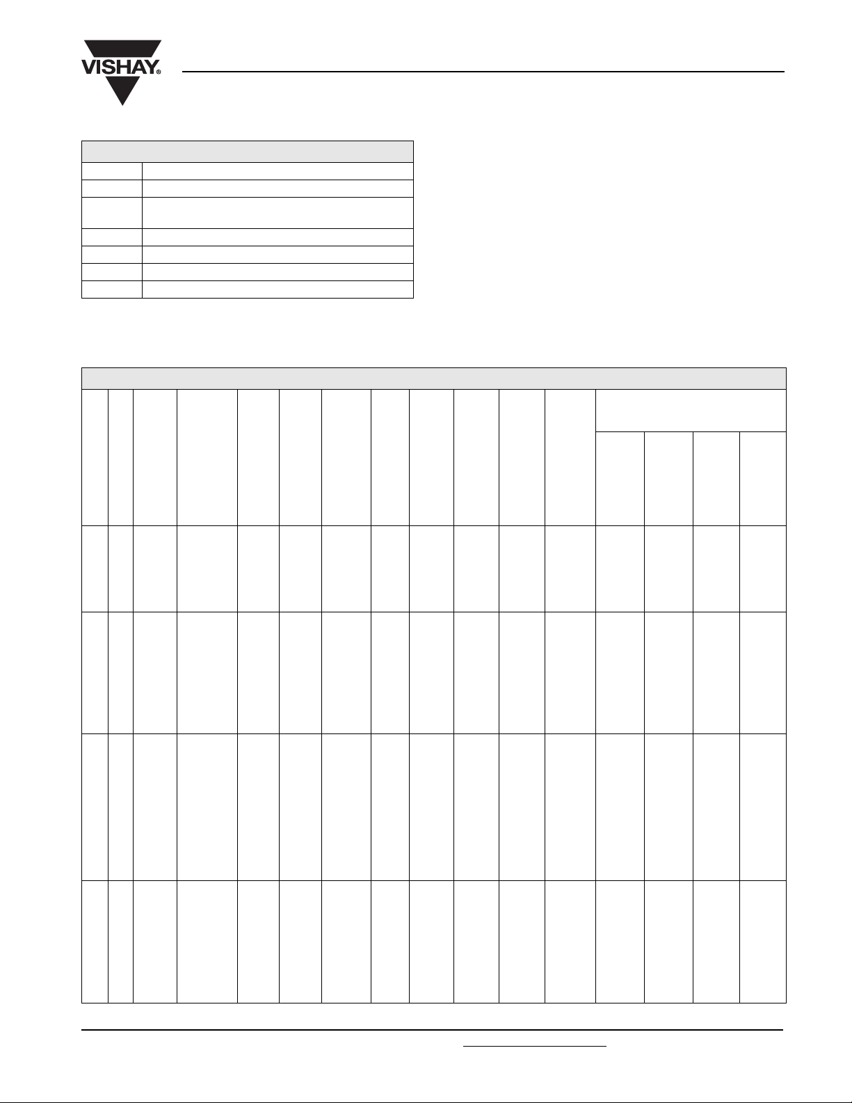
Tab l e 3
TEST PROCEDURES AND REQUIREMENTS
TEST
NAME OF TEST REFERENCE
Endurance IEC 60384-4/
EN130300
subclause 4.13
Useful life CECC 30302
subclause 1.8.1
Shelf life
(storage at high
temperature)
Charge and
discharge
IEC 60384-4/
EN130300
subclause 4.17
IEC 60384-4-2
subclause 9.21
= 125 °C;
T
amb
= 6.3 to 25 V with UR applied;
U
R
= 35 and 40 V with UC applied;
U
R
10 000 hours
= 125 °C; IR applied and
T
amb
= 6.3 to 25 V with UR applied;
U
R
= 35 and 40 V with UC applied;
U
R
20 000 hours
= 125 °C; no voltage applied;
T
amb
500 hours
6
cycles without series resistance:
10
0.5 s to U
0.5 s to ground
Shock IEC 60068-2-27
test Ea
half-sine or saw tooth pulse shape; 50 g; 11 ms;
3 successive shocks in each direction of
3 mutually perpendicular axes;
no voltage applied
Severe rapid change
of temperature
Solvent resistance IEC 60068-2-45,
test XA
IEC 60653
100 cycles of 1 hour duration, each with
30 minutes at - 40 °C and + 125 °C
immersion:
5 ± 0.5 minutes with or without ultrasonic
at 55 ± 5 °C
solvents: demineralized water and/or calgonite
solution (20 g/l)
Passive flammability IEC 60695-2-2 capacitor mounted to a vertical printed-circuit
board, one flame on capacitor body;
=20to25°C;
T
amb
test duration = 20 s
www.vishay.com For technical questions, contact: aluminumcaps2@vishay.com
260 Revision: 23-Jun-08
PROCEDURE
(quick refeerence)
;
R
2
10
ESR
(Ω)
1
2
10
3
4
5
1
-1
10
Case Ø D x L = 9.4 x 23.3 mm
-2
10
1
10
Curve 1: 100 µF, 35 and 40 V
Curve 2: 150 µF, 35 V
Curve 3: 220 µF, 25 V
Curve 4: 470 µF, 16 V
Curve 5: 680 µF, 10 V; 1000 µF, 6.3 V
2
10
3
10
4
10
Fig.29 Typical ESR as a function of ambient temperature
REQUIREMENTS
ΔC/C: ± 10 %
tan δ≤1.2 x spec. limit
Z ≤ 1.2 x spec. limit
≤ spec. limit
I
L5
ΔC/C: ± 15 %
tan δ≤1.5 x spec. limit
Z ≤ 1.5 x spec. limit
≤ spec. limit
I
L5
no short or open circuit,
no visible damage
total failure percentage: < 1 %
ΔC/C: ± 10 %
tan δ≤1.2 x spec. limit
I
≤ 1 x spec. limit
L5
ΔC/C: ± 5 %
no short or open circuit,
no visible damage
no intermittent contacts
no breakdown
no open circuiting
no mechanical damage
ΔC/C: ± 5 %
tan δ≤1.2 x spec. limit
Z ≤ 1.2 x spec. limit
≤ 1.5 x spec. limit
I
L5
ΔC/C: ± 25 %
tan δ≤1.5 x spec. limit
Z ≤ 2.0 x spec. limit
≤ 1 x spec.limit
I
L5
visual appearance not affected
after removing the test flame from the
capacitor, the capacitor must not
continue to burn for more than 15 s;
no burning particles must drop from
the sample
Document Number: 28355
ESR at 100 Hz
5
10
f (Hz)
10
6
Page 12

123 SAL-A
Aluminum Capacitors
Vishay BCcomponents
Solid Axial
ADDITIONAL TESTS AND REQUIREMENTS FOR EPOXY-FILLED VERSIONS SAL-AG
2281 123 8.... Form BA ± 10 %, level S, lead (Pb)-free
2222 123 8.... Form BA ± 10 %, level S, non lead (Pb)-free
Tab l e 4
TEST PROCEDURES AND REQUIREMENTS
TEST PROCEDURE REQUIREMENTS
Severe vibration tests in accordance with “IEC 60 068-2-6” and “MIL STD-202”, method 204, letter E, with the following details and
additions
Method of mounting: clamping both body and leads ΔC/C: ± 10 %
severity 1 frequency range temperature 10 to 3000 Hz; 20 to 25 °C
severity 2 frequency range temperature 50 to 2000 Hz; 125 °C
severity 1 and 2 vibration amplitude: 50 g or 3.5 mm, whichever is less
Direction and duration of motion:
severity 1 1 octave/minute; 3 directions (mutually perpendicular);
20 sweeps per direction (total 60 sweeps or 18 hours)
severity 2 1 octave/minute; 2 directions (longitudinal and
transversal); 3 sweeps per direction
(total 6 sweeps or 1 hour)
Functioning:
tan δ≤1.2 x stated limit
Z ≤ 1.4 x stated limit
DC leakage current: ≤ stated limit
no intermittent contacts
no indication of breakdown
no open circuiting
no evidence of mechanical damage
severity 1 rated voltage applied
severity 2 no voltage applied
Typical capability > 80 g at 10 to 3000 Hz (also at 125 °C)
Severe shock tests in accordance with “IEC 60 068-2-27” and “MIL STD-202”, method 213, letter F, with the following details and
additions:
Method of mounting clamping both body and leads ΔC/C: ± 10 %
Pulse shape: half-sine or sawtooth
severity 1 1500 g; 0.5 ms (“MIL STD-202”, method 213, letter F)
severity 2 3000 g; 0.2 ms
severity 3 10 000 g; 0.1 ms
Direction and number of shocks:
severity 1 and 2 3 successive shocks in each direction of 3 mutually
perpendicular axes (total 18 shocks)
severity 3 1 shock in any direction
Functioning rated voltage applied
tan δ≤1.2 x stated limit
Z ≤ 1.4 x stated limit
DC leakage current: ≤ stated limit
no intermittent contacts
no indication of breakdown
no open circuiting
no evidence of mechanical damage
Document Number: 28355 For technical questions, contact: aluminumcaps2@vishay.com
Revision: 23-Jun-08 261
www.vishay.com
Page 13

Legal Disclaimer Notice
Vishay
Disclaimer
All product specifications and data are subject to change without notice.
Vishay Intertechnology, Inc., its affiliates, agents, and employees, and all persons acting on its or their behalf
(collectively, “Vishay”), disclaim any and all liability for any errors, inaccuracies or incompleteness contained herein
or in any other disclosure relating to any product.
Vishay disclaims any and all liability arising out of the use or application of any product described herein or of any
information provided herein to the maximum extent permitted by law. The product specifications do not expand or
otherwise modify Vishay’s terms and conditions of purchase, including but not limited to the warranty expressed
therein, which apply to these products.
No license, express or implied, by estoppel or otherwise, to any intellectual property rights is granted by this
document or by any conduct of Vishay.
The products shown herein are not designed for use in medical, life-saving, or life-sustaining applications unless
otherwise expressly indicated. Customers using or selling Vishay products not expressly indicated for use in such
applications do so entirely at their own risk and agree to fully indemnify Vishay for any damages arising or resulting
from such use or sale. Please contact authorized Vishay personnel to obtain written terms and conditions regarding
products designed for such applications.
Product names and markings noted herein may be trademarks of their respective owners.
Document Number: 91000 www.vishay.com
Revision: 18-Jul-08 1
 Loading...