

Page 1

6121 Baker Road,
Suite 108
Minnetonka, MN 55345
www.chtechnology.com
Phone (952) 933-6190
Fax (952) 933-6223
1-800-274-4284
Thank you for downloading this document from C&H Technology, Inc.
Please contact the C&H Technology team for the following questions -
Technical
Application
Assembly
Availability
Pricing
Phone – 1-800-274-4284
E-Mail – sales@chtechnology.com
www.chtechnology.com - SPECIALISTS IN POWER ELECTRONIC COMPONENTS AND ASSEMBLIES - www.chtechnology.com
Page 2
093 PMG-SI
Vishay BCcomponents
Power Miniaturized General Purpose Snap-In
Aluminum Capacitors
FEATURES
• Polarized aluminum electrolytic capacitors,
non-solid electrolyte
• Large types, miniaturized dimensions, cylindrical
aluminum case insulated with a blue sleeve
• Useful life: 2000 hours at 85 °C
• Compliant to RoHS directive 2002/95/EC
RoHS
COMPLIANT
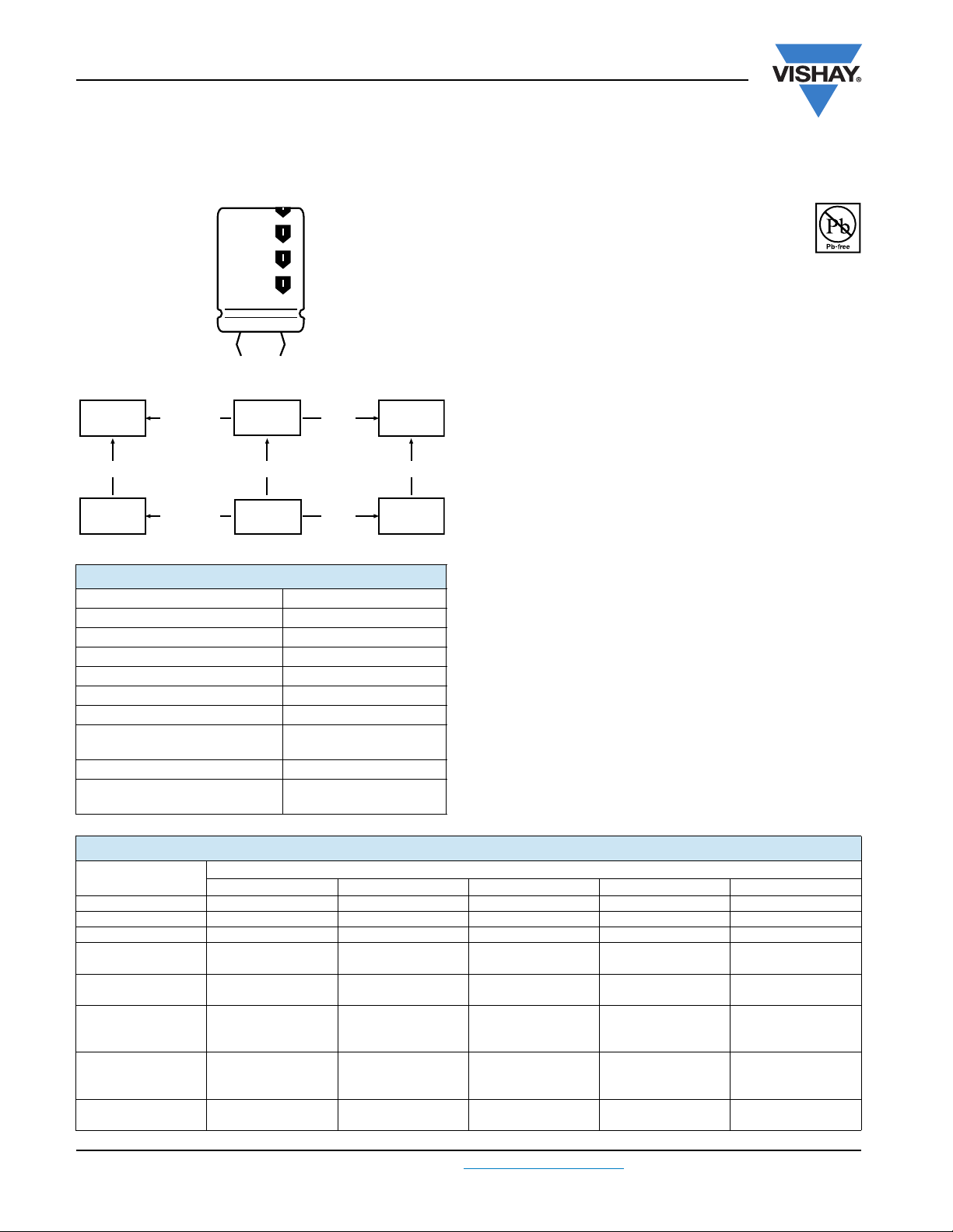
Fig.1 Component outlines
094 199
093
smaller
dimensions
smaller
dimensions
105 °C105 °C
197
longer
life
105 °C
longer
life
QUICK REFERENCE DATA
DESCRIPTION VALUE
Nominal case size (Ø D x L in mm) 22 x 25 to 35 x 50
Rated capacitance range, C
Tolerence on C
Rated voltage range, U
Category temperature range - 25 °C to + 85 °C
Useful life at 85 °C 2000 hours
Useful life at 40 °C and
1.4 x I
R
Shelf life at 0 V, 85 °C 500 hours
Based on sectional specification
R
applied
R
R
68 µF to 2200 µF
± 20 %
200 V to 450 V
36 000 hours
IEC 60384-4/EN130300/W
of JISC5141
159
157
APPLICATIONS
• Consumer electronics
• Whitegood motor control
• Electronic drives
• Smps/ups
MARKING
The capacitors are marked (where possible) with the
following information:
• Rated capacitance (in µF)
• Tolerance on rated capacitance, code letter in accordance
with IEC 60062 (M for ± 20 %)
• Rated voltage (in V)
• Date code
• Name of manufacturer
• ‘-’ sign to identify the negative terminal, visible from the top
and side of the capacitor
• Code number (last 8 digits)
• Maximum operating temperature
SELECTION CHART FOR CR, UR AND RELEVANT NOMINAL CASE SIZES (Ø D x L in mm)
(V)
C
R
(µF)
68 - - 22 x 25 - 82 - - - - 22 x 25
100 - - 22 x 25 22 x 25 22 x 30
120
150 - -
180 - -
220 22 x 25
270 22 x 25 22 x 30
www.vishay.com For technical questions, contact: aluminumcaps2@vishay.com
36 Revision: 04-Dec-09
200 250 400 420 450
-
- 25 x 25
- 25 x 30 25 x 35
---
U
R
22 x 30
22 x 30 25 x 25
22 x 35
25 x 30
22 x 40
30 x 25 30 x 25
22 x 50
30 x 25 35 x 25
22 x 35
25 x 30
25 x 35
30 x 25
22 x 50
30 x 30
Document Number: 28383
22 x 35
22 x 40
25 x 30
30 x 25
22 x 50
30 x 30
Page 3
093 PMG-SI
Aluminum Capacitors
Vishay BCcomponents
Power Miniaturized General Purpose Snap-In
SELECTION CHART FOR CR, UR AND RELEVANT NOMINAL CASE SIZES (Ø D x L in mm)
(V)
C
R
(µF)
330 22 x 35
390
470 22 x 35 25 x 35
560 25 x 30 25 x 40
680 25 x 35 30 x 30 35 x 40 35 x 45 35 x 50
820 25 x 40 30 x 35 35 x 50 - 1000 30 x35 30 x 40 - - 1200 30 x 40 35 x 40 - - 1500 30 x 45 35 x 45 - - -
1800
2200 35 x 45 - - - -
200 250 400 420 450
- 30 x 30
22 x 30
25 x 25
30 x 50
35 x 40 -
22 x 35
25 x 30
35 x 50
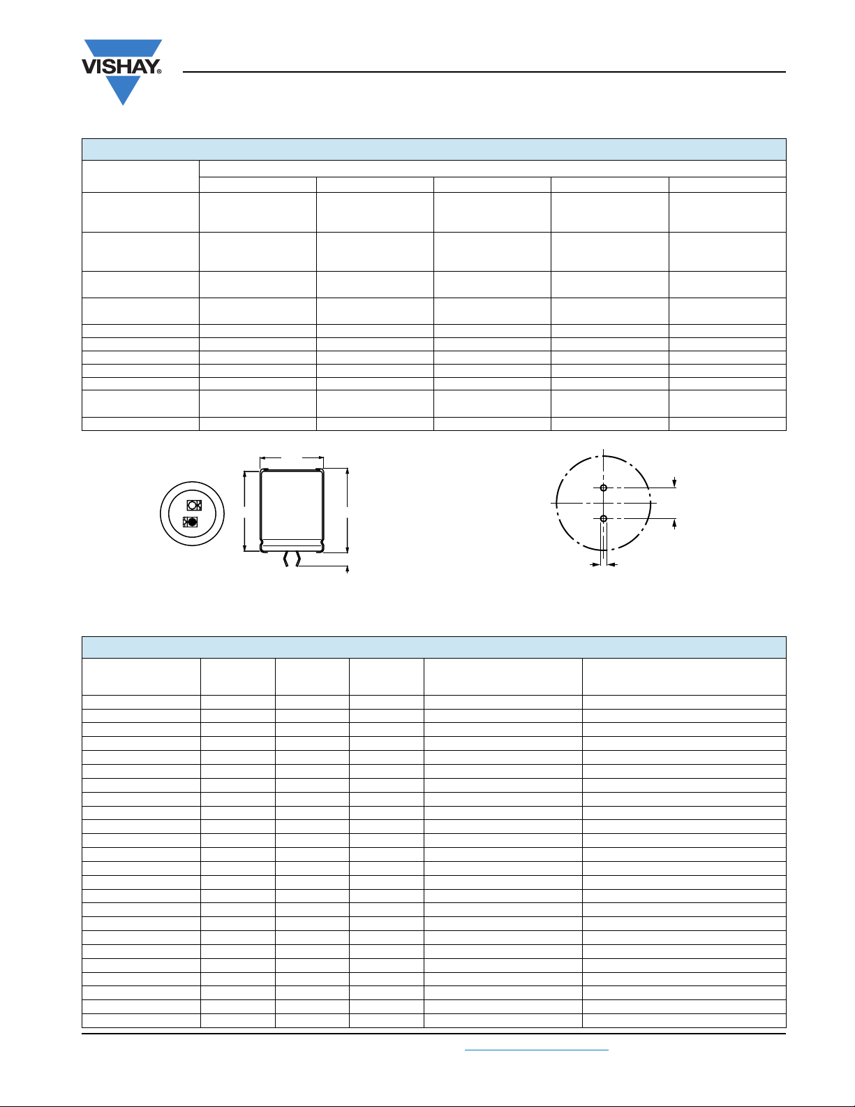
DIMENSIONS in millimeters AND AVAILABLE FORMS
Ø D
U
R
25 x 40
35 x 25
25 x 50
30 x 35
35 x 30
30 x 40
35 x 30
30 x 45 30 x 50
35 x 35 35 x 40
----
25 x 50
30 x 35
35 x 30
35 x 35 35 x 40
25 x 50
35 x 30
30 x 40
35 x 35
35 x 45
-
+ Terminal
- Terminal
Bottom view
The minus and/or plus terminal can be marked with an imprinted sign
Fig.2 Two terminal snap-in
Tab l e 1
L
L + 2 max.
6.3 + 1 mm
Ø 2 ± 0.1 (2 ×)
Fig.3 Mounting hole diagram
10
± 0.1
DIMENSIONS in millimeters, MASS AND PACKAGING QUANTITIES
NOMINAL
CASE SIZE
Ø DxL
22 x 25 22.5 26.5 ≈ 12 216 280 x 240 x 140
22 x 30 22.5 31.5 ≈ 16 216 280 x 240 x 140
22 x 35 22.5 36.5 ≈ 20 144 280 x 240 x 105
22 x 40 22.5 41.5 ≈ 23 144 280 x 240 x 105
22 x 45 22.5 46.5 ≈ 26 144 280 x 240 x 140
22 x 50 22.5 51.5 ≈ 29 72 280 x 240 x 105
25 x 25 25.5 26.5 ≈ 20 216 280 x 240 x 140
25 x 30 25.5 33.5 ≈ 22 216 280 x 240 x 140
25 x 35 25.5 36.5 ≈ 24 144 280 x 240 x 105
25 x 40 25.5 41.5 ≈ 27 144 280 x 240 x 105
25 x 45 25.5 46.5 ≈ 32 144 280 x 240 x 140
25 x 50 25.5 51.5 ≈ 38 144 280 x 240 x 140
30 x 25 30.5 28.5 ≈ 25 168 280 x 240 x 140
30 x 30 30.5 33.5 ≈ 30 168 280 x 240 x 140
30 x 35 30.5 38.5 ≈ 35 112 280 x 240 x 105
30 x 40 30.5 42.5 ≈ 40 112 280 x 240 x 105
30 x 45 30.5 47.5 ≈ 45 112 280 x 240 x 140
30 x 50 30.5 52.5 ≈ 50 112 280 x 240 x 140
35 x 25 35.5 26.5 ≈ 33 126 280 x 240 x 140
35 x 30 35.5 33.5 ≈ 40 126 280 x 240 x 140
35 x 35 35.5 36.5 ≈ 48 84 280 x 240 x 105
35 x 40 35.5 42.5 ≈ 55 84 280 x 240 x 105
35 x 45 35.5 47.5 ≈ 63 84 280 x 240 x 140
35 x 50 35.5 52.5 ≈ 72 84 280 x 240 x 140
Document Number: 28383 For technical questions, contact: aluminumcaps2@vishay.com
Revision: 04-Dec-09 37
Ø D
max.
L
max.
MASS
(g)
PACKAGING QUANTITIES
CARDBOARD BOX DIMENSIONS
L x W x H
www.vishay.com
Page 4

093 PMG-SI
Vishay BCcomponents
Aluminum Capacitors
Power Miniaturized General Purpose Snap-In
ELECTRICAL DATA
SYMBOL DESCRIPTION
C
R
I
R
I
L5
ESR max. equivalent series resistance at 120 Hz
Notes
(1)
ESR at 100 Hz is approximately 1.05 x ESR 120 Hz
• Unless otherwise specified, all electrical values in table 2 apply at
T
amb =
Tab l e 2
rated capacitance at 120 Hz
rated RMS ripple current at 120 Hz, 85 °C
max. leakage current after 5 minutes at U
20 °C, P = 86 kPa to 106 kPa, RH = 45 % to 75 %
R
(1)
ELECTRICAL DATA AND ORDERING INFORMATION
C
U
R
(V)
200 680 25 x 35 2.06 1.50 0.21 0.15 42681E3
250 560 25 x 40 2.11 1.50 0.21 0.14 43561E3
400
www.vishay.com For technical questions, contact: aluminumcaps2@vishay.com
38 Revision: 04-Dec-09
R
120 Hz
(µF)
270 22 x 25 1.26 1.08 0.47 0.31 52271E3
390 22 x 30 1.55 1.50 0.33 0.22 52391E3
390 25 x 25 1.46 1.50 0.36 0.25 42391E3
470 22 x 35 1.78 1.50 0.27 0.18 52471E3
560 25 x 30 1.83 1.50 0.25 0.17 42561E3
820 25 x 40 2.36 1.50 0.18 0.12 42821E3
1000 30 x 35 2.35 1.50 0.18 0.13 32102E3
1200 30 x 40 2.69 1.50 0.15 0.11 32122E3
1500 30 x 45 3.00 1.50 0.12 0.09 32152E3
1800 30 x 50 3.36 1.50 0.11 0.08 32182E3
1800 35 x 40 2.91 1.50 0.14 0.10 22182E3
2200 35 x 45 3.23 1.50 0.12 0.09 22222E3
220 22 x 25 1.18 1.10 0.50 0.32 53221E3
270 22 x 30 1.37 1.35 0.40 0.25 53271E3
330 22 x 35 1.58 1.50 0.32 0.20 53331E3
390 22 x 35 1.67 1.50 0.29 0.18 53391E3
390 25 x 30 1.64 1.50 0.29 0.19 43391E3
470 25 x 35 1.85 1.50 0.25 0.16 43471E3
680 30 x 30 2.01 1.50 0.22 0.15 33681E3
820 30 x 35 2.23 1.50 0.19 0.13 33821E3
1000 30 x 40 2.56 1.50 0.15 0.11 33102E3
1200 35 x 40 3.82 1.50 0.15 0.11 23122E3
1500 35 x 45 3.08 1.50 0.13 0.09 23152E3
1800 35 x 50 3.35 1.50 0.11 0.08 23182E3
68 22 x 25 0.80 0.54 2.06 1.49 56689E3
100 22 x 25 0.98 0.80 1.48 1.09 56101E3
150 22 x 30 1.11 1.20 1.00 0.74 56151E3
150 25 x 25 1.10 1.20 1.03 0.77 46151E3
180 22 x 35 1.26 1.44 0.83 0.61 56181E3
180 25 x 30 1.27 1.44 0.81 0.59 46181E3
220 22 x 40 1.46 1.50 0.68 0.50 56221E3
220 25 x 30 1.38 1.50 0.70 0.52 46221E3
220 30 x 25 1.43 1.50 0.71 0.53 36221E3
270 22 x 50 1.58 1.50 0.53 0.39 56271E3
270 30 x 25 1.53 1.50 0.63 0.48 36271E3
330 25 x 40 1.82 1.50 0.49 0.37 46331E3
330 30 x 30 1.77 1.50 0.50 0.39 36331E3
330 35 x 25 1.77 1.50 0.58 0.46 26331E3
390 25 x 50 2.21 1.50 0.40 0.30 46391E3
390 30 x 35 1.98 1.50 0.43 0.33 36391E3
390 35 x 30 2.10 1.50 0.44 0.34 26391E3
470 30 x 40 2.20 1.50 0.37 0.28 36471E3
470 35 x 30 2.14 1.50 0.40 0.32 26471E3
560 30 x 45 2.48 1.50 0.30 0.23 36561E3
560 35 x 35 2.35 1.50 0.34 0.27 26561E3
680 35 x 40 2.68 1.50 0.28 0.22 26681E3
820 35 x 50 3.18 1.50 0.22 0.17 26821E3
NOMINAL
CASE SIZE
Ø D x L
(mm)
I
R
120 Hz
(A)
ORDERING EXAMPLE
Electrolytic capacitor 093 series
330 µF/400 V; ± 20 %
Nominal case size: Ø 25 mm x 40 mm
2-terminal snap-in:
Ordering code: MAL2093 46331 E3
Former 12NC: 2222 093 46331
I
L5
(mA)
MAX. ESR
120 Hz
(Ω)
(1)
MAX. Z
10 kHz
(Ω)
ORDERING CODE
MAL2093.......
Document Number: 28383
Page 5

093 PMG-SI
Aluminum Capacitors
Power Miniaturized General Purpose Snap-In
ELECTRICAL DATA AND ORDERING INFORMATION
C
U
R
(V)
420
450
Note
(1)
ESR at 100 Hz is approximately 1.05 x ESR 120 Hz
R
120 Hz
(µF)
100 22 x 25 0.89 0.84 1.44 1.05 54101E3
180 22 x 35 1.29 1.50 0.81 0.59 54181E3
180 25 x 30 1.29 1.50 0.78 0.57 44181E3
220 25 x 35 1.47 1.50 0.67 0.50 44221E3
220 30 x 25 1.44 1.50 0.69 0.52 34221E3
270 22 x 50 1.61 1.50 0.54 0.39 54271E3
270 30 x 30 1.67 1.50 0.56 0.41 34271E3
330 25 x 50 1.47 1.50 0.43 0.31 44331E3
330 30 x 35 1.88 1.50 0.46 0.35 34331E3
390 35 x 30 2.05 1.50 0.47 0.37 24391E3
470 35 x 35 2.27 1.50 0.37 0.28 24471E3
560 30 x 50 2.66 1.50 0.31 0.25 34561E3
560 35 x 40 2.57 1.50 0.34 0.27 24561E3
680 35 x 45 2.87 1.50 0.28 0.23 24681E3
82 22 x 25 0.80 0.74 1.77 1.31 57829E3
100 22 x 30 0.95 0.90 1.45 1.07 57101E3
120 22 x 30 1.00 1.08 1.26 0.95 57121E3
120 25 x 25 1.00 1.08 1.29 0.97 47121E3
150 22 x 35 1.17 1.35 1.01 0.76 57151E3
180 22 x 40 1.34 1.50 0.85 0.63 57181E3
180 25 x 30 1.27 1.50 0.86 0.65 47181E3
180 30 x 25 1.32 1.50 0.86 0.65 37181E3
220 22 x 50 1.45 1.50 0.66 0.49 57221E3
220 25 x 35 1.45 1.50 0.73 0.56 47221E3
220 30 x 25 1.42 1.50 0.76 0.59 37221E3
270 30 x 30 1.64 1.50 0.61 0.47 37271E3
270 35 x 25 1.66 1.50 0.68 0.54 27271E3
330 25 x 50 2.07 1.50 0.46 0.35 47331E3
330 35 x 30 1.98 1.50 0.50 0.39 27331E3
390 30 x 40 2.11 1.50 0.42 0.32 37391E3
390 35 x 35 2.18 1.50 0.43 0.33 27391E3
470 35 x 40 2.47 1.50 0.35 0.27 27471E3
560 35 x 45 2.74 1.50 0.30 0.23 27561E3
680 35 x 50 3.07 1.50 0.25 0.20 27681E3
NOMINAL
CASE SIZE
Ø D x L
(mm)
I
R
120 Hz
(A)
I
L5
(mA)
MAX. ESR
120 Hz
(Ω)
Vishay BCcomponents
(1)
MAX. Z
10 kHz
(Ω)
ORDERING CODE
MAL2093.......
ADDITIONAL ELECTRICAL DATA
PARAMETER CONDITIONS VALUE
Voltage
Surge voltage ≥ 200 V versions U
Reverse voltage ≤ 1 V -
Current
Leakage current After 5 minutes at U
Inductance
Equivalent series inductance (ESL) All case sizes 19 nH typical/25 nH max.
Tab l e 3
R
1.1 x U
S =
IL5 ≤ 0.02 CR x UR or 1.5 mA, whichever is smaller
R
LOW TEMPERATURE CHARACTERISTIC (at 120 Hz)
(1)
U
(V)
DESCRIPTION
Impedance ratio Z (- 25 °C)/Z (+ 20 °C) 4
Note
(1)
Impedance ratio shall not exceed the given values
Document Number: 28383 For technical questions, contact: aluminumcaps2@vishay.com
Revision: 04-Dec-09 39
R
200 to 450
www.vishay.com
Page 6

093 PMG-SI
Vishay BCcomponents
Power Miniaturized General Purpose Snap-In
RIPPLE CURRENT AND USEFUL LIFE
IA= actual ripple current at 120 Hz
= rated ripple current at 120 Hz and 85 °C
I
R
(1)
Useful life at 85 °C and IR applied: 2000 hours
Aluminum Capacitors
Lifetime multiplier
T
(°C)
amb
Fig.4 Multiplier of useful life as a function of ambient temperature and ripple current load
Tab l e 4
MULTIPLIER OF RIPPLE CURRENT (IR) AS A FUNCTION OF FREQUENCY
FREQUENCY
(Hz)
60 0.90
100 0.95
120 1.00
500 1.20
1000 1.30
≥ 10 000 1.40
Tab l e 5
IR MULTIPLIER
400 V and 450 V
TEST PROCEDURES AND REQUIREMENTS
TEST
NAME OF TEST REFERENCE
Useful life CECC 30301
Shelf life
(storage at
high temperature)
www.vishay.com For technical questions, contact: aluminumcaps2@vishay.com
40 Revision: 04-Dec-09
subclause 1.8.1
IEC 60384-4/
EN130300
subclause 4.17
T
=85°C; UR and IR applied:
amb
2000 hours
T
= 85 °C; no voltage applied;
amb
500 hours
After test: U
24 hours to 48 hours before measurement
PROCEDURE
(quick reference)
to be applied for 30 minutes,
R
REQUIREMENTS
ΔC/C: ± 30 %
ESR ≤ 3 x spec. limit
≤ spec. limit
I
L5
no short or open circuit,
no visible damage
total failure percentage: ≤ 3 %
ΔC/C: ± 20 %
ESR ≤ 2 x spec. limit
≤ 1 x spec. limit
I
L5
Document Number: 28383
Page 7

Legal Disclaimer Notice
Vishay
Disclaimer
All product specifications and data are subject to change without notice.
Vishay Intertechnology, Inc., its affiliates, agents, and employees, and all persons acting on its or their behalf
(collectively, “Vishay”), disclaim any and all liability for any errors, inaccuracies or incompleteness contained herein
or in any other disclosure relating to any product.
Vishay disclaims any and all liability arising out of the use or application of any product described herein or of any
information provided herein to the maximum extent permitted by law. The product specifications do not expand or
otherwise modify Vishay’s terms and conditions of purchase, including but not limited to the warranty expressed
therein, which apply to these products.
No license, express or implied, by estoppel or otherwise, to any intellectual property rights is granted by this
document or by any conduct of Vishay.
The products shown herein are not designed for use in medical, life-saving, or life-sustaining applications unless
otherwise expressly indicated. Customers using or selling Vishay products not expressly indicated for use in such
applications do so entirely at their own risk and agree to fully indemnify Vishay for any damages arising or resulting
from such use or sale. Please contact authorized Vishay personnel to obtain written terms and conditions regarding
products designed for such applications.
Product names and markings noted herein may be trademarks of their respective owners.
Document Number: 91000 www.vishay.com
Revision: 18-Jul-08 1
 Loading...