

Page 1

6121 Baker Road,
Suite 108
Minnetonka, MN 55345
www.chtechnology.com
Phone (952) 933-6190
Fax (952) 933-6223
1-800-274-4284
Thank you for downloading this document from C&H Technology, Inc.
Please contact the C&H Technology team for the following questions -
Technical
Application
Assembly
Availability
Pricing
Phone – 1-800-274-4284
E-Mail – sales@chtechnology.com
www.chtechnology.com - SPECIALISTS IN POWER ELECTRONIC COMPONENTS AND ASSEMBLIES - www.chtechnology.com
Page 2
Aluminum Capacitors
Power Ultra Long Life Snap-In
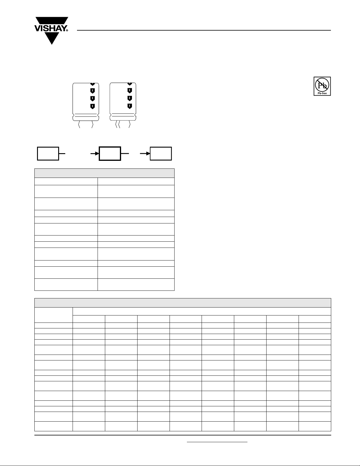
Fig.1 Component outlines
158
PUL-SI
miniaturized
QUICK REFERENCE DATA
DESCRIPTION VALUE
Nominal case sizes
(Ø D x L in mm)
Rated capacitance range
(E6/E12 series), C
Tolerance on C
Rated voltage range, U
Category temperature
range
Endurance test at 105 °C 2000 hours
Useful life at 105 °C 5000 hours
Useful life at 40 °C,
1.9 x I
applied
R
Shelf life at 0 V, 105 °C 500 hours
Based on sectional
specification
Climatic category
IEC 60068
R
R
R
090
PUL-SI
IEC 60384-4/EN130300
85 °C
22 x 25
to 35 x 40
560 µF to 47 000 µF
± 20 %
25 V to 100 V
- 40 °C to + 105 °C
125 000 hours
40/105/56
156
PUM-SI
090 PUL-SI
Vishay BCcomponents
FEATURES
• Polarized aluminum electrolytic capacitors,
non-solid electrolyte
• Large types, very small dimensions, cylindrical
aluminum case, insulated with a blue sleeve
• Low ESR, high ripple current capability
• Long useful life: up to 5000 hours at 105 °C
• Keyed polarity version available
APPLICATIONS
• General purpose, industrial, telecom and audio/video
systems
• Smoothing and filtering
• Standard and switched mode power supplies
• Energy storage in pulse systems
MARKING
The capacitors are marked (where possible) with the
following information:
• Rated capacitance (in µF)
• Tolerance on rated capacitance, code letter in accordance
with IEC 60062 (M for ± 20 %)
• Rated voltage (in V)
• Date code (YYMM)
• Name of manufacturer
• Code for factory of origin
• ‘-’ sign to identify the negative terminal, visible from the top
and side of the capacitor
• Code number
• Climatic category in accordance with IEC 60068
RoHS
COMPLIANT
SELECTION CHART FOR CR, UR AND RELEVANT NOMINAL CASE SIZES (Ø D x L in mm)
U
C
R
(µF)
560 -------22 x 25
680 ------22 x 2522 x 30
1000 ------22 x 3025 x 30
1200 ------25 x 30-
1500 -----22 x 25-
1800 -------30 x 35
2200 - - - - 22 x 25 22 x 30
2700 - - - - - 25 x 30 30 x 35 3300 - - - 22 x 25 22 x 30 25 x 40 30 x 40 35 x 40
3900 - - - 22 x 30 25 x 30
4700 - 22 x 25 22 x 30 22 x 30
5600 - - - 25 x 30 25 x 40 30 x 35 - 6800 22 x 25 22 x 30 25 x 30 25 x 40 30 x 30 30 x 40 - -
8200 - 25 x 30 -
10 000 22 x 30 25 x 40
Document Number: 28387 For technical questions, contact: aluminumcaps2@vishay.com
Revision: 18-Aug-08 1
16 25 35 40 50 63 80 100
25 x 40
30 x 30
30 x 30
30 x 35
30 x 40
(V)
R
25 x 40
30 x 30
25 x 40
30 x 30
25 x 40
25 x 30
25 x 40
30 x 35 35 x 40 - -
30 x 40 - - -
30 x 30
30 x 30
30 x 35
- -
35 x 40 -
30 x 40
www.vishay.com
Page 3
090 PUL-SI
y
Vishay BCcomponents
Aluminum Capacitors
Power Ultra Long Life Snap-In
SELECTION CHART FOR CR, UR AND RELEVANT NOMINAL CASE SIZES (Ø D x L in mm)
U
C
R
(µF)
12 000 -
15 000 25 x 30
16 25 35 40 50 63 80 100
25 x 40
30 x 30
30 x 35
30 x 40
- - - - - -
30 x 40 35 x 40 - - - -
18 000 - - - 35 x 40 - - - -
22 000
25 x 40
30 x 30
35 x 40 35 x 40 - - - - -
27 00030 x 35 - - - - - - 33 00030 x 40 - - - - - - 39 000 - - - - - - - -
47 000
30 x 40
35 x 40
- - - - - - -
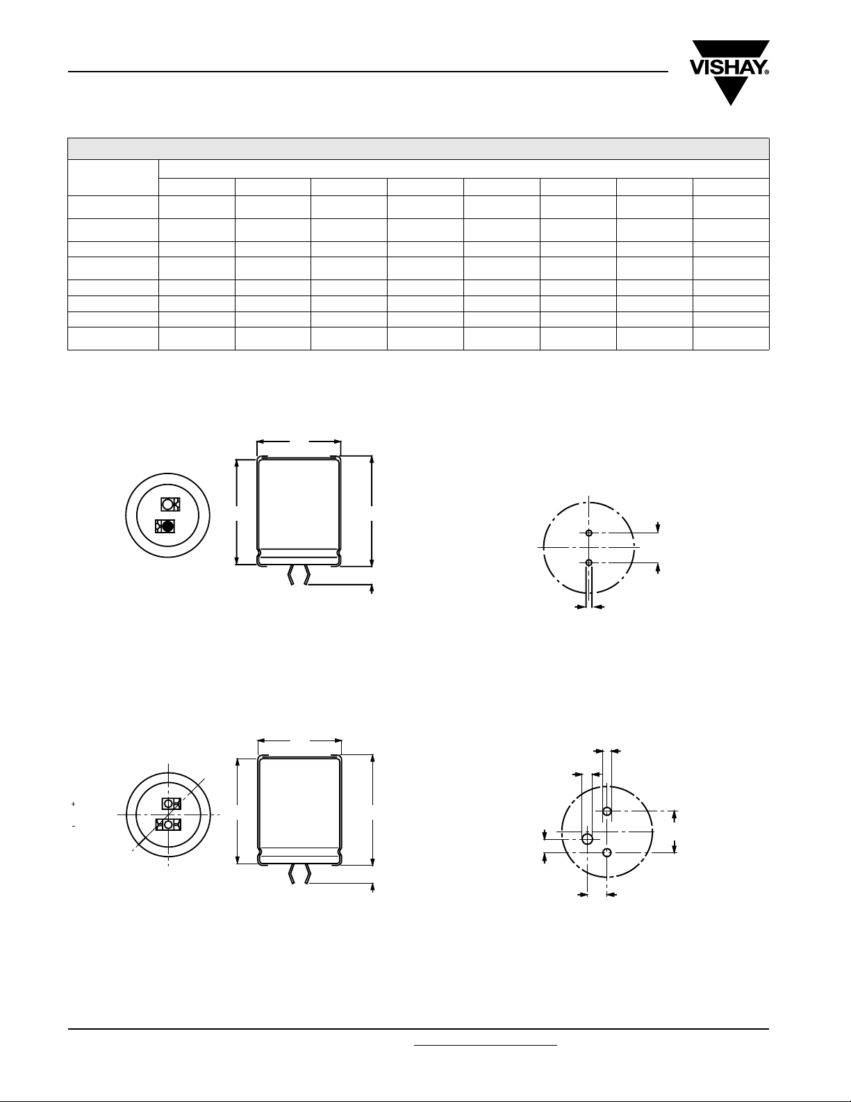
DIMENSIONS in millimeters AND AVAILABLE FORMS
TWO TERMINAL SNAP-IN
Ø D
R
(V)
+ TERMINAL
- TERMINAL
Bottom view
L
L + 2 max.
+ 0
5.8 mm
- 1
The minus terminal can be marked with a black dot or with an
imprinted ‘-’ sign.
Fig.2 Two terminal snap-in Fig.3 Mounting hole diagram
THREE TERMINAL SNAP-IN
Ø D
TERMINAL
TERMINAL
minus pole
marking
Bottom view
L
The negative terminal has TWO pins which are BOTH electricall
connected.
Fig.4 Three terminal snap-in
L + 2 max.
4 ± 0.5
10
± 0.1
Ø 2 ± 0.1 (2 x)
Ø 2 ± 0.1
(2 x)
Ø 2.5
± 0.1
10
3.3
± 0.1
4.75 ± 0.1
± 0.1
The 10 mm spacing of the 2 pin snap-in is used as the base layout
and a third hole is added.
The third hole is closer to the negative primary hole so that
polarization is always maintained, together with added mechanical
stability.
Fig.5 Mounting hole diagram
www.vishay.com For technical questions, contact: aluminumcaps2@vishay.com
Document Number: 28387
2 Revision: 18-Aug-08
Page 4

090 PUL-SI
Aluminum Capacitors
Vishay BCcomponents
Power Ultra Long Life Snap-In
Tab l e 1
DIMENSIONS in millimeters, MASS AND PACKAGING QUANTITIES
NOMINAL
CASE SIZE
Ø D x L
22 x 25 23 27 12 100 260 x 250 x 39
22 x 30 23 32 16 100 260 x 250 x 44
25 x 30 26 32 22 100 290 x 280 x 44
25 x 40 26 42 27 100 290 x 280 x 54
30 x 30 31 32 30 100 340 x 330 x 44
30 x 35 31 37 35 100 340 x 330 x 49
30 x 40 31 42 40 100 340 x 330 x 54
35 x 40 36 42 55 50 390 x 198 x 54
Ø D
max.
L
max.
ELECTRICAL DATA
SYMBOL DESCRIPTION
C
R
I
R
I
L5
ESR
Z max. impedance at 10 kHz
Notes
(1)
ESR at 120 Hz is approximately 0.95 x ESR 100 Hz
• Unless otherwise specified, all electrical values in Table 2 apply
at T
rated capacitance at 100 Hz
rated RMS ripple current at 100 Hz or 10 kHz,
105 °C
max. leakage current after 5 minutes at U
max. equivalent series resistance at 100 Hz
= 20 °C, P = 86 to 106 kPa, RH = 45 to 75 %
amb
MASS
(g)
PACKAGING QUANTITIES
(units per box)
ORDERING EXAMPLE
Electrolytic capacitor 090 series
3300 µF/80 V; ± 20 %
Nominal case size: Ø 30 x 40 mm
2-terminal snap-in:
R
(1)
Ordering code: MAL2090 32332E3
Former 12NC: 2222090 32332
3-terminal snap-in:
Ordering code: MAL2090 72332E3
Former 12NC: 2222090 72332
CARDBOARD BOX DIMENSIONS
L x W x H
(mm)
Tab l e 2
ELECTRICAL DATA AND ORDERING INFORMATION FOR 2 AND 3 TERMINAL SNAP-IN VERSIONS
C
U
R
(V)
16
25
35
Document Number: 28387 For technical questions, contact: aluminumcaps2@vishay.com
Revision: 18-Aug-08 3
R
100 Hz
(µF)
6800 22 x 25 2.8 3.3 222 82 66 15682E3 55682E3
10 000 22 x 30 3.4 4.0 324 59 48 15103E3 55103E3
15 000 25 x 30 3.6 4.3 484 53 44 25153E3 65153E3
22 000 25 x 40 4.5 5.5 708 38 33 25223E3 65223E3
22 000 30 x 30 3.7 4.5 708 54 43 35223E3 75223E3
27 000 30 x 35 4.2 5.1 868 45 36 35273E3 75273E3
33 000 30 x 40 4.7 5.6 1060 39 32 35333E3 75333E3
47 000 35 x 40 4.8 5.8 1508 43 32 45473E3 85473E3
4700 22 x 25 2.6 3.1 236 89 66 16472E3 56472E3
6800 22 x 30 3.2 3.8 341 65 49 16682E3 56682E3
8200 25 x 30 3.4 4.1 411 60 46 26822E3 66822E3
10 000 25 x 40 4.3 5.1 501 46 35 26103E3 66103E3
12 000 25 x 40 4.3 5.2 601 43 34 26123E3 66123E3
12 000 30 x 30 3.7 4.5 601 56 44 36123E3 76123E3
15 000 30 x 35 4.2 5.1 751 46 36 16153E3 56153E3
15 000 30 x 40 4.8 5.7 751 40 33 36153E3 76153E3
22 000 35 x 40 5.1 6.1 1101 40 31 46223E3 86223E3
4700 22 x 30 2.8 3.4 330 78 53 10472E3 50472E3
6800 25 x 30 3.0 3.6 477 70 50 20682E3 60682E3
10 000 25 x 40 3.9 4.7 701 49 36 20103E3 60103E3
10 000 30 x 30 3.2 3.9 701 70 49 30103E3 70103E3
15 000 30 x 40 4.1 4.9 1051 49 35 30153E3 70153E3
22 000 35 x 40 4.2 5.0 1541 55 35 40223E3 80223E3
NOMINAL
CASE SIZE
Ø D x L
(mm)
I
R
100 Hz
105 °C
(A)
I
R
10 kHz
105 °C
(A)
I
L5
5min
(mA)
MAX. ESR
100 Hz
(mΩ)
(1)
MAX. Z
10 kHz
(mΩ)
ORDERING CODE
MAL2090.......
2-TERM. SI 3-TERM. SI
www.vishay.com
Page 5

090 PUL-SI
Vishay BCcomponents
Aluminum Capacitors
Power Ultra Long Life Snap-In
ELECTRICAL DATA AND ORDERING INFORMATION FOR 2 AND 3 TERMINAL SNAP-IN VERSIONS
U
(V)
40
50
63
80
100
C
R
R
100 Hz
(µF)
3300 22 x 25 2.4 2.9 265 99 70 17332E3 57332E3
3900 22 x 30 2.9 3.4 313 76 54 17392E3 57392E3
4700 22 x 30 2.9 3.5 377 71 51 17472E3 57472E3
5600 25 x 30 3.1 3.7 449 69 50 27562E3 67562E3
6800 25 x 40 3.9 4.7 545 51 38 27682E3 67682E3
8200 30 x 30 3.3 3.9 657 69 49 37822E3 77822E3
10 000 30 x 35 3.8 4.5 801 56 41 17103E3 57103E3
10 000 30 x 40 4.3 5.1 801 48 36 37103E3 77103E3
15 000 35 x 40 4.5 5.4 1201 50 35 47153E3 87153E3
18 000 35 x 40 4.3 5.1 1441 54 35 47183E3 87183E3
2200 22 x 25 2.1 2.6 221 145 106 11222E3 51222E3
3300 22 x 30 2.6 3.2 331 101 76 11332E3 51332E3
3900 25 x 30 2.8 3.4 391 93 71 21392E3 61392E3
4700 25 x 30 2.9 3.5 471 85 70 31472E3 71472E3
4700 25 x 40 3.6 4.3 471 71 55 21472E3 61472E3
5600 25 x 40 3.6 4.4 561 66 51 21562E3 61562E3
6800 30 x 30 3.1 3.7 681 83 65 31682E3 71682E3
8200 30 x 35 3.5 4.2 821 68 54 31822E3 71822E3
10 000 30 x 40 4.0 4.7 1001 58 46 31103E3 71103E3
15 000 35 x 40 4.0 4.9 1501 63 45 41153E3 81153E3
1500 22 x 25 2.1 2.5 190 161 126 18152E3 58152E3
2200 22 x 30 2.6 3.1 279 114 90 18222E3 58222E3
2700 25 x 30 2.8 3.4 342 101 81 28272E3 68272E3
3300 25 x 40 3.5 4.2 417 79 63 28332E3 68332E3
3900 25 x 40 3.6 4.3 493 71 58 28392E3 68392E3
3900 30 x 30 3.1 3.8 493 89 74 38392E3 78392E3
4700 30 x 30 3.1 3.7 594 88 71 18472E3 58472E3
4700 30 x 35 3.6 4.3 594 74 61 38472E3 78472E3
5600 30 x 35 3.5 4.2 707 71 59 38562E3 78562E3
6800 30 x 40 4.0 4.7 858 61 51 38682E3 78682E3
8200 35 x 40 4.3 5.1 1035 61 50 48822E3 88822E3
820 22 x 25 1.5 1.8 133 244 184 12821E3 52821E3
1000 22 x 30 1.8 2.1 161 196 146 12102E3 52102E3
1500 25 x 30 2.1 2.6 241 145 113 22152E3 62152E3
2200 25 x 40 2.8 3.3 353 101 79 22222E3 62222E3
2200 30 x 30 2.5 3.0 353 119 96 32222E3 72222E3
2700 30 x 35 2.8 3.4 433 98 79 32272E3 72272E3
3300 30 x 40 3.2 3.8 529 81 66 32332E3 72332E3
4700 35 x 40 3.4 4.1 753 75 63 42472E3 82472E3
560 22 x 25 1.4 1.6 113 269 184 19561E3 59561E3
680 22 x 30 1.6 1.9 137 216 146 19681E3 59681E3
1000 25 x 30 1.9 2.3 201 163 114 29102E3 69102E3
1500 25 x 40 2.5 3.1 301 111 79 29152E3 69152E3
1500 30 x 30 2.3 2.7 301 130 98 39152E3 79152E3
1800 30 x 35 2.6 3.2 361 108 80 39182E3 79182E3
2200 30 x 40 3.0 3.6 441 90 68 39222E3 79222E3
3300 35 x 40 3.2 3.8 661 81 64 49332E3 89332E3
NOMINAL
CASE SIZE
Ø D x L
(mm)
I
R
100 Hz
105 °C
(A)
I
R
10 kHz
105 °C
(A)
I
L5
5min
(mA)
MAX. ESR
100 Hz
(mΩ)
(1)
MAX. Z
10 kHz
(mΩ)
ORDERING CODE
MAL2090.......
2-TERM. SI 3-TERM. SI
www.vishay.com For technical questions, contact: aluminumcaps2@vishay.com
4 Revision: 18-Aug-08
Document Number: 28387
Page 6

090 PUL-SI
Aluminum Capacitors
Power Ultra Long Life Snap-In
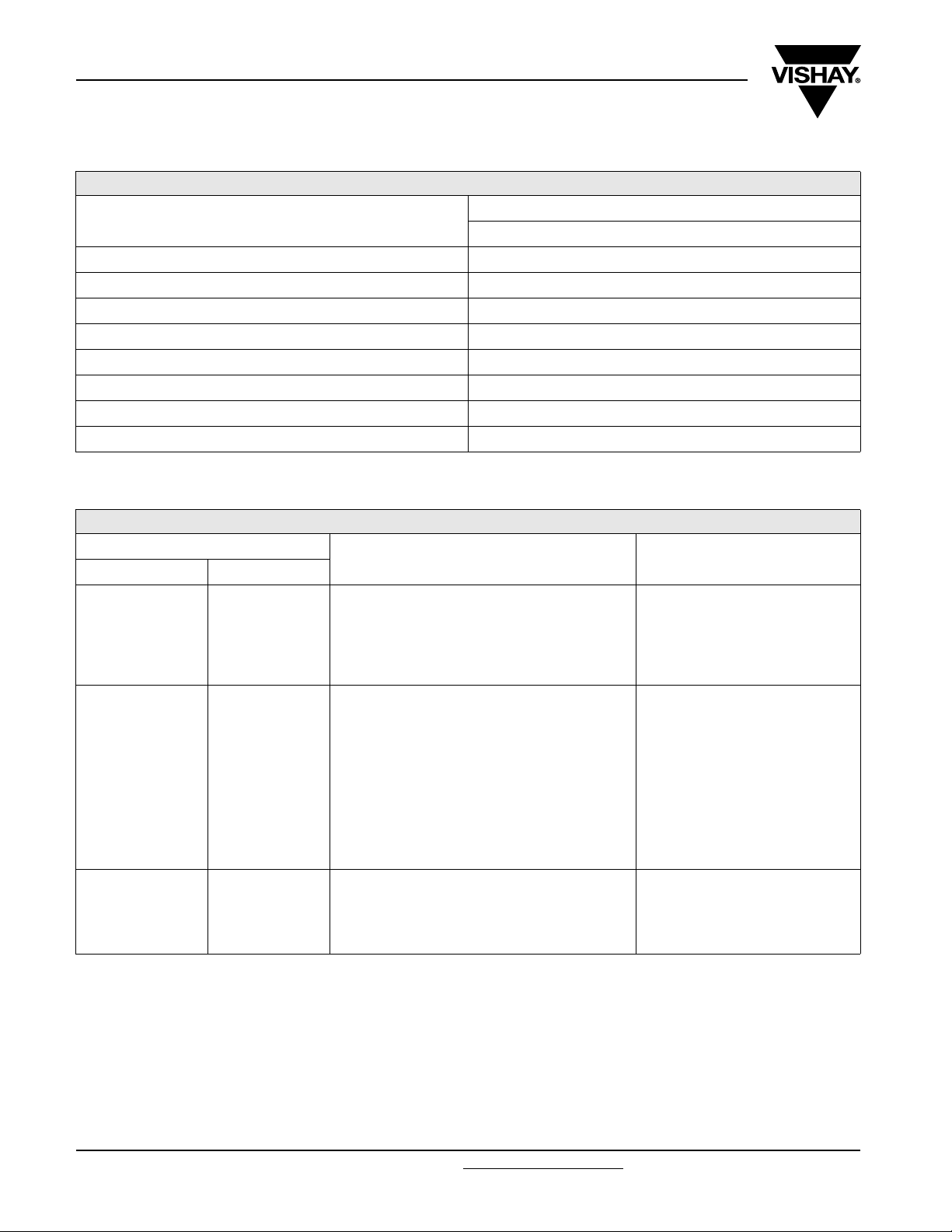
ADDITIONAL ELECTRICAL DATA
PARAMETER CONDITIONS VALUE
Voltage
Surge voltage U
Reverse voltage U
Current
Leakage current
After 1 minute at U
After 5 minutes at U
Inductance
Equivalent series inductance (ESL) All case sizes
RIPPLE CURRENT AND USEFUL LIFE
I
I
A
R
R
R
2.7
2.6
Vishay BCcomponents
=1.15xU
s
≤ 1V
rev
IL1≤ 0.006 CRxUR + 4 µA
I
≤ 0.002 CRxUR + 4 µA
L5
typ. 19 nH
max. 25 nH
R
MGA 454
IA= actual ripple current at 100 Hz
I
= rated ripple current at 100 Hz and 105 °C
R
(1)
Useful life at 105 °C and IR applied: 5000 hours
2.5
2.4
2.3
2.2
2.1
2.0
1.9
1.8
1.7
1.6
1.5
1.4
1.3
1.2
1.1
400
1.0
600
0.8
0.5
0.0
40 50 60 70 80 90
300
200
150
100
60
40
30
20
15
10
3
4
5
7
2.5
1
1.2
1.5
2
life multiplier
(1 )
100 11 0
T
(°C)
amb
Fig.6 Multiplier of useful life as a function of ambient temperature and ripple current load
Document Number: 28387 For technical questions, contact: aluminumcaps2@vishay.com
www.vishay.com
Revision: 18-Aug-08 5
Page 7
090 PUL-SI
Vishay BCcomponents
Aluminum Capacitors
Power Ultra Long Life Snap-In
Tab l e 3
MULTIPLIER OF RIPPLE CURRENT (IR) AS A FUNCTION OF FREQUENCY
MULTIPLIER
I
FREQUENCY
(HZ)
50 0.91
100 1.00
200 1.05
400 1.09
1000 1.13
2000 1.15
4000 1.18
≥ 10 000 1.22
Tab l e 4
TEST PROCEDURES AND REQUIREMENTS
TEST
NAME OF TEST REFERENCE
Endurance IEC 60384-4/
EN130300
subclause 4.13
Useful life CECC 30301
subclause 1.8.1
Shelf life
(storage at
high temperature)
IEC 60384-4/
EN130300
subclause 4.17
T
= 105 °C; UR applied;
amb
2000 hours
= 105 °C; UR and IR applied;
T
amb
5000 hours
= 105 °C; no voltage applied;
T
amb
500 hours
after test: U
24 hours to 48 hours before measurement
R
PROCEDURE
(QUICK REFERENCE)
to be applied for 30 minutes,
R
= 25 to 100 V
U
R
ΔC/C: ± 15 %
ESR ≤ 1.3 x spec. limit
Z ≤ 2xspec. limit
I
L5
ΔC/C: ± 20 %
ESR ≤ 3 x spec. limit
Z ≤ 3xspec. limit
I
L5
no short or open circuit,
no visible damage
total failure percentage:
U
R
ΔC/C: ± 15 %
ESR ≤ 1.5 x spec. limit
I
L5
REQUIREMENTS
≤ spec. limit
≤ spec. limit
: ≤ 1 %
≤ 2 x spec. limit
www.vishay.com For technical questions, contact: aluminumcaps2@vishay.com
6 Revision: 18-Aug-08
Document Number: 28387
Page 8

Legal Disclaimer Notice
Vishay
Disclaimer
All product specifications and data are subject to change without notice.
Vishay Intertechnology, Inc., its affiliates, agents, and employees, and all persons acting on its or their behalf
(collectively, “Vishay”), disclaim any and all liability for any errors, inaccuracies or incompleteness contained herein
or in any other disclosure relating to any product.
Vishay disclaims any and all liability arising out of the use or application of any product described herein or of any
information provided herein to the maximum extent permitted by law. The product specifications do not expand or
otherwise modify Vishay’s terms and conditions of purchase, including but not limited to the warranty expressed
therein, which apply to these products.
No license, express or implied, by estoppel or otherwise, to any intellectual property rights is granted by this
document or by any conduct of Vishay.
The products shown herein are not designed for use in medical, life-saving, or life-sustaining applications unless
otherwise expressly indicated. Customers using or selling Vishay products not expressly indicated for use in such
applications do so entirely at their own risk and agree to fully indemnify Vishay for any damages arising or resulting
from such use or sale. Please contact authorized Vishay personnel to obtain written terms and conditions regarding
products designed for such applications.
Product names and markings noted herein may be trademarks of their respective owners.
Document Number: 91000 www.vishay.com
Revision: 18-Jul-08 1
 Loading...