

Page 1

6121 Baker Road,
Suite 108
Minnetonka, MN 55345
www.chtechnology.com
Phone (952) 933-6190
Fax (952) 933-6223
1-800-274-4284
Thank you for downloading this document from C&H Technology, Inc.
Please contact the C&H Technology team for the following questions -
Technical
Application
Assembly
Availability
Pricing
Phone – 1-800-274-4284
E-Mail – sales@chtechnology.com
www.chtechnology.com - SPECIALISTS IN POWER ELECTRONIC COMPONENTS AND ASSEMBLIES - www.chtechnology.com
Page 2
Aluminum Capacitors
Power Standard Miniature Snap-In
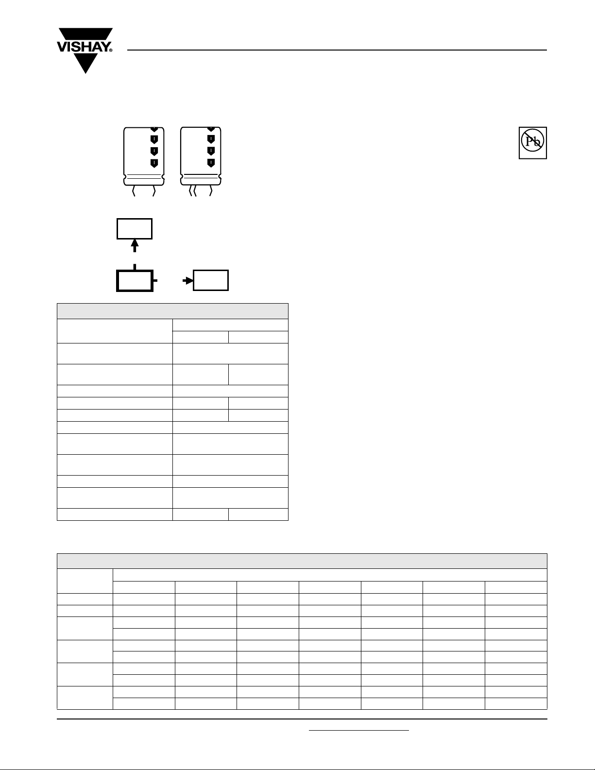
Fig. 1 Component outlines
156/157
PUM-SI
smaller
dimensions
056/057
PSM-SI
long life
105 °C
QUICK REFERENCE DATA
DESCRIPTION
Nominal case size
(Ø D x L in mm)
Rated capacitance range
(E6 series), C
Tolerance on C
Rated voltage range, U
Category temperature range - 40 to + 85 °C - 25 to + 85 °C
Endurance test at 85 °C 5000 hours (450 V: 2000 hours)
Useful life at 85 °C
Useful life at 40 °C and
1.4 x I
Shelf life at 0 V, 85 °C 500 hours
Based on sectional
specification
Climatic category IEC 60068 40/085/056 25/085/56
Note
(1)
A 420 V range is available on request
applied
R
R
R
(1)
R
058/059
PLL-SI
VAL UE
056 057
22 x 25 to 35 x 50
470 to
68 000 µF
± 20 %
10 to 100 V 200 to 450 V
12 000 hours
(450 V: 5000 hours)
210 000 hours
(450 V: 90 000 hours)
IEC 60384-4/EN130300
47 to
1500 µF
056/057 PSM-SI
Vishay BCcomponents
FEATURES
• Polarized aluminum electrolytic capacitors,
non-solid electrolyte
• Large types, minimized dimensions, cylindrical
aluminum case, insulated with a blue sleeve
• Pressure relief on the top of the aluminum case
• Charge and discharge proof
• Long useful life: 12 000 hours at 85 °C
• High ripple current capability
• Keyed polarity version available
APPLICATIONS
• General purpose, industrial and audio/video systems
• Smoothing and filtering
• Standard and switched mode power supplies
• Energy storage in pulse systems
MARKING
The capacitors are marked (where possible) with the
following information:
• Rated capacitance (in µF)
• Tolerance code on rated capacitance, code letter in
accordance with IEC 60062 (M for ± 20 %)
• Rated voltage (in V)
• Date code (YYMM)
• Name of manufacturer
• Code for factory of origin
• ‘−’ sign to identify the negative terminal, visible from the top
and side of the capacitor
• Code number
• Climatic category in accordance with IEC 60068
Pb-free
Available
RoHS
COMPLIANT
SELECTION CHART FOR CR, UR AND RELEVANT NOMINAL CASE SIZES FOR 056 SERIES
U
C
R
(µF)
470 ------22 x 25
680 ------22 x 30
1000
1500
2200
3300
Document Number: 28340 For technical questions, contact: aluminumcaps2@vishay.com
Revision: 18-Aug-08 1
10 16 25 40 50 63 100
-----22 x 2525 x 30
------22 x 40
----22 x 2522 x 3030 x 30
------25 x 40
- - - 22 x 25 22 x 30 25 x 30 30 x 40
-----22 x 4025 x 50
- - 22 x 25 22 x 30 25 x 30 30 x 30 35 x 40
----22 x 4025 x 4030 x 50
R
(V)
(Ø D x L in mm)
www.vishay.com
Page 3
056/057 PSM-SI
Vishay BCcomponents
Aluminum Capacitors
Power Standard Miniature Snap-In
SELECTION CHART FOR CR, UR AND RELEVANT NOMINAL CASE SIZES FOR 056 SERIES
U
C
R
(µF)
4700
6800
10 000
15 000
22 000
33 000
47 000
68 00035 x 50------
10 16 25 40 50 63 100
- 22 x 25 22 x 30 25 x 30 30 x 30 30 x 40 35 x 50
- - - 22 x 40 25 x 40 25 x 50 -
22 x 25 22 x 30 25 x 30 30 x 30 30 x 40 35 x 40 -
- - 22 x 40 25 x 40 25 x 50 30 x 50 -
22 x 30 25 x 30 30 x 30 30 x 40 35 x 40 35 x 50 -
- 22 x 40 25 x 40 25 x 50 30 x 50 - -
25 x 30 30 x 30 30 x 40 35 x 40 35 x 50 - -
22 x 40 25 x 40 25 x 50 30 x 50 - - -
30 x 30 30 x 40 35 x 40 35 x 50 - - -
25 x 4025 x 5030 x 50----
30 x 4035 x 4035 x 50----
25 x 5030 x 50-----
35 x 4035 x 50-----
30 x 50------
R
(V)
(Ø D x L in mm)
SELECTION CHART FOR CR, UR AND RELEVANT NOMINAL CASE SIZES FOR 057 SERIES
U
C
R
(µF)
47 - - 22 x 25 22 x 25 22 x 30
68 - - 22 x 30 22 x 30 22 x 30
100
150
220
330
470
680
1000
1500 35 x 50 - - - -
200 250 385 400 450
- 22 x 25 25 x 30 25 x 30 30 x 30
- - 22 x 40 22 x 35 25 x 35
- - 22 x 35 - -
22 x 25 22 x 30 30 x 30 30 x 30 25 x 50
- - 25 x 40 - 30 x 35
- - - 25 x 40 -
22 x 30 25 x 30 30 x 45 30 x 35 35 x 40
- 22 x 40 30 x 40 25 x 40 30 x 45
- - 30 x 35 - -
- - 25 x 50 - -
25 x 30 30 x 30 35 x 35 35 x 40 35 x 50
22 x 40 25 x 40 - 35 x 50 35 x 45
30 x 30 30 x 40 35 x 50 35 x 50 -
25 x 40 25 x 50 35 x 45 - -
30 x 40 35 x 40 - - -
25 x 50 30 x 50 - - -
35 x 40 35 x 50 - - -
30 x 50 - - - -
R
(V)
(Ø D x L in mm)
www.vishay.com For technical questions, contact: aluminumcaps2@vishay.com
2 Revision: 18-Aug-08
Document Number: 28340
Page 4
056/057 PSM-SI
Aluminum Capacitors
Vishay BCcomponents
Power Standard Miniature Snap-In
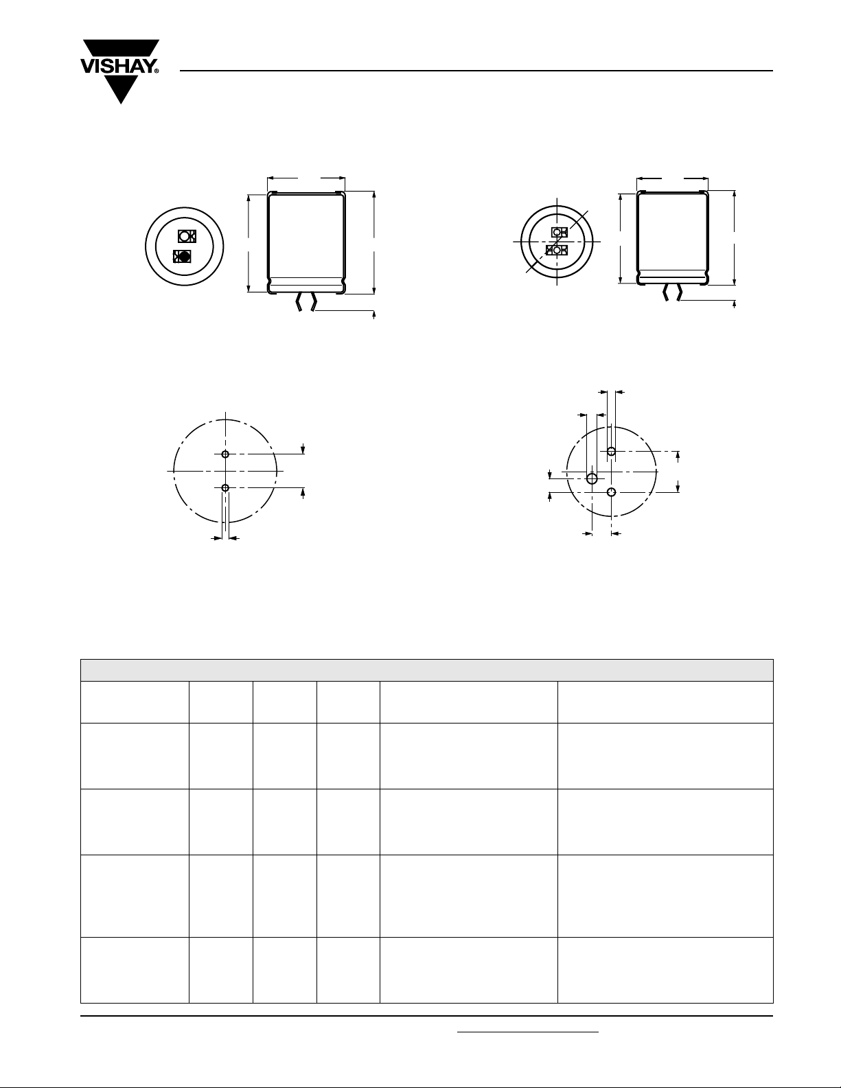
DIMENSIONS in millimeters AND AVAILABLE FORMS
TWO TERMINALS SNAP-IN THREE TERMINAL SNAP-IN
+ TERMINAL
- TERMINAL
Bottom view
The minus terminal can be marked with a black dot or with an
imprinted ‘-’ sign.
Fig.2 Two terminal snap-in
Ø D
10 ± 0.1
L + 2 max.L
+ 0
5.8 mm
- 1
+ TERMINAL
- TERMINAL
minus pole
marking
Bottom view
L
The negative terminal has TWO pins which are BOTH
electrically connected.
Fig.4 Three terminal snap-in
Ø 2 ± 0.1 (2 x)
Ø 2.5 ± 0.1
3.3 ± 0.1
Ø D
L ± 2 max.
4 ± 0.5
10 ± 0.1
Ø 2 ± 0.1 (2 x)
4.75 ± 0.1
The 10 mm spacing of the 2 pin snap-in is used as the base
layout and a third hole is added.
The third hole is closer to the negative primary hole so that
polarization is always maintained, together with added
mechanical stability.
Fig.3 Mounting hole diagram
Tab l e 1
Fig.5 Mounting hole diagram
DIMENSIONS in millimeters, MASS AND PACKAGING QUANTITIES
NOMINAL
CASE SIZE
Ø D x L
22 x 25 23 27 ≈ 12 100 260 x 250 x 39
22 x 30 23 32 ≈ 16 100 260 x 250 x 44
22 x 35 23 37 ≈ 20 100 260 x 250 x 49
22 x 40 23 42 ≈ 23 100 260 x 250 x 54
25 x 30 26 32 ≈ 22 100 290 x 280 x 44
25 x 35 26 37 ≈ 24 100 290 x 280 x 49
25 x 40 26 42 ≈ 27 100 290 x 280 x 54
25 x 50 26 52 ≈ 38 100 290 x 280 x 64
30 x 30 31 32 ≈ 30 100 340 x 330 x 44
30 x 35 31 37 ≈ 35 100 340 x 330 x 49
30 x 40 31 42 ≈ 40 100 340 x 330 x 54
30 x 45 31 47 ≈ 45 100 340 x 330 x 59
30 x 50 31 52 ≈ 50 100 340 x 330 x 64
35 x 35 36 37 ≈ 48 50 390 x 198 x 49
35 x 40 36 42 ≈ 55 50 390 x 198 x 54
35 x 45 36 47 ≈ 63 50 390 x 198 x 59
35 x 50 36 52 ≈ 72 50 390 x 198 x 64
Document Number: 28340 For technical questions, contact: aluminumcaps2@vishay.com
Revision: 18-Aug-08 3
Ø D
max.
L
max.
MASS
(g)
PACKAGING QUANTITIES
(units per box)
CARDBOARD BOX DIMENSIONS
L x W x H
(mm)
www.vishay.com
Page 5

056/057 PSM-SI
Vishay BCcomponents
Aluminum Capacitors
Power Standard Miniature Snap-In
ELECTRICAL DATA
SYMBOL DESCRIPTION
C
R
I
R
I
L1
I
L5
ESR max. equivalent series resistance at 100 Hz
Z max. impedance at 10 kHz
Note
• Unless otherwise specified, all electrical values in Tables 2 and 3
apply at T
Tab l e 2
rated capacitance at 100 Hz
rated RMS ripple current at 100 Hz
or ≥ 10 kHz and 85 °C
max. leakage current after 1 minute at U
max. leakage current after 5 minutes at U
= 20 °C, P = 86 to 106 kPa, RH = 45 to 75 %
amb
R
R
ELECTRICAL DATA AND ORDERING INFORMATION FOR 056 SERIES
C
U
R
(V)
10
16
25
www.vishay.com For technical questions, contact: aluminumcaps2@vishay.com
4 Revision: 18-Aug-08
R
100 Hz
(µF)
6800 22 x 25 2.04 2.40 412 140 76 62 54682E3 74682E3
10 000 22 x 30 2.56 3.02 608 205 56 45 54103E3 74103E3
15 000 25 x 30 3.12 3.68 904 304 44 39 54153E3 74153E3
15 000 22 x 40 3.39 4.00 904 304 41 34 44153E3 24153E3
22 000 30 x 30 3.47 4.09 1324 444 44 37 54223E3 74223E3
22 000 25 x 40 4.12 4.86 1324 444 34 28 44223E3 24223E3
33 000 30 x 40 4.58 5.40 1984 664 32 28 54333E3 74333E3
33 000 25 x 50 4.70 5.55 1984 664 30 27 44333E3 24333E3
47 000 35 x 40 5.10 6.02 2824 944 31 26 54473E3 74473E3
47 000 30 x 50 5.39 6.36 2824 944 28 24 44473E3 24473E3
68 000 35 x 50 5.88 6.94 4084 1364 28 23 54683E3 74683E3
4700 22 x 25 2.01 2.37 455 154 79 62 55472E3 75472E3
6800 22 x 30 2.54 3.00 657 222 57 45 55682E3 75682E3
10 000 25 x 30 3.02 3.56 964 324 47 39 55103E3 75103E3
10 000 22 x 40 3.28 3.87 964 324 44 34 45103E3 25103E3
15 000 30 x 30 3.36 3.96 1444 484 47 37 55153E3 75153E3
15 000 25 x 40 4.00 4.72 1444 484 34 28 45153E3 25153E3
22 000 30 x 40 4.51 5.32 2116 708 33 28 55223E3 75223E3
22 000 25 x 50 3.97 4.68 2116 708 42 41 45223E3 25223E3
33 000 35 x 40 5.02 5.92 3172 1060 32 28 55333E3 75333E3
33 000 30 x 50 4.75 5.61 3172 1060 36 34 45333E3 25333E3
47 000 35 x 50 5.34 6.30 4516 1508 34 32 55473E3 75473E3
3300 22 x 25 1.88 2.22 499 169 89 61 56332E3 76332E3
4700 22 x 30 2.37 2.80 709 239 65 45 56472E3 76472E3
6800 25 x 30 2.81 3.32 1024 344 54 41 56682E3 76682E3
6800 22 x 40 3.16 3.73 1024 344 47 38 46682E3 26682E3
10 000 30 x 30 3.25 3.84 1504 504 50 38 56103E3 76103E3
10 000 25 x 40 3.73 4.40 1504 504 39 30 46103E3 26103E3
15 000 30 x 40 4.73 5.58 2254 754 30 28 56153E3 76153E3
15 000 25 x 50 3.92 4.63 2254 754 43 39 46153E3 26153E3
22 000 35 x 40 4.48 5.29 3304 1104 40 28 56223E3 76223E3
22 000 30 x 50 4.96 5.85 3304 1104 36 23 46223E3 26223E3
33 000 35 x 50 4.98 5.88 4954 1654 39 33 56333E3 76333E3
NOMINAL
CASE SIZE
Ø D x L
(mm)
I
R
100 Hz
85 °C
(A)
I
R
≥ 10 kHz
85 °C
(A)
1 min
(µA)
ORDERING EXAMPLE
Electrolytic capacitor 056 series
10 000 µF/25 V; ± 20 %
Nominal case size: Ø 25 x 40 mm
2-terminal snap-in
Ordering code: MAL2056 46103E3
Former 12NC: 2222056 46103
3-terminal snap-in
Ordering code: MAL2056 26103E3
Former 12NC: 2222056 26103
I
L1
I
L5
5 min
(µA)
ESR
100 Hz
(mΩ)
Z
10 kHz
(mΩ)
ORDERING CODE
MAL2056.......
2-TERM. 3-TERM.
Document Number: 28340
Page 6

056/057 PSM-SI
Aluminum Capacitors
Vishay BCcomponents
Power Standard Miniature Snap-In
ELECTRICAL DATA AND ORDERING INFORMATION FOR 056 SERIES
U
(V)
40
50
63
100
C
R
R
100 Hz
(µF)
2200 22 x 25 1.85 2.26 532 180 92 61 57222E3 77222E3
3300 22 x 30 2.09 2.55 796 260 67 45 57332E3 77332E3
4700 25 x 30 2.28 2.78 1132 380 82 70 57472E3 77472E3
4700 22 x 40 3.10 3.78 1132 380 49 38 47472E3 27472E3
6800 30 x 30 3.16 3.85 1636 548 53 38 57682E3 77682E3
6800 25 x 40 3.06 3.73 1636 548 58 50 47682E3 27682E3
10 000 30 x 40 4.20 5.12 2404 804 38 28 57103E3 77103E3
10 000 25 x 50 3.88 4.73 2404 804 44 39 47103E3 27103E3
15 000 35 x 40 4.05 4.94 3604 1204 49 41 57153E3 77153E3
15 000 30 x 50 4.45 5.43 3604 1204 41 34 47153E3 27153E3
22 000 35 x 50 4.86 5.93 5284 1764 40 33 57223E3 77223E3
1500 22 x 25 1.36 1.66 454 154 170 130 51152E3 71152E3
2200 22 x 30 1.75 2.14 664 224 120 91 51222E3 71222E3
3300 25 x 30 2.17 2.65 994 334 90 72 51332E3 71332E3
3300 22 x 40 2.42 2.95 994 334 80 63 41332E3 21332E3
4700 30 x 30 2.65 3.23 1414 474 75 63 51472E3 71472E3
4700 25 x 40 2.89 3.53 1414 474 65 52 41472E3 21472E3
6800 30 x 40 3.56 4.34 2044 684 53 45 51682E3 71682E3
6800 25 x 50 3.75 4.58 2044 684 50 43 41682E3 21682E3
10 000 35 x 40 4.05 4.94 3004 1004 49 42 51103E3 71103E3
10 000 30 x 50 4.50 5.49 3004 1004 40 35 41103E3 21103E3
15 000 35 x 50 4.98 6.08 4504 1504 39 33 51153E3 71153E3
1000 22 x 25 1.46 1.78 382 130 148 104 58102E3 78102E3
1500 22 x 30 1.87 2.28 571 193 105 72 58152E3 78152E3
2200 25 x 30 2.32 2.83 836 281 79 59 58222E3 78222E3
2200 22 x 40 2.54 3.10 836 281 73 53 48222E3 28222E3
3300 30 x 30 2.87 3.50 1251 420 64 50 58332E3 78332E3
3300 25 x 40 3.14 3.83 1251 420 55 44 48332E3 28332E3
4700 30 x 40 3.67 4.48 1780 596 50 38 58472E3 78472E3
4700 25 x 50 3.71 4.53 1780 596 48 38 48472E3 28472E3
6800 35 x 40 4.33 5.28 2574 861 43 38 58682E3 78682E3
6800 30 x 50 4.75 5.80 2574 861 42 37 48682E3 28682E3
10 000 35 x 50 5.26 6.42 3784 1264 35 30 58103E3 78103E3
470 22 x 25 0.77 0.94 286 98 535 470 59471E3 79471E3
680 22 x 30 0.99 1.21 412 160 375 328 59681E3 79681E3
1000 25 x 30 1.27 1.55 604 204 265 235 59102E3 79102E3
1000 22 x 40 1.35 1.65 604 204 260 225 49102E3 29102E3
1500 30 x 30 1.67 2.04 904 304 190 170 59152E3 79152E3
1500 25 x 40 1.75 2.14 904 304 180 160 49152E3 29152E3
2200 30 x 40 2.27 2.77 1324 444 130 120 59222E3 79222E3
2200 25 x 50 2.30 2.80 1324 444 125 110 49222E3 29222E3
3300 35 x 40 2.84 3.46 1984 664 100 95 59332E3 79332E3
3300 30 x 50 2.97 3.62 1984 664 92 85 49332E3 29332E3
4700 35 x 50 3.59 4.38 2824 677 75 70 59472E3 79472E3
NOMINAL
CASE SIZE
Ø D x L
(mm)
I
R
100 Hz
85 °C
(A)
I
R
≥ 10 kHz
85 °C
(A)
I
L1
1 min
(µA)
I
L5
5 min
(µA)
ESR
100 Hz
(mΩ)
10 kHz
Z
(mΩ)
ORDERING CODE
MAL2056.......
2-TERM. 3-TERM.
Document Number: 28340 For technical questions, contact: aluminumcaps2@vishay.com
Revision: 18-Aug-08 5
www.vishay.com
Page 7

056/057 PSM-SI
Vishay BCcomponents
Aluminum Capacitors
Power Standard Miniature Snap-In
Tab l e 3
ELECTRICAL DATA AND ORDERING INFORMATION FOR 057 SERIES
I
C
U
R
(V)
200
250
385
400
450
www.vishay.com For technical questions, contact: aluminumcaps2@vishay.com
6 Revision: 18-Aug-08
R
100 Hz
(µF)
150 22 x 25 0.77 184 64 950 620 52151E3 72151E3
220 22 x 30 1.00 268 92 650 435 52221E3 72221E3
330 25 x 30 1.36 400 136 430 310 52331E3 72331E3
330 22 x 40 1.36 400 136 430 310 42331E3 22331E3
470 30 x 30 1.80 568 192 310 230 52471E3 72471E3
470 25 x 40 1.80 568 192 310 230 42471E3 22471E3
680 30 x 40 2.39 820 276 210 180 52681E3 72681E3
680 25 x 50 2.39 820 276 210 180 42681E3 22681E3
1000 35 x 40 2.85 1204 404 160 135 52102E3 72102E3
1000 30 x 50 2.85 1204 404 160 135 42102E3 22102E3
1500 35 x 50 3.66 1804 604 120 105 52152E3 72152E3
100 22 x 25 0.63 154 54 1440 770 53101E3 73101E3
150 22 x 30 0.83 229 79 960 520 53151E3 73151E3
220 25 x 30 1.10 334 114 660 365 53221E3 73221E3
220 22 x 40 1.10 334 114 660 365 43221E3 23221E3
330 30 x 30 1.49 499 169 440 265 53331E3 73331E3
330 25 x 40 1.49 499 169 440 265 43331E3 23331E3
470 30 x 40 1.98 709 239 310 185 53471E3 73471E3
470 25 x 50 1.98 709 239 310 185 43471E3 23471E3
680 35 x 40 2.60 1024 344 240 145 53681E3 73681E3
680 30 x 50 2.60 1024 344 240 145 43681E3 23681E3
1000 35 x 50 3.12 1504 504 160 105 53102E3 73102E3
47 22 x 25 0.50 112 40 3000 1400 58479E3 78479E3
68 22 x 30 0.63 161 56 2100 1000 58689E3 68689E3
100 25 x 30 0.86 235 81 1400 780 58101E3 78101E3
100 22 x 40 0.86 235 81 1400 780 48101E3 68101E3
100 22 x 35 0.84 235 81 1400 780 38101E3 88101E3
150 30 x 30 1.16 350 119 950 520 58151E3 78151E3
150 25 x 40 1.16 350 119 950 520 48151E3 68151E3
220 30 x 40 1.57 512 173 650 400 58221E3 78221E3
220 30 x 35 1.50 512 173 650 400 38221E3 90051E3
220 25 x 50 1.57 512 173 650 400 48221E3 68221E3
330 35 x 35 1.73 766 258 480 280 68331E3 88331E3
330 30 x 45 1.75 766 258 480 280 38331E3 78331E3
470 35 x 50 2.40 1089 366 340 220 58471E3 78471E3
470 35 x 45 2.29 1089 366 340 220 48471E3 28471E3
47 22 x 25 0.50 117 42 3000 1400 56479E3 76479E3
68 22 x 30 0.63 167 58 2100 1000 56689E3 76689E3
100 25 x 30 0.86 244 84 1400 780 56101E3 76101E3
100 22 x 35 0.84 240 84 1400 780 36101E3 66101E3
150 30 x 30 1.16 364 124 950 520 56151E3 90054E3
150 25 x 40 1.16 364 124 950 520 46151E3 86151E3
220 30 x 35 1.50 532 180 650 400 36221E3 90055E3
220 25 x 50 1.57 532 180 650 400 46221E3 86221E3
330 35 x 40 1.85 796 268 480 280 56331E3 76331E3
330 30 x 50 1.85 796 268 480 280 46331E3 26331E3
470 35 x 50 2.40 1132 380 340 220 56471E3 76471E3
47 22 x 30 0.26 131 45 5600 4400 67479E3 87479E3
68 22 x 30 0.33 188 65 3900 3100 57689E3 77689E3
100 30 x 30 0.48 274 94 2600 2100 57101E3 77101E3
100 25 x 35 0.46 274 94 2600 2100 37101E3 17101E3
150 30 x 35 0.66 409 140 1600 1300 37151E3 17151E3
150 25 x 50 0.70 409 140 1600 1300 47151E3 27151E3
220 35 x 40 0.92 598 202 1100 900 57221E3 77221E3
220 30 x 45 0.73 598 202 1100 900 37221E3 17221E3
330 35 x 50 1.26 895 301 700 600 57331E3 77331E3
330 35 x 45 1.20 895 301 700 600 47331E3 27331E3
NOMINAL
CASE SIZE
Ø D x L
(mm)
R
100 Hz
85 °C
(A)
I
L1
1 min
(µA)
I
L5
5 min
(µA)
ESR
100 Hz
(mΩ)
Z
10 kHz
(mΩ)
ORDERING CODE
MAL2057.......
2-TERM. 3-TERM.
Document Number: 28340
Page 8

056/057 PSM-SI
Aluminum Capacitors
Vishay BCcomponents
Power Standard Miniature Snap-In
ADDITIONAL ELECTRICAL DATA
PARAMETER CONDITIONS VALUE
Voltage
Surge voltage
≤ 250 V versions U
≥ 385 V versions Us= 1.1 x U
Reverse voltage U
Current
Leakage current
After 1 minute at U
After 5 minutes at U
R
R
Inductance
Equivalent series inductance (ESL) All case sizes
CAPACITANCE (C) EQUIVALENT SERIES RESISTANCE (ESR)
1.2
C
C
0
1.1
1.0
ESR
ESR
0
1
10
= 1.15 x U
s
rev
≤ 1 V
R
R
IL1≤ 0.006 CR x UR+ 4 µA
IL5≤ 0.002 CR x UR+4 µA
typ. 19 nH
max. 25 nH
1
2
3
Curve 1: UR ≥ 250 V
Curve 2: U
Curve 3: U
= 200 V
R
≤ 100 V
R
0.9
0.8
0.7
C0 = capacitance at 20 °C and 100 Hz
0.6
- 100 500- 50 100
1
2
3
Curve 1: UR = 100 V
Curve 2: U
Curve 3: U
= 200 V
R
≥ 250 V and ≤ 40 V
R
T
amb
Fig.6 Typical multiplier of capacitance as a function of
ambient temperature
1.1
C
C
0
1.0
0.9
0.8
Curve 1: UR = 10 V and 16 V
Curve 2: U
Curve 3: U
0.7
C0 = capacitance at 20 °C and 100 Hz
0.6
1
10
= 25 V, 35 V and 40 V
R
≥ 40 V
R
2
10
3
10
f (Hz)
Fig.7 Typical multiplier of capacitance as a
function of frequency
(°C)
3
2
1
1
ESR0 = typical at 20 °C and 100 Hz
- 100 500- 50 150100
2, 3
1
T
(°C)
amb
Fig.8 Typical multiplier of ESR as a function of
ambient temperature
1.5
ESR
ESR
0
1.0
2
1
0.5
Curve 1: UR > 100 V
Curve 2: U
ESR0 = typical at 20 °C and 100 Hz
4
10
0
1
10
≤ 100 V
R
2
10
3
10
f (Hz)
4
10
Fig.9 Typical multiplier of ESR as a function
of frequency
Document Number: 28340 For technical questions, contact: aluminumcaps2@vishay.com
www.vishay.com
Revision: 18-Aug-08 7
Page 9

056/057 PSM-SI
Vishay BCcomponents
IMPEDANCE (Z)
ESR
ESR
0
1
10
1
Z0 = typical impedance at 20 °C and 10 kHz
- 100 500- 50 150100
Fig.10 Typical multiplier of impedance as a function
5
10
Z
(mΩ)
4
10
3
10
2
10
1
2
3
of ambient temperature
Curve 1: 68 µF
Curve 2: 150 µF
1
2
3
4
5
6
7
8
9
10
11
Curve 3: 220 µF
Curve 4: 330 µF
Curve 5: 680 µF
Curve 6: 1500 µF
Aluminum Capacitors
Power Standard Miniature Snap-In
5
10
Curve 1: UR ≥ 250 V
Curve 2: U
Curve 3: U
= 200 V
R
≤ 100 V
R
T
amb
Curve 7: 2200 µF
Curve 8: 3300 µF
Curve 9: 4700 µF
Curve 10: 6800 µF
Curve 11: 10 000 µF
2, 3
1
(°C)
Z
(mΩ)
4
10
3
10
2
10
1
10
10
Fig.11 Typical impedance as a function of frequency
5
10
Z
(mΩ)
4
10
3
10
2
10
1
2
3
4
5
6
7
8
9
10
11
Case Ø D x L = 22 x 25 mm
1
10
1
2
3
4
5
6
7
8
9
10
11
urve 1: 47 µF
C
Curve 2: 100 µF
Curve 3: 150 µF
Curve 4: 220 µF
Curve 5: 470 µF
Curve 6: 1000 µF
2
3
10
4
10
Curve 1: 100 µF
Curve 2: 220 µF
Curve 3: 330 µF
Curve 4: 470 µF
Curve 5: 1000 µF
Curve 6: 2200 µF
Curve 7: 1500 µF
Curve 8: 2200 µF
Curve 9: 3300 µF
Curve 10: 4700 µF
Curve 11: 6800 µF
T
amb
5
10
6
10
Curve 7: 3300 µF
Curve 8: 4700 µF
Curve 9: 6800 µF
Curve 10: 10 000 µF
Curve 11: 15 000 µF
= 20 °C
f (Hz)
7
10
Case Ø D x L = 22 x 30 mm
1
10
1
10
2
10
= 20 °C
3
10
4
10
10
amb
5
6
10
f (Hz)
7
10
Case Ø D x L = 25 x 30 mm and 22 x 40 mm
1
10
1
10
2
10
3
10
4
10
10
T
= 20 °C
amb
5
6
10
f (Hz)
7
10
T
Fig.12 Typical impedance as a function of frequency Fig.13 Typical impedance as a function of frequency
Z
(mΩ)
5
10
4
10
3
10
2
10
1
10
10
1
2
3
4
5
6
7
8
9
10
11
Case Ø D x L = 30 x 30 mm and 25 x 40 mm
1
2
10
3
10
Curve 1: 150 µF
Curve 2: 330 µF
Curve 3: 470 µF
Curve 4: 680 µF
Curve 5: 1500 µF
Curve 6: 3300 µF
Curve 7: 4700 µF
Curve 8: 6800 µF
Curve 9: 10 000 µF
Curve 10: 15 000 µF
Curve 11: 22 000 µF
T
= 20 °C
amb
4
10
5
10
6
10
f (Hz)
7
10
Z
(mΩ)
5
10
4
10
3
10
2
10
1
10
10
1
2
3
4
5
6
7
8
9
10
11
1
2
10
Curve 1: 220 µF
Curve 2: 470 µF
Curve 3: 680 µF
Curve 4: 1000 µF
Curve 5: 2200 µF
Curve 6: 4700 µF
Curve 7: 6800 µF
Curve 8: 10 000 µF
Curve 9: 15 000 µF
Curve 10: 22 000 µF
Curve 11: 33 000 µF
Case Ø D x L = 30 x 40 mm and 25 x 50 mm
T
= 20 °C
3
10
4
10
10
amb
5
6
10
f (Hz)
7
10
Fig.14 Typical impedance as a function of frequency Fig.15 Typical impedance as a function of frequency
www.vishay.com For technical questions, contact: aluminumcaps2@vishay.com
Document Number: 28340
8 Revision: 18-Aug-08
Page 10

056/057 PSM-SI
Aluminum Capacitors
Vishay BCcomponents
Power Standard Miniature Snap-In
IMPEDANCE (Z)
5
Z
(mΩ)
10
4
10
1
2
3
10
2
10
1
10
10
3
4
5
6
7
8
9
10
11
1
2
10
Curve 1: 330 µF
Curve 2: 680 µF
Curve 3: 1000 µF
Curve 4: 1500 µF
Curve 5: 3300 µF
Curve 6: 6800 µF
Case Ø D x L = 35 x 40 mm and 30 x 50 mm
3
10
4
10
Curve 7: 10 000 µF
Curve 8: 15 000 µF
Curve 9: 22 000 µF
Curve 10: 33 000 µF
Curve 11: 47 000 µF
T
amb
5
10
10
= 20 °C
6
f (Hz)
7
10
Fig.16 Typical impedance as a function of frequency Fig.17 Typical impedance as a function of frequency
RIPPLE CURRENT AND USEFUL LIFE
2.4
Z
(mΩ)
5
10
4
10
1
3
10
2
10
1
10
10
2
3
4
5
6
7
8
9
10
11
1
2
10
Curve 1: 470 µF
Curve 2: 1000 µF
Curve 3: 1500 µF
Curve 4: 2200 µF
Curve 5: 4700 µF
Curve 6: 10 000 µF
3
10
Case Ø D x L = 35 x 50 mm
4
10
Curve 7: 15 000 µF
Curve 8: 22 000 µF
Curve 9: 33 000 µF
Curve 10: 47 000 µF
Curve 11: 68 000 µF
T
amb
5
10
10
= 20 °C
6
f (Hz)
7
10
IA= actual ripple current at 100 Hz and 85 °C
= rated ripple current at 100 Hz and 85 °C
I
R
(1)
Useful life at 85 °C and IR applied:
12 000 hours (450 V types: 5000 hours)
2.3
I
A
I
R
2.2
2.1
2.0
1.9
1.8
1.7
1.6
1
1.2
life multiplier
1.5
1.5
1.4
1.3
1.2
1.1
1.0
0.8
0.5
0.0
60
45
30
20
15
10
4
5
8
40 50 60 70 8090
2
2.5
3
(1 )
T
(°C)
amb
Fig.18 Multiplier of useful life as a function of ambient temperature and ripple current load
Document Number: 28340 For technical questions, contact: aluminumcaps2@vishay.com
www.vishay.com
Revision: 18-Aug-08 9
Page 11

056/057 PSM-SI
Vishay BCcomponents
Aluminum Capacitors
Power Standard Miniature Snap-In
Tab l e 4
MULTIPLIER OF RIPPLE CURRENT (IR) AS A FUNCTION OF FREQUENCY
I
MULTIPLIER
FREQUENCY
(Hz)
50 0.93 0.91 0.86
100 1.00 1.00 1.00
200 1.04 1.05 1.13
400 1.07 1.09 1.21
1000 1.11 1.13 1.29
2000 1.13 1.15 1.32
4000 1.15 1.18 1.35
≥ 10 000 1.18 1.22 1.40
Tab l e 5
U
=10to25V UR= 40 to 100 V UR > 100 V
R
TEST PROCEDURES AND REQUIREMENTS
TEST
NAME OF TEST REFERENCE
Endurance IEC 60384-4/
Useful life CECC 30301
Shelf life
(storage at
high temperature)
EN130300
subclause 4.13
subclause 1.8.1
IEC 60384-4/
EN130300
subclause 4.17
T
= 85 °C; UR applied;
amb
5000 hours (450 V types: 2000 hours)
= 85 °C; UR and IR applied;
T
amb
12 000 hours (450 V types: 5000 hours)
T
= 85 °C; no voltage applied;
amb
500 hours
After test: U
24 hours to 48 hours before measurement
PROCEDURE
(quick reference)
to be applied for 30 minutes
R
R
UR≤ 100 V; ΔC/C: ± 15 %
> 100 V; ΔC/C: ± 10 %
U
R
ESR ≤ 1.3 x spec. limit
Z ≤ 2 x spec. limit
≤ spec. limit
I
L5
UR≤ 100 V; ΔC/C: ± 45 %
> 100 V; ΔC/C: ± 30 %
U
R
ESR ≤ 3 x spec. limit
Z ≤ 3 x spec. limit
≤ spec. limit
I
L5
no short or open circuit,
no visible damage
total failure percentage:
U
≤ 100 V: ≤ 1 %;
R
U
> 100 V: ≤ 3 %
R
ΔC/C: ± 10 %
ESR ≤ 1.2 x spec. limit
I
≤ 2 x spec. limit
L5
REQUIREMENTS
www.vishay.com For technical questions, contact: aluminumcaps2@vishay.com
10 Revision: 18-Aug-08
Document Number: 28340
Page 12

Legal Disclaimer Notice
Vishay
Disclaimer
All product specifications and data are subject to change without notice.
Vishay Intertechnology, Inc., its affiliates, agents, and employees, and all persons acting on its or their behalf
(collectively, “Vishay”), disclaim any and all liability for any errors, inaccuracies or incompleteness contained herein
or in any other disclosure relating to any product.
Vishay disclaims any and all liability arising out of the use or application of any product described herein or of any
information provided herein to the maximum extent permitted by law. The product specifications do not expand or
otherwise modify Vishay’s terms and conditions of purchase, including but not limited to the warranty expressed
therein, which apply to these products.
No license, express or implied, by estoppel or otherwise, to any intellectual property rights is granted by this
document or by any conduct of Vishay.
The products shown herein are not designed for use in medical, life-saving, or life-sustaining applications unless
otherwise expressly indicated. Customers using or selling Vishay products not expressly indicated for use in such
applications do so entirely at their own risk and agree to fully indemnify Vishay for any damages arising or resulting
from such use or sale. Please contact authorized Vishay personnel to obtain written terms and conditions regarding
products designed for such applications.
Product names and markings noted herein may be trademarks of their respective owners.
Document Number: 91000 www.vishay.com
Revision: 18-Jul-08 1
 Loading...