

Page 1

6121 Baker Road,
Suite 108
Minnetonka, MN 55345
www.chtechnology.com
Phone (952) 933-6190
Fax (952) 933-6223
1-800-274-4284
Thank you for downloading this document from C&H Technology, Inc.
Please contact the C&H Technology team for the following questions -
Technical
Application
Assembly
Availability
Pricing
Phone – 1-800-274-4284
E-Mail – sales@chtechnology.com
www.chtechnology.com - SPECIALISTS IN POWER ELECTRONIC COMPONENTS AND ASSEMBLIES - www.chtechnology.com
Page 2
050/052 PED-PW
Vishay BCcomponents
Aluminum Capacitors
Power Eurodin Printed Wiring
PW
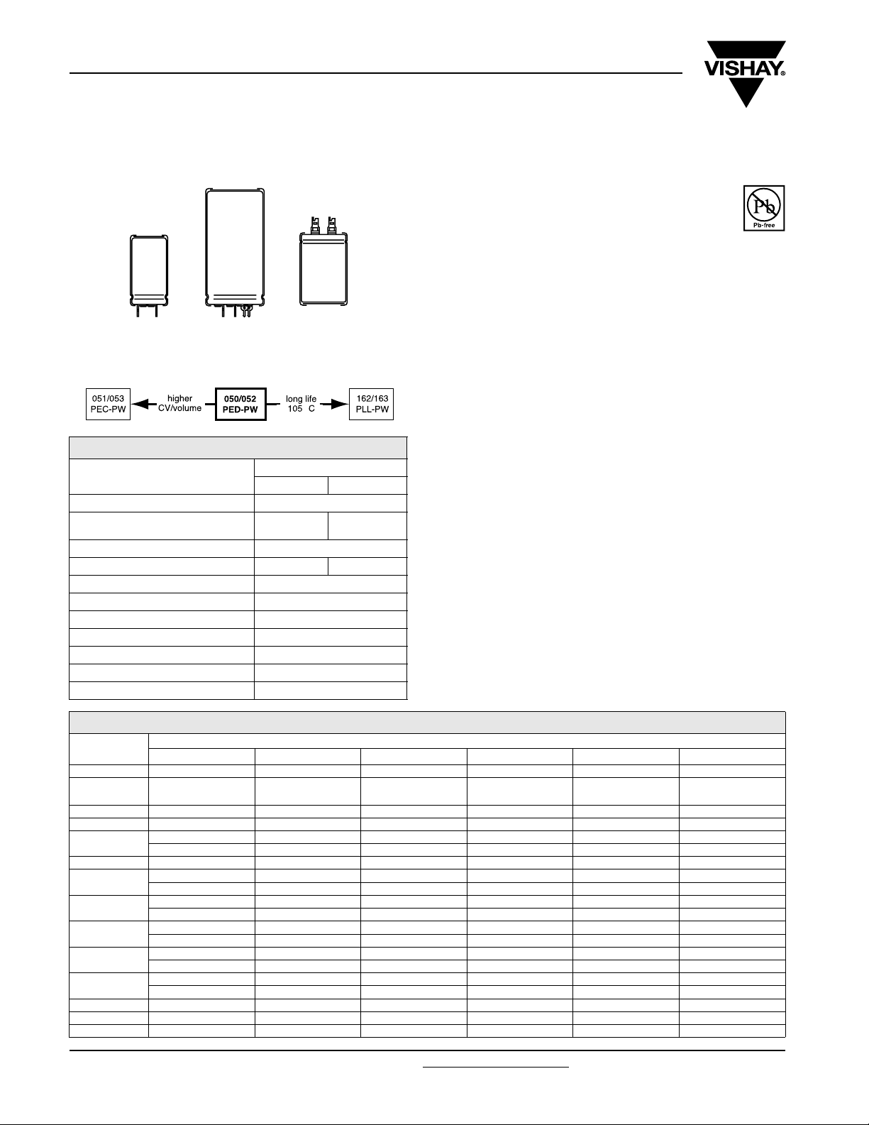
Fig.1 Component outlines
QUICK REFERENCE DATA
DESCRIPTION
Nominal case size (Ø D x L in mm) 25 x 30 to 40 x 100
Rated capacitance range
(E6 series), C
Tolerance on C
Rated voltage range, U
Category temperature range - 40 °C to + 85 °C
Endurance test at 85 °C 5000 hours
Useful life at 85 °C 15 000 hours
Useful life at 40 °C, 1.4 x I
Shelf life at 0 V, 85 °C 500 hours
Based on sectional specification IEC 60384-4/EN130300
Climatic category IEC 60 068 40/085/56
R
R
PW
°
050 052
470 µF
to 68 000 µF
- 10 % to + 30 %
R
R
10 V to 100 V 250 V to 400 V
applied 250 000 hours
SL
VAL UE
47 µF
to 1000 µF
FEATURES
• Polarized aluminum electrolytic capacitors,
non-solid electrolyte
• Large types, cylindrical aluminum case,
insulated with a blue sleeve
• Provided with keyed polarity
RoHS
COMPLIANT
• 050 series also available in solder-lug (SL) versions
• Very long useful life: 15 000 hours at 85 °C
• Low ESR, high ripple current capability
• High resistance to shock and vibration
APPLICATIONS
• Computer, telecommunication and industrial systems
• Smoothing and filtering
• Standard and switched mode power supplies
• Energy storage in pulse systems
MARKING
The capacitors are marked (where possible) with the
following information:
• Rated capacitance (in µF)
• Tolerance on rated capacitance, code letter in accordance
with IEC 60062 (Q for - 10 %/+ 30 %)
• Rated voltage (in V)
• Date code (YYMM)
• Name of manufacturer
• Code for factory of origin
• Polarity of the terminals and ‘-’ sign to indicate the negative
terminal, visible from the top and/or side of the capacitor
• Code number
• Climatic category in accordance with IEC 60068
SELECTION CHART FOR CR, UR AND RELEVANT NOMINAL CASE SIZES FOR 050 SERIES
U
C
R
(µF)
470-----25x30
680----
1000 ----25x3030x40
1500 - - - 25 x 30 25 x 40 35 x 40
2200
3300 - 25 x 30 25 x 40 30 x 40 35 x 40 40 x 50
4700
6800
10 000
15 000
22 000
33 000 40 x 50 40 x 70 40 x 100 - - 47 00040x7040x100---68 00040x100-----
www.vishay.com For technical questions, contact: aluminumcaps2@vishay.com
126 Revision: 10-Mar-09
10 16 25 40 63 100
- - 25 x 30 25 x 40 30 x 40 35 x 50
-----40x40
25 x 30 25 x 40 30 x 40 35 x 40 35 x 50 40 x 70
----40x40-
25 x 40 30 x 40 35 x 40 35 x 50 40 x 50 40 x 100
---40x40--
30 x 40 35 x 40 35 x 50 40 x 50 40 x 70 -
--40x40---
35 x 40 35 x 50 40 x 50 40 x 70 40 x 100 -
-40x40---35 x 50 40 x 50 40 x 70 40 x 100 - 40x40-----
R
(V)
(Ø D x L in mm)
-
Document Number: 28345
25 x 40
Page 3
050/052 PED-PW
Aluminum Capacitors
Vishay BCcomponents
Power Eurodin Printed Wiring
SELECTION CHART FOR CR, UR AND RELEVANT NOMINAL CASE SIZES FOR 052 SERIES (Ø D x L)
U
C
R
(µF)
250 385 400
47 - 25 x 30 25 x 30
68 - 25 x 40 25 x 40
100 25 x 30 30 x 40 30 x 40
150 25 x 40 35 x 40 35 x 40
220
30 x 40 35 x 50 35 x 50
-40x40 40x40
330 35 x 40 40 x 50 40 x 50
470
35 x 50 40 x 70 40 x 70
40 x 40 - -
680 40 x 50 - 40 x 100
1000 40 x 70 - -
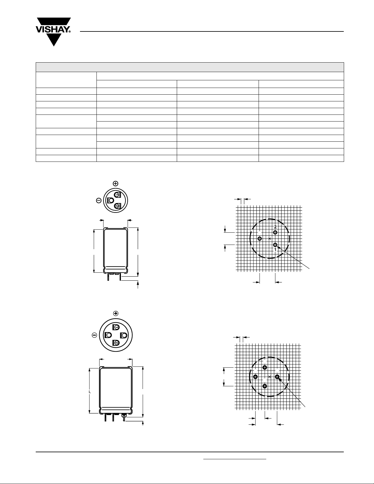
DIMENSIONS in millimeters AND AVAILABLE FORMS
-
R
(V)
2.5
Ø D + 1 max.
L
Case Ø D = 25 mm
Fig.2 Printed wiring pin version
-
Ø D + 1 max.
L + 5 max.
3
4.9 ± 0.2
L + 5 max.
10 ± 0.1
Case Ø D = 25 mm
-
12.5
± 0.1
1.3
(3 x)
Fig.3 Mounting hole diagram viewed from component side
2.5
2
3
1
±
15 0.1
-
1.3
(4 x)
7.5 ± 0.1
Case Ø D = 30 mm
±
17.5 0.1
Case Ø D = 30 mm
Fig.4 Printed wiring pin version
4.9 ± 0.2
Fig.5 Mounting hole diagram viewed from component side
Document Number: 28345 For technical questions, contact: aluminumcaps2@vishay.com
www.vishay.com
Revision: 10-Mar-09 127
Page 4
050/052 PED-PW
Vishay BCcomponents
-
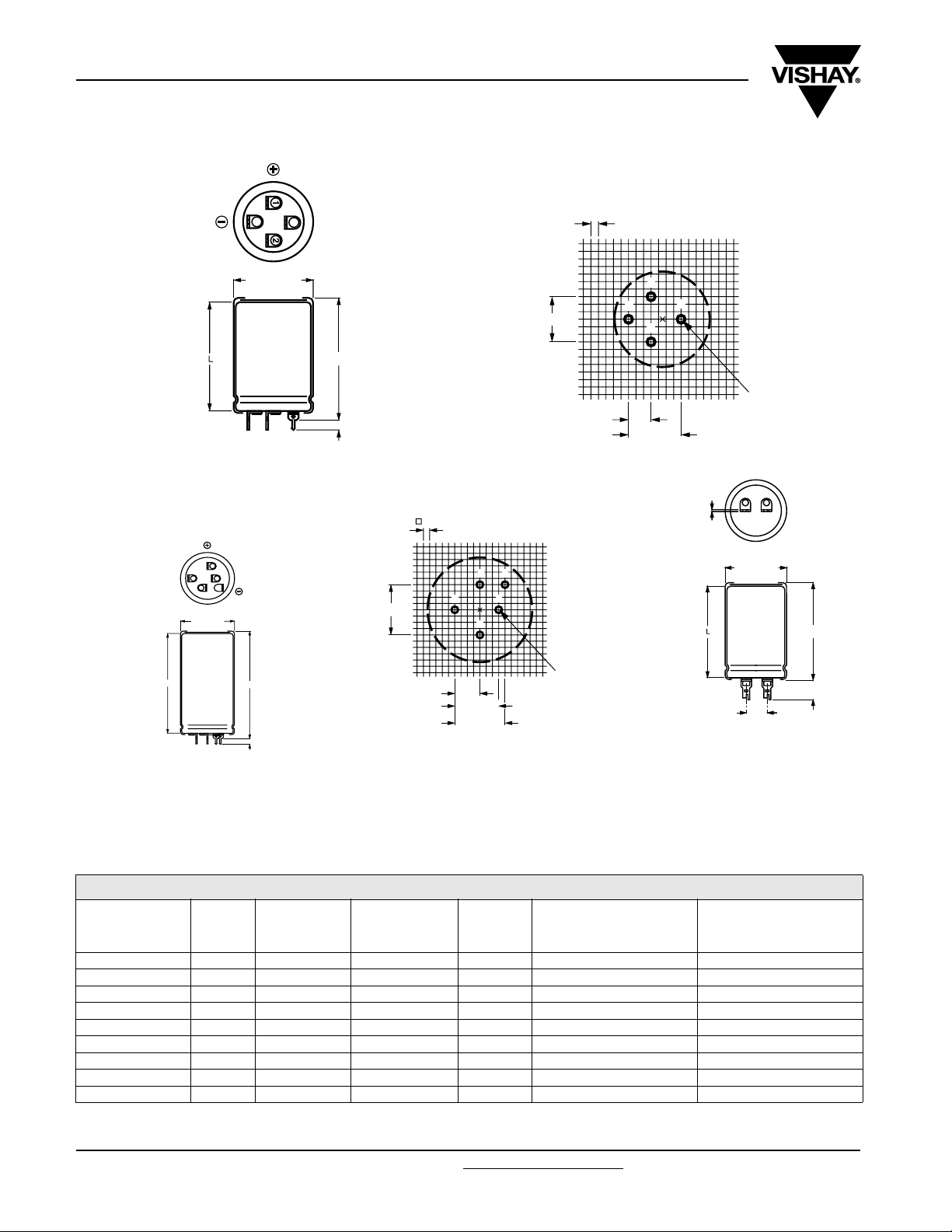
Ø D + 1 max.
Case Ø D = 35 mm
Fig.6 Printed wiring pin version
3
Aluminum Capacitors
Power Eurodin Printed Wiring
L + 5 max.
4.9 ± 0.2
Case Ø D = 35 mm
Fig.7 Mounting hole diagram viewed from component side
2.5
±
15 0.1
2.5
7.5 ± 0.1
2
-
1
±
17.5 0.1
3
1.3
(4 x)
0.8
2
3
Ø D + 1 max.
L
Case Ø D = 40 mm
Fig.8 Printed wiring pin version
1
4
-
20 ± 0.1
L + 5 max.
4.9 ± 0.2
10 ± 0.1
Case Ø D = 40 mm
Fig.9 Mounting hole diagram viewed
34-
2
1
17.5 ± 0.1
20 ± 0.1
1.3
(5 x)
Case Ø D = 40 mm
from component outside
Ø D + 1 max.
L + 2 max.
9 ± 1
10
± 05
Fig.10 Solder-lug version (SL):
only available in 050 series
MOUNTING
When a number of capacitors are connected in a bank, they must not be closer together than 15 mm, when no derating of ripple
current and/or temperature is applied.
Pin numbers 2, 3 and 4 (if present) must be free from the electrical circuit.
Tab l e 1
DIMENSIONS in millimeters, MASS AND PACKAGING QUANTITIES
NOMINAL
CASE SIZE
Ø D x L
Ø D
max.
L
max.
SL VERSIONS
L
max.
PW VERSIONS
MASS
(g)
PACKAGING QUANTITIES
(units per box)
25 x 30 26 32 35 ≈ 24 100 290 x 280 x 50
25 x 40 26 42 45 ≈ 28 100 290 x 280 x 60
30 x 40 31 42 45 ≈ 38 100 340 x 330 x 60
35 x 40 36 42 45 ≈ 51 50 390 x 198 x 60
35 x 50 36 52 55 ≈ 66 50 390 x 198 x 70
(1)
40 x 40
41 - 45 ≈ 78 50 440 x 223 x 60
40 x 50 41 52 55 ≈ 82 50 440 x 223 x 70
40 x 70 41 72 75 ≈ 110 25 230 x 230 x 90
40 x 100 41 102 105 ≈ 176 25 230 x 230 x 120
Note
(1)
Not available in SL versions
www.vishay.com For technical questions, contact: aluminumcaps2@vishay.com
128 Revision: 10-Mar-09
CARDBOARD
BOX DIMENSIONS
L x W x H
Document Number: 28345
Page 5

050/052 PED-PW
Aluminum Capacitors
Vishay BCcomponents
Power Eurodin Printed Wiring
ELECTRICAL DATA
SYMBOL DESCRIPTION
C
R
I
R
I
L1
I
L5
ESR max. equivalent series resistance at 100 Hz
Z max. impedance at 10 kHz
Note
• Unless otherwise specified, all electrical values in tables 2 and 3
apply at T
Tab l e 2
rated capacitance at 100 Hz
rated RMS ripple current at 100 Hz,
85 °C or at 20 kHz, 70 °C
max. leakage current after 1 minute at U
max. leakage current after 5 minutes at U
= 20 °C, P = 86 kPa to 106 kPa, RH = 45 % to 75 %
amb
R
R
ELECTRICAL DATA AND ORDERING INFORMATION FOR 050 SERIES
R
NOMINAL
CASE SIZE
Ø D x L
(mm)
U
R
(V)
10
16
25
40 6800 35 x 50 4.7 8.9 1.64 0.55 36 27 17682E3 57682E3
C
100 Hz
(µF)
4700 25 x 30 2.4 4.6 0.28 0.10 74 50 14472E3 54472E3
6800 25 x 40 3.2 6.1 0.41 0.14 51 37 14682E3 54682E3
10 000 30 x 40 3.8 7.2 0.60 0.20 39 29 14103E3 54103E3
15 000 35 x 40 4.1 7.8 0.90 0.30 35 26 14153E3 54153E3
22 000 35 x 50 5.0 9.5 1.32 0.44 27 21 14223E3 54223E3
22 000 40 x 40 4.2 8.0 1.32 0.44 36 27 not available 44223E3
33 000 40 x 50 5.0 9.5 1.98 0.66 29 22 14333E3 54333E3
47 000 40 x 70 6.8 12.9 2.82 0.94 20 17 14473E3 54473E3
68 000 40 x 100 9.2 17.5 4.08 1.36 15 14 14683E3 54683E3
3300 25 x 30 2.4 4.6 0.32 0.11 75 50 15332E3 55332E3
4700 25 x 40 3.1 5.9 0.45 0.15 52 37 15472E3 55472E3
6800 30 x 40 3.7 7.0 0.65 0.22 40 30 15682E3 55682E3
10 000 35 x 40 4.1 7.8 0.96 0.32 36 27 15103E3 55103E3
15 000 35 x 50 5.0 9.5 1.44 0.48 28 21 15153E3 55153E3
15 000 40 x 40 4.2 8.0 1.44 0.48 36 27 not available 45153E3
22 000 40 x 50 5.0 9.5 2.12 0.71 29 22 15223E3 55223E3
33 000 40 x 70 6.7 12.7 3.17 1.06 20 17 15333E3 55333E3
47 000 40 x 100 9.1 17.3 4.51 1.51 15 14 15473E3 55473E3
2200 25 x 30 2.3 4.4 0.33 0.11 78 52 16222E3 56222E3
3300 25 x 40 3.1 5.9 0.49 0.17 53 38 16332E3 56332E3
4700 30 x 40 3.7 7.0 0.70 0.24 42 31 16472E3 56472E3
6800 35 x 40 4.1 7.8 1.02 0.34 37 28 16682E3 56682E3
10 000 35 x 50 5.0 9.5 1.50 0.50 28 21 16103E3 56103E3
10 000 40 x 40 4.2 8.0 1.50 0.50 36 27 not available 46103E3
15 000 40 x 50 5.0 9.5 2.25 0.75 29 22 16153E3 56153E3
22 000 40 x 70 6.8 12.9 3.30 1.10 20 17 16223E3 56223E3
33 000 40 x 100 9.2 17.5 4.95 1.65 15 14 16333E3 56333E3
1500 25 x 30 2.0 3.8 0.36 0.12 112 68 17152E3 57152E3
2200 25 x 40 2.7 5.1 0.53 0.18 76 51 17222E3 57222E3
3300 30 x 40 3.3 6.3 0.79 0.27 57 41 17332E3 57332E3
4700 35 x 40 3.8 7.2 1.13 0.38 48 35 17472E3 57472E3
6800 40 x 40 4.1 7.8 1.64 0.55 45 33 not available 47682E3
10 000 40 x 50 4.9 9.3 2.40 0.80 35 27 17103E3 57103E3
15 000 40 x 70 6.6 12.5 3.60 1.20 25 20 17153E3 57153E3
22 000 40 x 100 9.0 17.1 5.28 1.76 18 16 17223E3 57223E3
I
R
100 Hz
85 °C
(A)
I
R
20 kHz
70 °C
(A)
I
L1
1min
(mA)
ORDERING EXAMPLE
Electrolytic capacitor 050 series
10 000 µF/25 V; - 10/+ 30 %
Nominal case size: Ø 35 x 50 mm; PW version
Ordering code: MAL2050 56103 E3
Former 12NC: 2222050 56103
I
L5
5min
(mA)
ESR
100 Hz
(mΩ)
Z
10 kHz
(mΩ)
ORDERING
CODE SL
MAL2050.......
ORDERING
CODE PW
MAL2050.......
Document Number: 28345 For technical questions, contact: aluminumcaps2@vishay.com
Revision: 10-Mar-09 129
www.vishay.com
Page 6

050/052 PED-PW
Vishay BCcomponents
Aluminum Capacitors
Power Eurodin Printed Wiring
ELECTRICAL DATA AND ORDERING INFORMATION FOR 050 SERIES
I
R
100 Hz
85 °C
(A)
I
R
20 kHz
70 °C
(A)
I
L1
1min
(mA)
I
L5
5min
(mA)
ESR
100 Hz
(mΩ)
Z
10 kHz
(mΩ)
U
(V)
63
100
C
R
R
100 Hz
(µF)
1000 25 x 30 1.8 3.4 0.38 0.13 122 74 18102E3 58102E3
1500 25 x 40 2.5 4.7 0.57 0.19 83 54 18152E3 58152E3
2200 30 x 40 3.1 5.9 0.83 0.28 57 41 18222E3 58222E3
3300 35 x 40 3.6 6.8 1.25 0.42 48 35 18332E3 58332E3
4700 35 x 50 4.4 8.3 1.78 0.60 36 27 18472E3 58472E3
4700 40 x 40 3.8 7.2 1.78 0.60 45 33 not available 48472E3
6800 40 x 50 4.7 8.9 2.57 0.86 35 27 18682E3 58682E3
10 000 40 x 70 6.2 11.8 3.78 1.26 25 20 18103E3 58103E3
15 000 40 x 100 8.5 16.1 5.67 1.89 18 16 18153E3 58153E3
470 25 x 30 1.4 2.7 0.28 0.10 247 172 19471E3 59471E3
680 25 x 40 1.9 3.6 0.41 0.14 170 116 19681E3 59681E3
1000 30 x 40 2.5 4.7 0.60 0.20 123 88 19102E3 59102E3
1500 35 x 40 3.1 5.8 0.90 0.30 94 71 19152E3 59152E3
2200 35 x 50 3.9 7.4 1.32 0.44 69 55 19222E3 59222E3
2200 40 x 40 3.6 6.8 1.32 0.44 81 65 not available 49222E3
3300 40 x 50 4.6 8.7 1.98 0.66 59 48 19332E3 59332E3
4700 40 x 70 6.2 11.7 2.82 0.94 42 36 19472E3 59472E3
6800 40 x 100 8.2 15.5 4.08 1.36 32 28 19682E3 59682E3
NOMINAL
CASE SIZE
Ø D x L
(mm)
ORDERING
CODE SL
MAL2050.......
ORDERING
CODE PW
MAL2050.......
Tab l e 3
ELECTRICAL DATA AND ORDERING INFORMATION FOR 052 SERIES
C
U
R
(V)
250
385
400
www.vishay.com For technical questions, contact: aluminumcaps2@vishay.com
130 Revision: 10-Mar-09
R
100 Hz
(µF)
100 25 x 30 0.6 1.15 0.15 0.05 1800 1300 53101E3
150 25 x 40 0.8 1.5 0.23 0.08 1100 850 53151E3
220 30 x 40 1.0 1.9 0.33 0.11 750 550 53221E3
330 35 x 40 1.4 2.65 0.49 0.17 500 400 53331E3
470 35 x 50 1.8 3.4 0.70 0.24 360 290 53471E3
470 40 x 40 1.8 3.4 0.70 0.24 420 350 43471E3
680 40 x 50 2.3 4.4 1.02 0.34 250 190 53681E3
1000 40 x 70 3.0 5.7 1.50 0.50 170 140 53102E3
47 25 x 30 0.5 0.94 0.11 0.04 2370 1550 58479E3
68 25 x 40 0.67 1.27 0.16 0.06 1 640 1100 58689E3
100 30 x 40 0.84 1.59 0.23 0.08 1 275 950 58101E3
150 35 x 40 1.13 2.14 0.34 0.11 850 635 58151E3
220 35 x 50 1.48 2.8 0.50 0.17 580 430 58221E3
220 40 x 40 1.48 2.8 0.50 0.17 580 430 48221E3
330 40 x 50 1.97 3.73 0.75 0.25 385 300 58331E3
470 40 x 70 2.7 5.11 1.06 0.36 270 215 58471E3
47 25 x 30 0.47 0.89 0.11 0.04 2 700 2125 56479E3
68 25 x 40 0.63 1.29 0.16 0.06 1 875 1470 56689E3
100 30 x 40 0.84 1.59 0.24 0.08 1 275 1000 56101E3
150 35 x 40 1.13 2.14 0.36 0.12 850 665 56151E3
220 35 x 50 1.41 2.67 0.52 0.17 650 450 56221E3
220 40 x 40 1.41 2.67 0.52 0.17 650 450 46221E3
330 40 x 50 1.86 3.52 0.79 0.26 435 315 56331E3
470 40 x 70 2.54 4.81 1.12 0.37 305 225 56471E3
680 40 x 100 3.56 6.75 1.63 0.54 210 155 56681E3
NOMINAL
CASE SIZE
Ø D x L
(mm)
I
R
100 Hz
85 °C
(A)
I
R
20 kHz
70 °C
(A)
I
L1
1min
(mA)
I
L5
5min
(mA)
ESR
100 Hz
(mΩ)
Z
10 kHz
(mΩ)
Document Number: 28345
ORDERING
CODE
MAL2052.......
Page 7

050/052 PED-PW
Aluminum Capacitors
Vishay BCcomponents
Power Eurodin Printed Wiring
ADDITIONAL ELECTRICAL DATA
PARAMETER CONDITIONS VALUE
Voltage
Surge voltage
≤ 250 V versions U
≥ 385 V versions Us= 1.1 x U
Reverse voltage U
Current
Leakage current
After 1 minute at U
After 5 minutes at U
R
R
Inductance
Case Ø D = 25 mm max. 25 nH
Equivalent series inductance (ESL)
Case Ø D = 30 and 35 mm max. 30 nH
Case Ø D = 40 mm max. 35 nH
CAPACITANCE (C) EQUIVALENT SERIES RESISTANCE (ESR)
1.2
C
C
Curve 1: 10 V
0
Curve 2: 25 V
1.1
Curve 3: 63 V
Curve 4: 100 V, 250 V, 385 V
1.0
0.9
0.8
0.7
0.6
- 60 - 40 - 20 0 20 40 60 80
4
3
2
1
C0 = capacitance at 20 °C, 100 Hz
Fig.11 Typical multiplier of capacitance as a function
of ambient temperature
1
2
3
4
T
(°C)
amb
4
10
ESR
(mΩ)
3
10
10
10
1
1
2
3
4
5
2
6
7
8
9
ESR at 100 Hz and UR = 10 V
- 50 0 50 100
Fig.12 Typical ESR as a function of temperature
= 1.15 x U
s
rev
≤ 1V
R
R
IL1≤ 0.006 CR x UR+4µA
IL5≤ 0.002 CR x UR+4µA
Curve 1: case Ø D x L = 25 x 30 mm
Curve 2: case Ø D x L = 25 x 40 mm
Curve 3: case Ø D x L = 39 x 40 mm
Curve 4: case Ø D x L = 35 x 40 mm
Curve 5: case Ø D x L = 40 x 40 mm
Curve 6: case Ø D x L = 35 x 50 mm
Curve 7: case Ø D x L = 40 x 50 mm
Curve 8: case Ø D x L = 40 x 70 mm
Curve 9: case Ø D x L = 40 x 100 mm
T
(°C)
amb
4
10
ESR
(mΩ)
10
10
10
1
1
3
2
3
4
5
6
7
2
8
9
ESR at 100 Hz and UR = 63 V
- 50 0 50 100
Curve 1: case Ø D x L = 25 x 30 mm
Curve 2: case Ø D x L = 25 x 40 mm
Curve 3: case Ø D x L = 39 x 40 mm
Curve 4: case Ø D x L = 35 x 40 mm
Curve 5: case Ø D x L = 40 x 40 mm
Curve 6: case Ø D x L = 35 x 50 mm
Curve 7: case Ø D x L = 40 x 50 mm
Curve 8: case Ø D x L = 40 x 70 mm
Curve 9: case Ø D x L = 40 x 100 mm
Fig.13 Typical ESR as a function of temperature
T
(°C)
amb
4
10
ESR
(mΩ)
10
10
10
1
1
2
3
4
5
3
6
7
8
9
2
ESR at 100 Hz and UR = 100 V
- 50 0 50 100
Curve 1: case Ø D x L = 25 x 30 mm
Curve 2: case Ø D x L = 25 x 40 mm
Curve 3: case Ø D x L = 39 x 40 mm
Curve 4: case Ø D x L = 35 x 40 mm
Curve 5: case Ø D x L = 40 x 40 mm
Curve 6: case Ø D x L = 35 x 50 mm
Curve 7: case Ø D x L = 40 x 50 mm
Curve 8: case Ø D x L = 40 x 70 mm
Curve 9: case Ø D x L = 40 x 100 mm
Fig.14 Typical ESR as a function of temperature
T
(°C)
amb
Document Number: 28345 For technical questions, contact: aluminumcaps2@vishay.com
www.vishay.com
Revision: 10-Mar-09 131
Page 8

050/052 PED-PW
Vishay BCcomponents
Aluminum Capacitors
Power Eurodin Printed Wiring
EQUIVALENT SERIES RESISTANCE (ESR) IMPEDANCE (Z)
5
10
ESR
(mΩ)
10
10
10
4
3
2
Curve 1: case Ø D x L = 25 x 30 mm
Curve 2: case Ø D x L = 25 x 40 mm
Curve 3: case Ø D x L = 39 x 40 mm
Curve 4: case Ø D x L = 35 x 40 mm
Curve 5: case Ø D x L = 40 x 40 mm
Curve 6: case Ø D x L = 35 x 50 mm
Curve 7: case Ø D x L = 40 x 50 mm
Curve 8: case Ø D x L = 40 x 70 mm
ESR at 100 Hz and UR = 385 V
10
- 50 0 50 100
Fig.15 Typical ESR as a function of temperature
3
10
Z
(mΩ)
10
1
2
3
4
2
5
6
7
8
Curve 1: case Ø D x L = 25 x 30 mm
Curve 2: case Ø D x L = 25 x 40 mm
Curve 3: case Ø D x L = 39 x 40 mm
Curve 4: case Ø D x L = 35 x 40 mm
Curve 5: case Ø D x L = 40 x 40 mm
Curve 6: case Ø D x L = 35 x 50 mm
Curve 7: case Ø D x L = 40 x 50 mm
Curve 8: case Ø D x L = 40 x 70 mm
1
2
3
4
5
6
7
8
T
(°C)
amb
3
10
Z
(mΩ)
10
1
2
3
2
4
5
6
7
8
10
Z = at 10 kHz and UR = 10 V
1
- 50 0 50 100
Fig.16 Typical impedance as a function of temperature
4
10
Z
(mΩ)
10
10
3
2
1
2
3
4
5
6
7
8
Curve 1: case Ø D x L = 25 x 30 mm
Curve 2: case Ø D x L = 25 x 40 mm
Curve 3: case Ø D x L = 39 x 40 mm
Curve 4: case Ø D x L = 35 x 40 mm
Curve 5: case Ø D x L = 40 x 40 mm
Curve 6: case Ø D x L = 35 x 50 mm
Curve 7: case Ø D x L = 40 x 50 mm
Curve 8: case Ø D x L = 40 x 70 mm
T
(°C)
amb
Curve 1: case Ø D x L = 25 x 30 mm
Curve 2: case Ø D x L = 25 x 40 mm
Curve 3: case Ø D x L = 39 x 40 mm
Curve 4: case Ø D x L = 35 x 40 mm
Curve 5: case Ø D x L = 40 x 40 mm
Curve 6: case Ø D x L = 35 x 50 mm
Curve 7: case Ø D x L = 40 x 50 mm
Curve 8: case Ø D x L = 40 x 70 mm
10
Z = at 10 kHz and UR = 63 V
1
- 50 0 50 100
Fig.17 Typical impedance as a function of temperature
5
10
Z
(mΩ)
10
10
10
4
3
2
Z = at 10 kHz and U
Curve 1: case Ø D x L = 25 x 30 mm
Curve 2: case Ø D x L = 25 x 40 mm
Curve 3: case Ø D x L = 39 x 40 mm
Curve 4: case Ø D x L = 35 x 40 mm
Curve 5: case Ø D x L = 40 x 40 mm
Curve 6: case Ø D x L = 35 x 50 mm
Curve 7: case Ø D x L = 40 x 50 mm
Curve 8: case Ø D x L = 40 x 70 mm
= 385 V
R
10
- 50 0 50 100
Fig.19 Typical impedance as a function of temperature
10
Z = at 10 kHz and UR = 100 V
1
- 50 0 50 100
T
T
(°C)
amb
Fig.18 Typical impedance as a function of temperature
2
( )
10
Z
Ω
10
1
2
3
Curve 1: 47 µF, 3 85 V
Curve 2: 100 µF, 250 V
Curve 3: 470 µF, 100 V
Curve 4: 1000 µF, 63 V
Curve 5: 4700 µF, 10 V
amb
(°C)
4
1
1
2
3
4
5
6
7
8
T
(°C)
amb
-1
10
-2
10
5
Case Ø D x L = 25 x 30 mm
2
10 10
103 10
4 105
106 10
f (Hz)
T
(20 °C)
amb
7
Fig.20 Typical impedance as a function of temperature
www.vishay.com For technical questions, contact: aluminumcaps2@vishay.com
Document Number: 28345
132 Revision: 10-Mar-09
Page 9

050/052 PED-PW
IMPEDANCE (Z)
2
10
( )
( )
Z
Ω
10
10
10
10
Z
Ω
10
1
2
3
4
1
5
-1
Case Ø D x L = 25 x 40 mm
-2
2
10 10
103 10
Fig.21 Typical impedance as a function of frequency
2
1
2
Aluminum Capacitors
Power Eurodin Printed Wiring
Curve 1: 68 µF, 3 85 V
Curve 2: 150 µF, 250 V
Curve 3: 680 µF, 100 V
Curve 4: 1500 µF, 63 V
Curve 5: 6800 µF, 10 V
4 105
Curve 1: 150 µF, 3 85 V
Curve 2: 330 µF, 250 V
Curve 3: 1500 µF, 100 V
Curve 4: 3300 µF, 63 V
Curve 5: 15 000 µF, 10 V
106 10
f (Hz)
7
2
10
( )
Z
Ω
10
1
2
3
4
1
5
-1
10
Case Ø D x L = 35 x 40 mm
-2
10
10 10
Fig.22 Typical impedance as a function of frequency
2
10
Z
Ω
( )
10
1
2
Vishay BCcomponents
2
103 10
Curve 1: 47 µF, 3 85 V
Curve 2: 220 µF, 250 V
Curve 3: 1000 µF, 100 V
Curve 4: 2200 µF, 63 V
Curve 5: 10 000 µF, 10 V
4 105
Curve 1: 220 µF, 3 85 V
Curve 2: 470 µF, 250 V
Curve 3: 2200 µF, 100 V
Curve 4: 4700 µF, 63 V
Curve 5: 22 000 µF, 10 V
106 10
f (Hz)
7
3
1
4
5
-1
10
Case Ø D x L = 35 x 40 mm
-2
10
10 10
Fig.23 Typical impedance as a function of frequency
2
10
Z
Ω
( )
10
10
10
1
2
3
1
4
-1
-2
5
Case Ø D x L = 40 x 40 mm
10 10
2
103 10
2
103 10
4 105
Curve 1: 220 µF, 3 85 V
Curve 2: 470 µF, 250 V
Curve 3: 2200 µF, 100 V
Curve 4: 4700 µF, 63 V
Curve 5: 22 000 µF, 10 V
4 105
106 10
f (Hz)
106 10
f (Hz)
3
1
4
-1
10
10
7
5
Case Ø D x L = 35 x 50 mm
-2
2
10 10
103 10
4 105
106 10
f (Hz)
7
Fig.24 Typical impedance as a function of frequency
2
10
Z
Ω
( )
10
1
2
1
3
4
-1
10
10
7
5
Case Ø D x L = 40 x 50 mm
-2
2
10 10
103 10
Curve 1: 330 µF, 3 85 V
Curve 2: 250 µF, 250 V
Curve 3: 3300 µF, 100 V
Curve 4: 6800 µF, 63 V
Curve 5: 33 000 µF, 10 V
4 105
106 10
f (Hz)
7
Fig.25 Typical impedance as a function of frequency
Fig.26 Typical impedance as a function of frequency
Document Number: 28345 For technical questions, contact: aluminumcaps2@vishay.com
www.vishay.com
Revision: 10-Mar-09 133
Page 10

050/052 PED-PW
Vishay BCcomponents
Power Eurodin Printed Wiring
IMPEDANCE (Z)
2
10
Case Ø D x L = 40 x 70 mm
Z
Ω
( )
10
10
10
1
-1
-2
10 10
1
2
3
4
5
2
103 10
Fig.27 Typical impedance as a function of frequency
RIPPLE CURRENT AND USEFUL LIFE
Curve 1: 470 µF, 3 85 V
Curve 2: 1000 µF, 250 V
Curve 3: 4700 µF, 100 V
Curve 4: 10 000 µF, 63 V
Curve 5: 47 000 µF, 10 V
4 105
Aluminum Capacitors
2
10
Z
Ω
( )
10
1
-1
10
-2
10
10 10
106 10
f (Hz)
7
Curve 1: 6800 µF, 100 V
Curve 2: 15 000 µF, 63 V
Curve 3: 68 000 µF
1
2
3
Case Ø D x L = 40 x 100 mm
2
103 10
4 105
106 10
Fig.28 Typical impedance as a function of frequency
f (Hz)
7
IA = actual ripple current
= rated ripple current at 100 Hz and 85 °C
I
R
(1)
Useful life at 85 °C and IR applied: 15 000 hours
2.4
2.3
I
A
I
R
2.2
2.1
2.0
1.9
1.8
1.7
1.6
1.5
1.4
1.3
1.2
1.1
1.0
0.8
0.5
0.0
30
45
60
40 50 60 70 8090
8
10
15
20
2.5
3
4
5
1
1.2
1.5
2
life multiplier
MGA453
(1)
T
(°C)
amb
Fig.29 Multiplier of useful life as a function of ambient temperature and ripple current load.
www.vishay.com For technical questions, contact: aluminumcaps2@vishay.com
Document Number: 28345
134 Revision: 10-Mar-09
Page 11

050/052 PED-PW
Aluminum Capacitors
Vishay BCcomponents
Power Eurodin Printed Wiring
Tab l e 4
MULTIPLIER OF RIPPLE CURRENT (IR) AS A FUNCTION OF FREQUENCY
MULTIPLIER
FREQUENCY (Hz)
50 0.83
100 1.00
200 1.10
400 1.15
1000 1.19
≥ 2000 1.20
Tab l e 5
TEST PROCEDURES AND REQUIREMENT
TEST
NAME OF TEST REFERENCE
Endurance IEC 60384-4/
EN130300
subclause 4.13
Useful life CECC 30301
subclause 1.8.1
Shelf life
(storage at
high temperature)
IEC 60384-4/
EN130300
subclause 4.17
= 85 °C; UR applied;
T
amb
5000 hours
T
= 85 °C; UR and IR applied;
amb
15 000 hours
= 85 °C; no voltage applied;
T
amb
500 hours
after test: U
24 hours to 48 hours before measurement
PROCEDURE
(quick reference)
to be applied for 30 minutes,
R
I
R
UR≤ 100 V; ΔC/C: ± 15 %
U
> 100 V; ΔC/C: ± 10 %
R
ESR ≤ 1.3 x spec. limit
Z ≤ x 2 spec. limit
I
≤ spec. limit
L5
UR≤ 100 V; ΔC/C: ± 45 %
U
> 100 V; ΔC/C: ± 30 %
R
ESR ≤ 3 x spec. limit
Z ≤ 3 x spec. limit
I
≤ spec. limit
L5
no short or open circuit,
no visible damage
total failure percentage:
≤ 100 V: ≤ 1 %;
U
R
> 100 V: ≤ 3 %
U
R
ΔC/C: ± 10 %
ESR ≤ 1.2 x spec. limit
≤ 2 x spec. limit
I
L5
REQUIREMENTS
Document Number: 28345 For technical questions, contact: aluminumcaps2@vishay.com
Revision: 10-Mar-09 135
www.vishay.com
Page 12

Legal Disclaimer Notice
Vishay
Disclaimer
All product specifications and data are subject to change without notice.
Vishay Intertechnology, Inc., its affiliates, agents, and employees, and all persons acting on its or their behalf
(collectively, “Vishay”), disclaim any and all liability for any errors, inaccuracies or incompleteness contained herein
or in any other disclosure relating to any product.
Vishay disclaims any and all liability arising out of the use or application of any product described herein or of any
information provided herein to the maximum extent permitted by law. The product specifications do not expand or
otherwise modify Vishay’s terms and conditions of purchase, including but not limited to the warranty expressed
therein, which apply to these products.
No license, express or implied, by estoppel or otherwise, to any intellectual property rights is granted by this
document or by any conduct of Vishay.
The products shown herein are not designed for use in medical, life-saving, or life-sustaining applications unless
otherwise expressly indicated. Customers using or selling Vishay products not expressly indicated for use in such
applications do so entirely at their own risk and agree to fully indemnify Vishay for any damages arising or resulting
from such use or sale. Please contact authorized Vishay personnel to obtain written terms and conditions regarding
products designed for such applications.
Product names and markings noted herein may be trademarks of their respective owners.
Document Number: 91000 www.vishay.com
Revision: 18-Jul-08 1
 Loading...