

C&H Technologies M222 User Manual

USER’S MANUAL
4 CHANNEL
FORM-C
POWER RELAY
M-MODULE
MODEL
M222
( FORMERLY
HP E2274 A )
C&H Technologies, Inc. <> 445 Round Rock West Drive <> Round Rock, TX 78681 <> www.chtech.com
Document Part No: 11029574

COPYRIGHT
C&H Technologies, Inc. (C&H) provides this manual "as is" without warranty of any kind, either
expressed or implied, including but not limited to the implied warranties of merchantability and
fitness for a particular purpose. C&H may make improvements and/or changes in the product(s)
and/or program(s) described in this manual at any time and without notice.
This publication could contain technical inaccuracies or typographical errors. Changes are
periodically made to the information herein; these changes will be incorporated in new editions of
this publication.
Copyright © 2007 by C&H Technologies, Inc.
Portions of this manual have been copied from relevant Hewlett-Packard (Agilent) User Manual’s
with their expressed written permiss ion. The information and/or drawings set forth in this
document and all rights in and to inventions disclosed herein which might be granted thereon
disclosing or employi ng the materials, methods, techniques, or apparatus described herein, are the
exclusive property of C&H Technologies, Inc.
A Reader's Comment Form is provided at the back of this publication. If this form has been
removed address comments to:
C&H Technologies, Inc.
Technical Publications
445 Round Rock West Drive
C&H Technologies, Inc. <> 445 Round Rock West Drive <> Round Rock, TX 78681 <> www.chtech.com
Austin, Texas 78681-5012
Or visit our web site for support information at:
http://www.chtech.com.
C&H may use or distribute any of the information you supply in any way that it believes appropriate without incurring any obligations.
ii

AMENDMENT NOTICE
C&H Technologies, Inc. makes every attempt to provide up-to-date manuals with the associated
equipment. Occasionally, changes are made to the equipment wherein it is necessary to provide
amendments to the manual . If any amendments are provided for this manual they are printed on
colored paper and will be provided with the module and manual. Manual updates may also be
found on out web site at www.chtech.com.
NOTE
The contents of any amendment may affect operation, maintenance,
or calibration of the equipment.
C&H Technologies, Inc. <> 445 Round Rock West Drive <> Round Rock, TX 78681 <> www.chtech.com
iii

INTRODUCTION
This manual describes the operation and use of the C&H Model M222 4 Channel Form C Power
Relay M-Module (Part Number 11029570). This module was formerly manufactured by HP
(Agilent) as Model E 2274A. C&H obtained the manufacturing rights from Agilent and now
manufacturers it as C&H Model M222. This mezzanine module is designed to interface within
any M/MA-Module carrier adhering t o the ANSI/VITA 12-1996 M-Module specification. These
carriers are available in man y formats such as Ethernet, VME, VXI, PXI, cPCI, and the PC.
Contained within this manual are the physical and electrical specifications, installation and startup
procedures, functional descriptio n, and configuration and pro gramming guidelines to adequately
use the product.
This manual is based on a low level register access, and is written in such a manner t o provide
understandi ng to the user based on this type of access. If a driver is provided, please refer to the
driver documentation for instruction using the higher leve l interface provided by the driver.
C&H Technologies, Inc. <> 445 Round Rock West Drive <> Round Rock, TX 78681 <> www.chtech.com
iv

TABLE OF CONTENTS
1.0 GENERAL DESCRIPTION................................................................................................ 1
1.1 PURPOSE OF EQUIPMENT ................................................................ ................... 1
1.2 SPECIFICATIONS OF EQUIPMENT................................ ................................ ...... 1
1.2.1 Key Features............................................................................................ 1
1.2.2 Specifications........................................................................................... 2
1.2.3 Mechanical................................ ................................ ............................... 3
1.2.4 Bus Compliance....................................................................................... 3
1.2.5 Applicable Documents.............................................................................. 3
2.0 INSTALLATION................................................................................................................ 5
2.1 UNPACKING AND INSPECTION .......................................................................... 5
2.2 HANDLING PRECAUTIONS.................................................................................. 5
2.3 INSTALLATION OF M/MA MODULES................................................................. 5
2.4 PREPARATION FOR RESHIPMENT...................................................................... 6
3.0 FUNCTIONAL DESCRIPTION ......................................................................................... 7
3.1 OVERVIEW................................................................ ................................ ............. 7
3.1.1 M-Module Interface................................ ................................................. 7
3.1.2 ID EEPROM............................................................................................7
3.2 IDENTIFICATION AND CONFIGURATION REGISTERS ................................... 8
3.2.1 I/O Registers................................ ............................................................ 8
3.2.2 Module Identification............................................................................. 10
4.0 OPERATION.................................................................................................................... 11
4.1 RELAY OPEN/CLOSE................................................................ ........................... 11
4.2 INTERRUPTS........................................................................................................ 11
APPENDIX A: CONNECTORS ............................................................................................ A-1
C&H Technologies, Inc. <> 445 Round Rock West Drive <> Round Rock, TX 78681 <> www.chtech.com
v

LIST OF FIGURES
Figure 1. M-MODULE Installation............................................................................................5
Figure 2. Switching Schematic ...................................................................................................7
Figure 3. I/O Registers...............................................................................................................9
Figure 4. Effects of Opening/Closing Relay................................ ................................ ..............11
Figure A-1. Front Panel I/O Signals.........................................................................................A-1
LIST OF TABLES
Table I. Specifications................................................................................................ ................2
Table II. I/O Address Map/Command Summary.........................................................................8
Table III. M/MA Module PROM IDENT Words......................................................................10
C&H Technologies, Inc. <> 445 Round Rock West Drive <> Round Rock, TX 78681 <> www.chtech.com
vi

1.0 GENERAL DESCRIPTION
The M222 provides 4 individual Form C (SPDT) channels for general purpose switching and
control of external devices on a single wide M-Module adhering to the ANSI/VITA 12-1996
specifi cation for M-Modules. With its 5 ADC per channel current rating, it can be used to switch
external power supplies. The module may be installed on any carrier board supporting the MModule specifi cation. Carriers are available that allow the module to be used in Ethernet (LXI),
VXI, VME, PCI, cPCI, PXI and other system architectures.
1.1 PURPOSE OF EQUIPMENT
The M222 can connect multiple instruments to multiple points in your test system. This provides
flexible interconnection between test points, instrumentation, factory automation, and test
fixtures.
CAUTION: This module DOES NOT have provisions for on-board current
limiting components (if input current can exceed 5A DC or 5A
AC, you must install external current limiting circuitry)
1.2 SPECIFICATIONS OF EQUIPMENT
1.2.1 Key Features
Four (4) Individual Form C (SPDT) Power Relays
Non-latching Relays
Single-wide M module provides high density and maximum flexibility of configuration
C&H Technologies, Inc. <> 445 Round Rock West Drive <> Round Rock, TX 78681 <> www.chtech.com
1
1.2.2 Specifications
The M222 incorporates the standard 40-pin, 20x2 row connector interfaces to the carrier board
for power and data/control, but does not have the 24-pin optional connector for carrying userconnections back onto the carrier board.
The user input/output is provided through a standard 44-pin D-subm iniature female receptacle. A
mating connector kit can be ordered separately as AM111 (C&H Part Number 11029700-0001).
CONEC part number 302A10889X (or equivalent) is used on the assembly. The connector pinouts are shown in Appendix A.
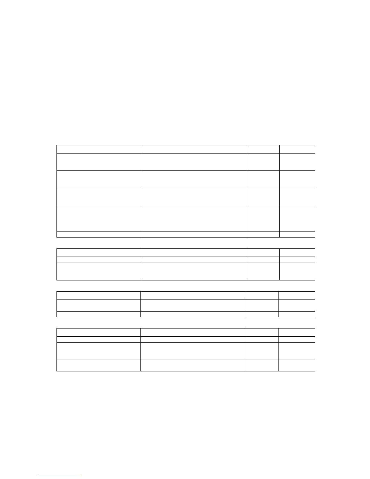
Table I. Specifications
MAXIMUM RATINGS
Parameter Condition Rating Units
Voltage Clean room Environment
(any terminal to any other terminal)
Non-Clean room Environment
(any terminal to any other terminal)
Current (non-inductive) Per Switch, DC
Per Switch, AC
Per Switch, AC
Power Per Switch, DC
Per Switch, AC
Per Module, DC
Per Module, AC
Thermal Offset < 20 µV typ
125
141
200
60
43
68
5
3.53
5
100
100
300
300
VDC
VAC rms
VAC peak
VDC
VAC rms
VAC peak
A
A rms
A peak
W
VA
W
VA
RESISTANCE
Parameter Condition Rating Units
Closed Channel End of Life < 2
Insulation Between any two points
≤40°C, ≤65% relative humidity
≤25°C, ≤40% relative humidity
108
108
typ
typ.
RELAYS
Parameter Condition Rating Units
Relay Life No load
Rated load
Time to open/close register programming 16 ms
5 x 10
3.5 x 10
7
4
operations
operations
AC
Parameter Condition Rating Units
Bandwidth -3dB 10 MHz typ
Channel-to -Channel Crosstalk <100KHz
<1MHz
<10MHz
Closed Channel Capacitance Channel-to -Channel
Channel-to -Common
<-80
<-60
<-40
25
60
dB
dB
dB
pF typ
pFtyp
C&H Technologies, Inc. <> 445 Round Rock West Drive <> Round Rock, TX 78681 <> www.chtech.com
2
 Loading...