

Page 1

Manual Part No: 11028854
MODEL
EM405D
USER'S MANUAL
ETHERNET
M-MODULE
CARRIER
Page 2

ii
COPYRIGHT
C&H Technologies, Inc. (C&H) provides this manual "as is" without warranty of any kind,
either expressed or implied, including but not limited to the implied warranties of
merchantability and fitness for a particular purpose. C&H may make improvements and/or
changes in the product(s) and/or program(s) described in this manual at any time and without
notice.
This publication could contain technical inaccuracies or typographical errors. Changes are
periodically made to the information herein; these changes will be incorporated in new editions
of this publication.
Copyright © 2004 by C&H Technologies, Inc.
The information and/or drawings set forth in this document and all rights in and to inventions
disclosed herein which might be granted thereon disclosing or employing the materials, methods,
techniques or apparatus described herein, are the exclusive property of C&H Technologies, Inc.
A Reader's Comment Form is provided at the back of this publication. If this form has been
removed address comments to:
C&H Technologies, Inc.
Technical Publications
445 Round Rock West Drive
Round Rock, Texas 78681-5012
C&H may use or distribute any of the information you supply in any way that it believes
appropriate without incurring any obligations whatever.
Page 3

iii
DOCUMENT REVISION NOTICE
C&H Technologies, Inc. makes every attempt to provide up-to-date manuals with the associated
equipment. Occasionally, throughout the life of an instrument, changes are deemed necessary to
equipment related documentation. The latest revision of our documentation is available for
download from our web site at http://www.chtech.com
.
NOTE
The contents of any amendment may affect operation,
maintenance, or calibration of the equipment.
Page 4

iv
INTRODUCTION
This manual describes the operation and use of the C&H Model EM405D Ethernet M-Module
Carrier (Part Number 11028850). This instrument is one of a number of M-module carriers
provided by C&H.
Contained within this manual are the physical and electrical specifications, installation and
startup procedures, functional description, and c onfiguration and programming guidelines to
adequately use the product.
Software drivers for an installed M/MA module may b e provided by the M/MA module
manufacturer. Some drivers may require modification to operate correctly with the
communication protocol and the addressing methodology used by the EM405D. To support
initial operation and application software development, C&H provides a software application
called Interactive Mezzanine Control (IMC). The application provides immediate access and
control of any M/MA module residing on an EM405D. IMC can be downloaded from the
support section of C&H’s website www.chtech.com
.
Page 5

v
TABLE OF CONTENTS
1.0 GENERAL DESCRIPTION............................................................................................ 1
1.1 PURPOSE OF EQUIPMENT............................................................................................. 1
1.2 FEATURES AND SPECIFICATIONS..............................................................................1
1.2.1 Key Features ................................................................................................................ 1
1.2.2 Specifications...............................................................................................................2
1.3 ELECTRICAL .................................................................................................................... 3
1.4 MECHANICAL..................................................................................................................3
1.5 ENVIRONMENTAL.......................................................................................................... 3
1.6 BUS COMPLIANCE.......................................................................................................... 3
1.7 APPLICABLE DOCUMENTS...........................................................................................4
2.0 INSTALLATION..............................................................................................................5
2.1 UNPACKING AND INSPECTION...................................................................................5
2.2 HANDLING PRECAUTIONS........................................................................................... 5
2.3 INSTALLATION OF M-MODULES................................................................................ 5
3.0 FUNCTIONAL DESCRIPTION.....................................................................................7
3.1 GENERAL..........................................................................................................................7
3.1.1 Embedded Controller...................................................................................................7
3.1.2 Ethernet Interface......................................................................................................... 7
3.1.3 M-module Interface ..................................................................................................... 8
3.1.4 Power Conversion ........................................................................................................8
3.2 REAR PANEL....................................................................................................................8
3.3 FRONT PANEL..................................................................................................................9
4.0 OPERATING INSTRUCTIONS...................................................................................11
4.1 GENERAL........................................................................................................................11
4.2 CONFIGURING THE ETHERNET INTERFACE.......................................................... 11
4.2.1 IP Address..................................................................................................................11
4.2.2 Subnet Mask...............................................................................................................12
4.2.3 Gateway.....................................................................................................................12
4.2.4 Port Numbers.............................................................................................................12
4.2.5 Wireless Settings........................................................................................................12
4.2.6 Performing the Configuration – Wired Ethernet ....................................................... 13
4.2.6.1 Wed-based Configuration ..................................................................................14
4.2.6.2 Telnet Configuration.......................................................................................... 14
4.2.6.3 Configuring a Device with an Unknown IP address..........................................14
4.2.7 Performing the Configuration – Wireless Ethernet (Wi-Fi)...................................... 15
4.2.7.1 Wed-based Configuration ..................................................................................16
4.2.7.2 Restoring Factory Defaults ................................................................................ 16
4.3 COMMUNICATING WITH THE CARRIER AND M-MODULES..............................17
4.3.1 Error Handling ........................................................................................................... 17
4.3.2 Write Data command ................................................................................................. 19
4.3.3 Read Data command.................................................................................................. 19
4.3.4 Block Access.............................................................................................................. 20
4.3.4.1 Block Write command....................................................................................... 21
4.3.4.2 Block Read command........................................................................................22
Page 6

vi
4.3.5 EM405D Configuration/Status Registers...................................................................23
4.4 CONTROLLING THE TRIGGERS..................................................................................26
4.5 FAN AND TEMPERATURE CONTROL........................................................................27
APPENDIX A - CONNECTORS ............................................................................................ A-1
APPENDIX B – WIRED ETHERNET DEFAULT SETTINGS.......................................... B-1
APPENDIX C – WIRELESS ETHERNET (WI-FI) DEFAULT SETTINGS.................... C-1
LIST OF FIGURES
Figure 1. EM405D Ethernet M-Module Carrier.............................................................................1
Figure 2. M-module Installation.....................................................................................................5
Figure 3. M/MA Configuration Diagram .......................................................................................6
Figure 4. Functional Block Diagram..............................................................................................7
Figure 5. Rear Panel .......................................................................................................................8
Figure 6. Front Panel ......................................................................................................................9
Figure 7. EM405D Registers........................................................................................................24
Figure A-1. 9-Pin DSUB Connector.......................................................................................... A-1
LIST OF TABLES
Table I. Command Summary........................................................................................................17
Table II. Status Code (SC)............................................................................................................17
Table III. Register Summary ........................................................................................................23
Table B-1. Ethernet Interface Default Settings...........................................................................B-1
Table C-1. Wireless Ethernet Configuration Default Settings. ..................................................C-1
Page 7
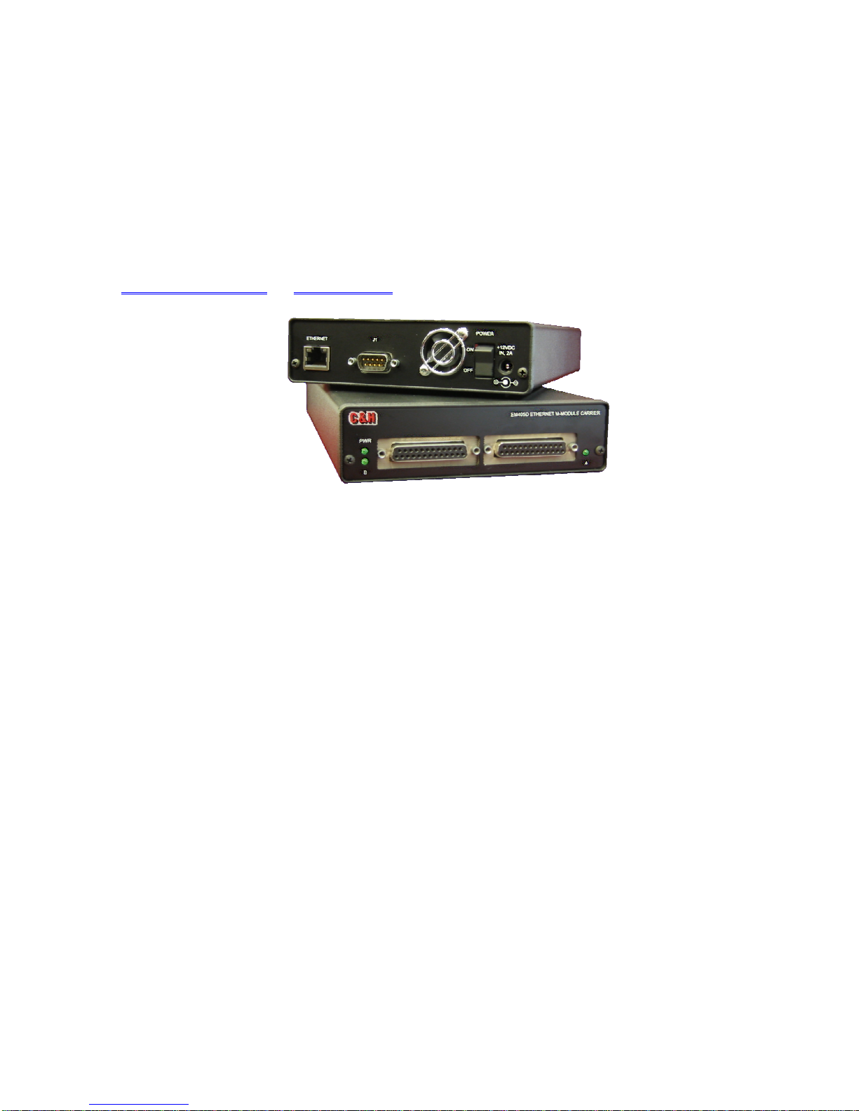
1.0 GENERAL DESCRIPTION
The EM405D Ethernet M-Module carrier provides complete Ethernet connectivity to up to two
industry standard single-wide or one double-wide M or MA modules. The carrier provides full
access to the M/MA module I/O space via the standard TCP/IP networking protocol. M-module
triggers are also fully supported allowing them to be connected externally to a 9-pin DSUB
connector or to an adjacent M-module. A simple command structure eases software integration
and allows reset, identification, control, and configuration of the carrier and M-modules. For a
complete list of M-modules compatible with the EM405D carrier, visit the mezzanine section of
www.mezzanines.org, or www.vita.com.
Figure 1. EM405D Ethernet M-Module Carrier
1.1 PURPOSE OF EQUIPMENT
The EM405 easily interfaces a VITA 12-199x standard M/MA Module to a typical Ethernet
network. The carrier allows the numerous functions available in the M-Module mezzanine
format to be remotely located near the unit-under-test, easing many system integration issues.
Over 100 M/MA modules are available from numerous manufacturers.
1.2 FEATURES AND SPECIFICATIONS
1.2.1 Key Features
Supports two ANSI/VITA 12-1996 compliant single-wide M or MA-modules or one
double-wide module
Ethernet 10Base-T, 100Base-TX (Auto-Sensing) or Wi-Fi 802.11b
Rugged steel/aluminum enclosure (5.6"W 8.5"D 1.5"H)
+12V power input through standard 2.5mm jack or 9-pin DSUB
Variable speed forced air cooling with software temperature status
D16 M-module accesses supported
Flexible block access command provides rapid sequential and FIFO data accesses
External trigger input/output and inter-module triggers supported
Isolated and filtered +5V, +12V, and -12V supplies for each M-module
Interactive Mezzanine Control (IMC) software available
1
Page 8

1.2.2 Specifications
MAXIMUM RATINGS
Parameter Condition Rating Units
Operating Temperature 0 to +60
Non-Operating Temperature -40 to +75
Humidity non-condensing 5 to 95 %
Input DC Power Level 12.6 V max.
Power Consumption Support for two M-modules at full power 30 Watts
External Trigger Input Power Off
CHARACTERISTICS
Limit
Parameter Conditions Min Typ. Max Units
Data Transfers
Throughput Wired Ethernet – block read
Input Power Supply
Level DC 11.4 12.0 12.6 V
Current for full M-module support 2.5 A
Ripple/noise 20MHz bandwidth -1.5 +1.5 %
Power Consumption
Ca rrier -0001 wired Ethernet
M-modules (each position) +5V
Triggers
Output Level into a high impedance load 3.8 5.0 5.4 V
Output Impedance 50
Input Level TLVL = 0 4
Input Impedance TIMP = 0 4
External Trigger Delay External connector to M-module
Cooling
Temperature Rise 20 °C
Temperature Accuracy -2 +2 °C
Notes:
1. 12-24ms latency occurs on each command issued. The effect of this latency is reduced by transferring
large amounts of data with a single block read command. Maximum read throughput is achieved by
reading >64K bytes of data from a FIFO type register on an M-module using the Block Read
command. Host software may vary and can limit the maximum throughput.
2. The maximum number of bytes that can be written in a single block write command is 1024.
3. Ethernet is a non-deterministic communications interface. Realized throughput may be significantly
degraded by network activity or other factors that may affect network performance.
4. TLVL and TIMP refer to register bits in the Reset & Trigger Control register. Refer to section 4.3.5.
Power On
1, 3
Wired Ethernet – block write
Wireless Ethernet – block read
Wireless Ethernet – block write
-0002 wireless Ethernet
+12V
-12V
TLVL = 1
TIMP = 1
M-module to external connector
M-module to M-module
2, 3
C
C
± 40
± 36
1, 3
2, 3
90K
460
500
100K
470
510
1.0
2.5
1.4
50
30
30
30
40K
23K
14K
550
590
200
200
V
40
40
40
V
V
bytes/sec
bytes/sec
bytes/sec
bytes/sec
mA
mA
A
mA
mA
V
ns
ns
ns
2
Page 9

1.3 Electrical
The EM405D only requires a +12V DC power input. The +12V input is internally converted to
the +3.3V power required by the carrier and the +5V, +12V, and -12V power required by the Mmodules. A maximum of 30 watts is required to support the carrier and two M-modules
operating at the maximum allowed power consumption. The maximum allowed power
consumption for each M-module is 1A of +5V and 200ma each of +12V and -12V. The
EM405D uses power-off resetable fuses on the incoming +12V supply. If a fault occurs, power
must be removed before the fuse will reset. The fuse is rated at 5 amps.
1.4 Mechanical
The EM405D is contained in a metal chassis with an outside dimension of 5.6 inches wide by 8.5
inches deep by 1.5 inches high. A variable speed fan provides forced air for cooling the Mmodules. The unit weighs approximately 1.7 lbs with no M-modules installed.
1.5 Environmental
The environmental specifications of the module are:
Operating Temperature: 0C to +60C*
Storage Temperature: -40C to +75C
Humidity: <95% without condensation
* The forced air cooling is designed to allow a maximum 20C temperature rise for installed M-
modules. In other words, with two M-modules operating at full dissipation, the M-modules’
temperature can only be maintained within 20C of the ambient air inlet temperature.
Installed M/MAs may differ in environmental specification. Refer to each individual M/MA’s
documentation for information.
1.6 Bus Compliance
The module complies with the ANSI/VITA 12-1996 Specification for single or double-wide MModules and the MA-Module trigger signal extension.
Addressing: A08 only (extended addressing not supported)
Data: D16 only
Interrupts: not supported
DMA: not supported
Triggers: Trig A and Trig B Input/Output
Manufacturer ID: 0FC116
Model Number: 0FDB16
3
Page 10

1.7 APPLICABLE DOCUMENTS
ANSI/VITA 12-1996 American National Standard for The Mezzanine Concept M-
Module Specification, Approved May 20, 1997, VMEbus
International Trade Association, 7825 E. Gelding Dr. Suite 104,
Scottsdale, AZ 85260-3415, E-mail: info@vita.com,
www.vita.com
IEEE-802.3 (ANSI 8802.3), Ethernet Network Standard
IEEE-802.11b, Wireless Ethernet Standard
4
Page 11
2.0 INSTALLATION
M/MA-Module
Carrier
A B C
2.1 UNPACKING AND INSPECTION
Verify that there has been no damage to the shipping container. If damage exists then the
container should be retained, as it will provide evidence of carrier caused problems. Such
problems should be reported to the carrier immediately as well as to C&H. If there is no damage
to the shipping container, carefully remove the instrument from its box and inspect for any signs
of physical damage. If damage exists, report immediately to C&H.
2.2 HANDLING PRECAUTIONS
The components used in the EM405D are static sensitive. Damage may occur if proper static
precautions are not taken. Installation of M-modules should only be done at a properly grounded
static free workstation.
CAUTION: Read the entire User's Manual before proceeding with the
installation and application of power.
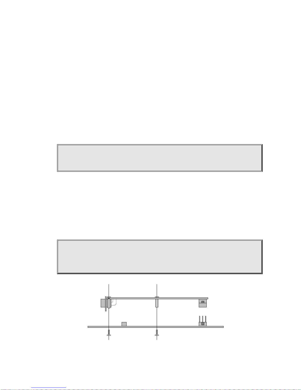
2.3 INSTALLATION OF M-MODULES
To install modules, first remove power from the carrier. Remove the front panel cover by
removing the two screws located at the sides of the panel. Do not remove the screws located on
the bottom of the enclosure. Slide the PCB out of enclosure. Install M-modules by firmly
pressing the connector on the M-module together with the connector on the carrier as shown in
Figure 2. Secure the module through the holes in the PCB using screws provided with the Mmodule.
WARNING: The EM405D supports M-modules that use two or three row
interface connectors. When using M-modules with only two
rows, row C of connector (rear row) is left unconnected.
Figure 2. M-module Installation
5
Page 12
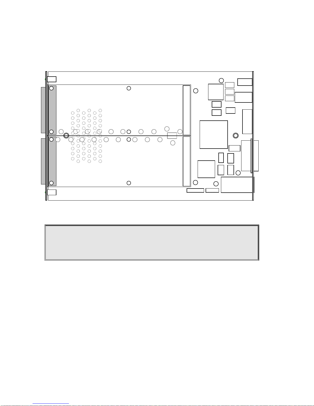
There are two M-module mounting locations on the EM405D. Single-wide M-modules may be
TMP
CPLD
PWR
CNV
uC
CPLD
DSUB
CAP
CAP
CAP
ETHERNET
uC
OSC
BUF
BUF
BUF
SIG
FUSE
FUSE
LED
POWER
FAN
SWITCH
MODULE A
MODULE B
installed in either or both of the positions. A double-wide M-module will occupy both positions.
The EM405D configuration is illustrated in Figure 3.
Figure 3. M/MA Configuration Diagram
CAUTION: M-module connectors are NOT keyed. Use extra caution to
avoid misalignment. Applying power to a misaligned module
can damage the M-module and carrier.
Re-assemble the EM405D by first sliding the carrier into the enclosure. Be careful to align the
edges of the carrier with the guide rails of the enclosure. Improper alignment will cause the back
panel component to not align with the back panel cutouts. Slide the carrier all the way into the
enclosure and re-affix the front panel using the two screw holes located at the sides of the panels.
6
Page 13
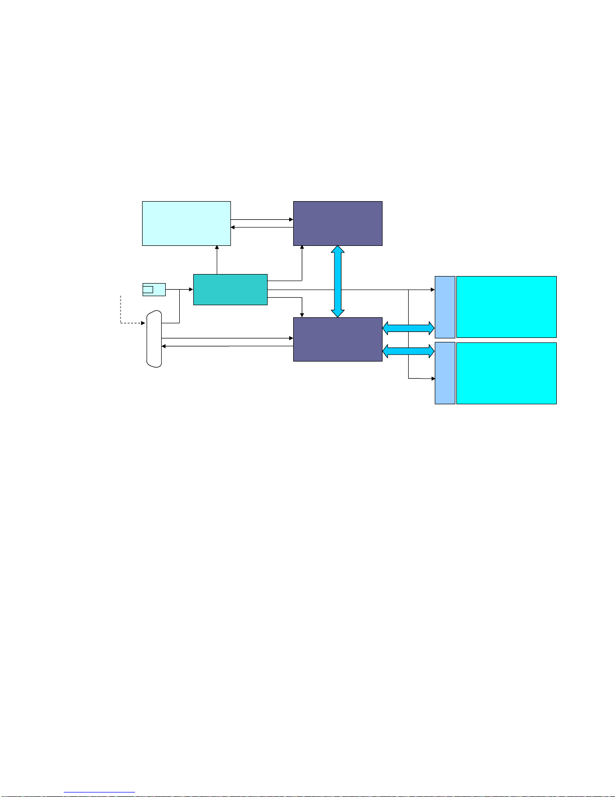
3.0 FUNCTIONAL DESCRIPTION
ETHERNET
MICRO
M-MODULE
INTERFACE
POWER
CONVERSION
POSITION A
POSITION B
+12VDC IN
M-MODULE A
M-MODULE B
TRIGGERS
OR
HERE
TRG IN
TRG OUT
10/100 BASE-T
OR WI-FI
9-PIN DSUB
3.1 GENERAL
The EM405D provides a mechanical and electrical interface between an Ethernet bus and up to
two M-modules. It utilizes an embedded microcontroller to provide buffering and command
translation between the Ethernet interface and the M-modules. A simplified functional block
diagram is shown in Figure 4.
Figure 4. Functional Block Diagram
3.1.1 Embedded Controller
The embedded controller is implemented using a high-performance microcontroller. The
microcontroller executes system firmware that controls the translation between Ethernet and the
M-module interface. The s ystem firmware implements a s imple command protocol that allows
access to the M-modules I/O space, trigger mapping and carrier information a nd status. It also
provides data buffering and fan control.
3.1.2 Ethernet Interface
The Ethernet interface provides the physical and logical connection to the EM405D allowing
remote control of the M-modules. The EM405D is available with either wired 10/100 Base-T
Ethernet or wireless Ethernet (Wi-Fi). The interface supports the TPC/IP protocol for control of
the M-modules. It also supports DHCP, AutoIP, Telnet, HTTP and other standard protocols for
device configuration and management.
7
Page 14
3.1.3 M-module Interface
ETHERNET
10/100 BASE-T
+12VDC
IN
J1
POWER
ON
OFF
The M-module interface provides the mechanism for the microcontroller to access the Mmodules. It is implemented using programmable logic that emulates a bridge between the
microcontroller and the M-module bus. The logic also provides trigger configuration and
control.
3.1.4 Power Conversion
The +12V input power is converted to the +3.3V power required by the carrier and the +5V,
+12V, and -12V power required by the M-modules. The input p ower can be supplied through
the 2.5mm power jack connector or through pins on the 9-pin DSUB connector.
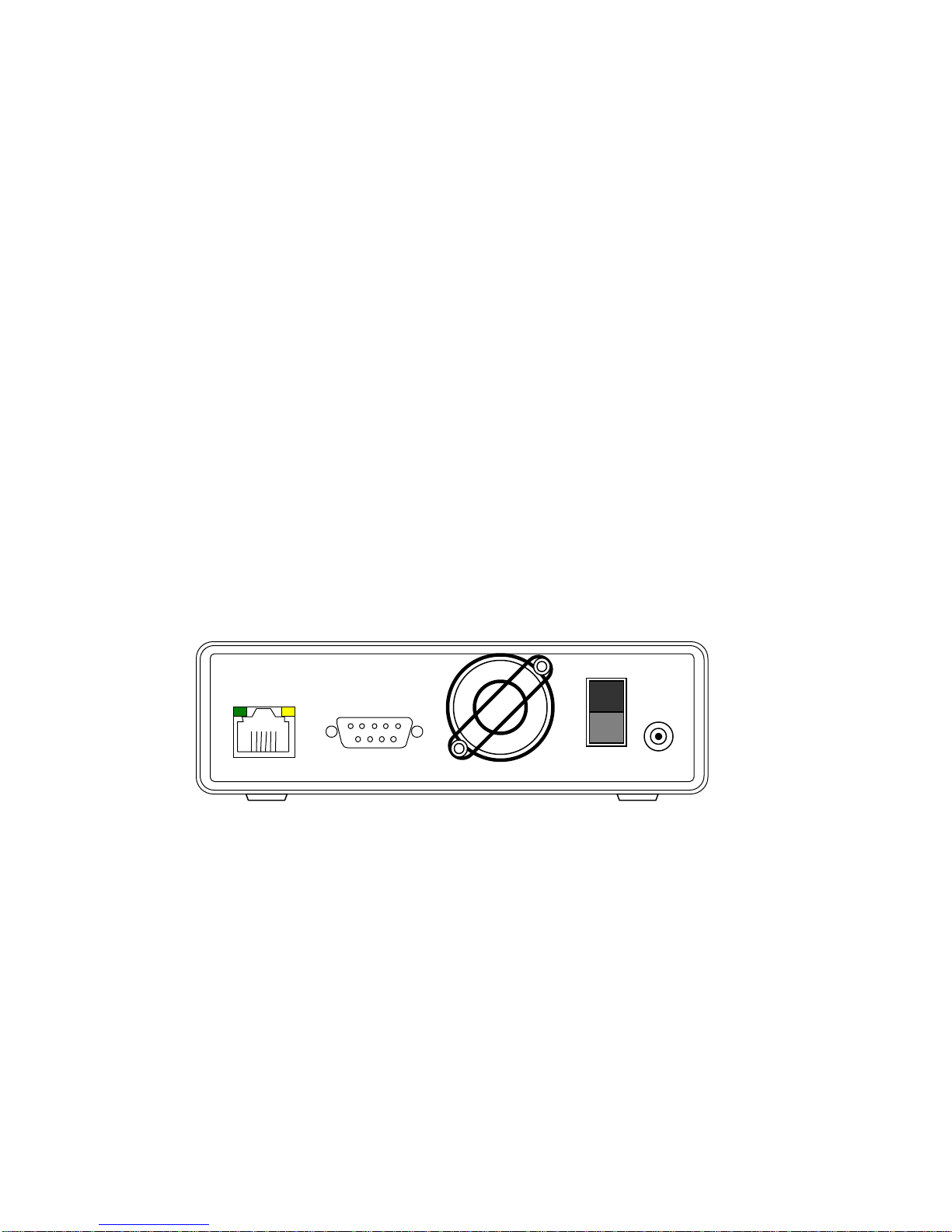
3.2 REAR PANEL
The rear panel of the EM405D contains a +12V power input connection, an Ethernet connection
or wireless antenna and a 9-pin DSUB connector that provides connection to M-module trigger
lines and an alternate power input connection. Also found on the rear panel are the fan and an
On/Off switch. Figure 5 shows the rear panel of the module. Refer to Appendix A for pin-out
details of the 9-pin DSUB connector.
Figure 5. Rear Panel
8
Page 15
3.3 FRONT PANEL
B
A
EM405D ETHERNET M-MODULE CARRIER
PWR
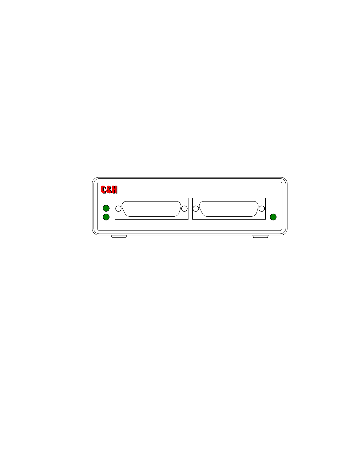
The front panel of the EM405D contains two openings for access to the M-modules’ front panel
connections and three LED indicators as shown in Figure 6. As mandated by the M-module
specification, each M-module should provide a front panel connector c ontaining the M-module
I/O signals. The two openings on the EM405D’s front panel provide access to these connectors.
The functions of the three front-panel LED indicators are:
PWR: indicates that power is supplied to the module and that the power switch is ON. The units
should be operating normally.
A, B: indicates that M-module A or B is currently being accessed. The LED will illuminate
temporarily each time the module is accessed by the host software.
Figure 6. Front Panel
9
Page 16

10
Page 17

4.0 OPERATING INSTRUCTIONS
4.1 GENERAL
The EM405D is controlled through the Ethernet interface using the TCP/IP protocol to carry a
simple command structure to the module. The carrier contains a set of software controlled
registers that allow the user to request status from the carrier, identify the carrier, and configure
the carrier. All other M/MA controls are dependent on the specific M-module(s) that reside on
the carrier.
4.2 CONFIGURING THE ETHERNET INTERFACE
The Ethernet interface must be properly configured to work on the user’s network. The
flexibility of the EM405D’s Ethernet interface allows it to be used in a large number of possible
network configurations. The unit is delivered with a default configuration that may or may not
be appropriate for the user’s network. It is up to the user and the user’s network administrator to
use the information provided throughout this section to determine what configuration is best for
the given network.
4.2.1 IP Address
The EM405D must have a unique IP address before it can communicate on a network. There are
several options for assigning an IP address to the unit. The option to choose is dependant upon
the type of network for which the EM405D is being configured.
DHCP:
The Dynamic Host Control Protocol (DHCP) allows the module to dynamically retrieve
an IP address from a DHCP server at power-up. If DHCP is used, the EM405D may have a
different IP address assigned each time it is powered on or connected to the network. For the
wired EM405D, DHCP is automatically e nabled if the IP address is set to 0.0.0.0. For the
wireless EM405D, DHCP is a separate setting. DHCP enabled is the default setting.
AutoIP: The AutoIP protocol allows the module to automatically assign itself an IP address on
networks that do not have a DHCP server. If a DHCP server is not found, the EM405D will
select an IP address from t he AutoIP reserved range (168.254.0.1 to 168.254.255.1). The unit
will then send out an address resolution (ARP) request on the network to determine if the chosen
address is already in use. If another device is using the selected IP address then the EM405D
will select another address from the range and repeat the address resolution request. This
continues unit the device finds an IP address that is not in use. For the wired EM405D, manually
setting the IP address to 0.0.0.0 enables AutoIP as well as DHCP and manually setting the IP
address to 0.0.1.0 will disable AutoIP but keep DHCP enabled. For the wireless EM405D both
AutoIP and DHCP have separate enable/disable settings. AutoIP enabled is the default setting.
Static:
For the wired EM405D, manually setting the IP address to something other than 0.0.0.0
will configure the EM405D to use the IP address specified. For the wireless EM405D DHCP
must be disabled and the IP address must be manually set. The configured IP address will
remain static even after power is removed from the module. For proper operation, the IP address
must be chosen according to the network the module is being connected to.
11
Page 18

RECOMMENDATION
The EM405D is an embedded device without an input device or display
that can be used to determine the current configuration of the device. This
can cause difficulties in determining at what IP address to access the
module. For this reason, it is highly recommended, but not required, that
the EM405D be configured to use a static IP address.
4.2.2 Subnet Mask
The subnet mask defines the number of bits that are taken from the IP address to refer to the
given network subsection. The subnet mask allows Ethernet based networks to be separated into
various subnets. The EM405D should be in the same subnet as the controlling PC.
The default subnet mask is: 255.255.255.0
4.2.3 Gateway
The gateway address allows the EM405D to communicate with other network segments. If
communication outside of the given network segment is necessary, the gateway address should
be set to the IP address of the router connecting the local network segment to the outside world.
The gateway address, if needed, must be within the local network.
The default gateway address is: 0.0.0.0
4.2.4 Port Numbers
Every TCP connection to the device is defined by a destination IP address and a port number.
The port number must be known by the software to communicate with the module. The port
number is configurable but it is rarely, if ever, necessary to change it from its default setting.
Port 9999 is reserved for Telnet access to the EM405D’s configuration utility.
The default port number for standard module access is: 10001
4.2.5 Wireless Settings
Wireless EM405D’s have other settings that must be configured for the carrier to work on a
wireless network.
Network Mode:
A wireless network can operate in one of two modes, infrastructure or ad-hoc.
In infrastructure mode, all w ireless network traffic passes through an access point. An access
point can be a bridge, a router, or a combination bridge + router device. The access point may
handle data encryption, bridging to wired networks, assigning IP addresses via DHCP, or a host
12
Page 19

of other tasks. In ad-hoc mode, wireless devices may communicate directly with each other and
an access point is not needed. In this case, all devices on the network must be configured to use
ad-hoc mode. The default network mode is: infrastructure.
SSID:
The Set Service Identifier (SSID) is a name given to a wireless access point to identify
the access point on a wireless network. Most access points can be configured to periodically
broadcast the SSID or to keep it private. Wireless devices can query the network for known
SSID and thus communicate with access points that do not broadcast it. The EM405D can be
configured to communicate with any available SSID or to query for a specific SSID and use the
owning access point if found. The default setting is to use any available SID.
Channel: The 802.11b specification defines a total of 14 frequency channels that can be used for
wireless communication. However, not all channels may be available for use. For example, the
FCC only allows for the use of channels 1 through 11 in the US; whereas most of Europe can use
channels 1 through 13. Other countries or locations may differ. All wireless communication is
done over a common channel. Another consideration in regards to channels is interference.
Interference can occur between access points or may be caused by other equipment such as
microwave ovens and cordless phones. The EM405D can be set to auto-scan mode in which the
device searches for the best wireless channel or it can be configured to use a specific channel.
The default setting is: Auto-Scan.
Country: Some countries restrict certain channel ranges and other transmission properties. The
EM405D should be configured for the country in which the device is being used. The default
setting is: USA.
Security Settings:
The EM405D supports WEP and WPA security protocols. WEP is an
encryption protocol used for secure data transfers. WPA is an authentication protocol used to
authenticate and associate a device and a wireless access point. WPA is not available in ah-hoc
mode. The security settings must be set according to the wireless network being connected to.
The default settings are: WEP disabled and WPA disabled.
4.2.6 Performing the Co nfiguration – Wired Ethernet
There are two ways to configure the wired version of the EM405D: a web-based interface and a
Telnet interface. Both ways work equally as well and the choice of which to use is based solely
on the user’s preferences. In either case, the IP address of the module must be known to perform
the configurations. If the IP address of the module is not known, one can be assigned to the
module as discussed in section 4.2.6.3.
13
Page 20

4.2.6.1 Wed-based Configuration
To use the wed-based interface to configure the wired EM405D, open a Java enabled web
browser and enter the device’s IP address as the web address to open. This will download and
run a Java applet from the device allowing the user to make changes to the devices configuration.
Navigate through the pages of the web interface making the necessary changes to the
configuration. When finished, click on the “Update Settings” button to apply the changes.
Note: If the web page does not display or operate correctly, there may be some incompatibilities
between the Java applet and the Java run-time environment on the PC. This is especially
true for users using Microsoft Internet Explorer and the Microsoft Java Virtual Machine.
It is recommended that the user download the latest Java runtime environment from
www.java.com
and disable the Microsoft Virtual Machine. The java applet served by the
wired EM405D is compatible with Java 1.3.1x or higher.
4.2.6.2 Telnet Configuration
To use the telnet interface, open a telnet session to port 9999 at the device’s IP address. In
Windows, this can b e done by opening a command prompt w indow or going to Run under the
Windows Start menu and in both cases typing the following, where x.x.x.x is the IP address:
telnet x.x.x.x 9999
PC’s running environments other than Windows may require a different instruction but the
concept remains the same. Once a telnet session is opened, the screen will display the
configuration utility. Navigate through the various menu items and follow the instructions to
configure the module. The configurations are not applied until the telnet session is exited with
the Save and Exit menu item.
4.2.6.3 Configuring a Device with an Unknown IP address
To configure the device through either the web-based interface or the telnet interface, the
EM405D must be connected to a network and have a valid IP address known to the user. This
creates an obvious dilemma. How do you configure a device via the network if it is not
configured for the network? The EM405D provides a method to overcome this dilemma using a
process sometimes referred to as address “gleaning.” This method uses the Address Resolution
Protocol (ARP) and telnet to assign a temporary IP address to the device. This temporary
address can then be used to connect to the web-based interface or the telnet interface to configure
the device for the network. To assign a temporary IP address to a device using this method:
1) Locate the device’s hardware (MAC) address and write it down. The address is
displayed on a label inside the EM405D’s cover. View the label by removing the two
screws at the front of the module, removing the front panel, then sliding the top cover of
the enclosure forward, exposing the rear section of the PCB. The MAC address can be
found on the device that the Ethernet cable physically plugs into. It is a six part number
14
Page 21

always starting with 00-20-4A identifying the manufacturer of the device. The last three
parts of the number are unique to each unit.
Example: 00-20-4A-11-68-4C
2) Create an entry in the host computer’s ARP table using the intended temporary IP address
and the hardware address of the EM405D found in step 1. To perform this action on a
Windows-based host, open the command prompt and type (the IP address can be any
available address on your network and xx-xx-xx is the last three numbers in the unit’s
MAC address):
arp –s 192.168.1.7 00-20-4a-xx-xx-xx
View the ARP table to verify that the entry was successful by typing the following:
arp –a
The ARP commands might be slightly different on non Windows based hosts.
Note: On a Windows 95 machine, the ARP command will not work unless at least one IP
address is in the ARP table. To view the ARP table, type: arp –a. If no IP addresses
are found in the table, you must ping an existing IP address on the network. If the ping is
successful, the IP address should be automatically added to the ARP table.
3) Open a Telnet connection to port 1 of the intended temporary IP address. To perform this
action type the following at the command prompt:
telnet 192.168.1.7 1
The connection will fail but will cause the EM05D to temporarily change its IP address to
the one specified.
4) Use the Telnet interface or the wed-based interface to open a session to the module using
the new temporary IP address. At this point the IP address can be configured to a more
permanent setting. The module will retain the temporary IP address until a new
configuration is applied or the module is powered-off.
4.2.7 Performing the Configuration – Wireless Ethernet (Wi-Fi)
The wireless version of the EM405D provides a web-based interface to perform network and
device configuration. A Telnet interface is not supported. To use the web-based interface, the
user must know the carrier’s IP address and the user must be able to connect to the module via a
wireless access point, router, or another wireless device capable of communicating directly with
other wireless devices (ad-hoc). If the EM405D’s configuration is not known, it can be reset to
known defaults as described in section 4.2.7.2.
15
Page 22

4.2.7.1 Wed-based Configuration
To use the wed-based interface to configure the wireless EM405D, open a web browser and enter
the device’s IP address as the web address to open. This will launch the main web page of the
configuration utility. Navigate through the pages of the web interface making the necessary
changes to the configuration. When finished making changes in any given section, click on that
pages “Apply” button to apply the changes. Some changes may require that the wireless
Ethernet interface be rebooted, in which case the user will need to re-connect to the device.
4.2.7.2 Restoring Factory Defaults
Similar to the wired version, the wireless version of the EM405D has a dilemma in which the
carrier must be connected to a network in order to configure its network properties. The
dilemma is made worse in the wireless version by the fact that there is no physical connection to
the device and there are additional configuration settings that must be known in order to connect
to the device, such as the network mode, security settings (WEP, WPA), channel setting, and the
SSID. If the EM405D configuration is not known and thus the user cannot connect to the carrier,
it is possible to reset the configuration settings to known defaults using a small push-button
switch found on the inside the EM405D enclosure.
CAUTION: The following procedure requires opening the EM405D
enclosure and applying power while the PCB is exposed. Use
extreme caution when attempting to perform the procedure as
to not damage the carrier or any of its components.
To restore the factory defaults:
1) Turn power Off.
2) Remove the front panel cover by removing the two screws located at the sides of the
panel. Do not remove the screws located on the bottom of the enclosure.
3) Slide the top cover of the enclosure forward exposing the rear portion of the PCB.
4) Locate the tiny push button switch near the Ethernet device (bottom right hand corner of
the PCB when the carrier is oriented as shown in Figure 3).
5) Using a finger or a tool, such as the eraser end of a pencil, press and hold the button.
6) While holding the button down, turn the device On.
7) Continue holding the button pressed until the amber colored LED on the back of the
Ethernet device flashes a 1-5-1 sequence.
8) Once the 1-5-1 sequence is complete, the device has been reset to its factory defaults and
the user may release the button.
9) Re-assemble the EM405D by sliding the top cover back into place and re-installing the
front panel.
16
Page 23

The defaults that are restored using the above procedure are those set by the manufacturer of
the Ethernet device and not by C&H Technologies, Inc. The default settings of the carrier as
received from the factory at C&H are different in several key areas. The user must manually
return these settings to the default as set by C&H in order for the carrier to operate properly.
Refer to APPENDIX C or details on the factory default settings as received from C&H
Technologies, Inc.
4.3 COMMUNICATING WITH THE CARRIER AND M-MODULES
The EM405D uses a simple binary command structure to communicate with the host s oftware.
The commands allow the user to either write or read registers residing on the EM405D or on
each M-module. By writing regis ters residing on the EM405D, the user can identify the module,
perform device configuration, and receive status. The registers residing on each M-module are
specific to the particular M-module. Refer to the M-module’s documentation for register details.
Each command consists of a command-id byte, a module number on which the command is to be
executed and parameters, if required. The commands are listed in Table I. Details of each
command are found throughout the rest of this section.
Table I. Command Summary
Binary
Command-id Function
0x20 Write Data
0x30 Read Data
0x40 Block Write
0x50 Block Read
4.3.1 Error Handling
Each command will return a status code as the last byte returned. This status code will indicate
whether the command completed successfully or whether an error occurred while the EM405D
was performing the command. Table II shows a list of potential status codes that may be
returned.
Table II. Status Code (SC)
Value
0x00 Successful
0x01 Invalid Command
0x02 Invalid Parameter
0x03 Module did not respond*
* Note: Applies to M-module requests only.
Meaning
17
Page 24

Successful (0x00): The command completed successfully without error.
Invalid Command
(0x01): The first byte received was not a valid command-id value from the
list in Table I.
Invalid Parameter (0x02): The EM405D received a valid command however the command could
not be completed because one of the command parameters was invalid or out of range. Refer to
the description of each individual command for parameter details.
Module D id Not Respond (0x03): The EM405D received a valid command with valid
parameters; however, the specified module did not respond to the access. This error code applies
to M-module accesses only. The error code could result from the specified M-module being
absent, the specified address being outside the range of addresses supported by the particular Mmodule, or more serious hardware problems with the M-module itself.
Once any of the above status codes are returned, the EM405D will set the Reset Error (RERR)
status bit in t he EM405D Reset Error and Manufacturer ID register (refer to section 4.3.5 for
details on this register) and cease responding to further commands except the Read Data and
Write Data commands to the Reset Error and Manufacturer ID register. To recover from this
condition, the user must clear the RERR bit by writing a ‘1’ to that bit location in the Reset Error
and Manufacturer ID register.
This functionality is implemented so that when the EM405D recognizes an error at the beginning
of a command, it can search the buffer for the next command without having to send a status
code response for each byte remaining in the buffer. For example, assume this functionality
didn’t exist and the user wanted to perform a block write with a 1024 byte block. The full
command for this action, including data, requires 1033 bytes to be placed into the EM405D’s
buffer. If the third byte in the command is an invalid parameter, the EM405D would return an
Invalid Parameter (0x02) status code followed by one thousand and thirty Invalid Command
(0x01) status codes, one for each byte in the buffer after the invalid parameter. By implementing
this functionality, the EM405D will ignore the one thousand and thirty bytes and any following
bytes in the buffer unless the command is a Read Data or Write Data of the Reset Error and
Manufacturer ID register or until the RERR bit is reset to ‘0’.
The software must be written such that it checks for error conditions and performs the
appropriate action to reset the RERR bit. In most cases error conditions are generated by
errors in the software source code, therefore, once the software has been debugged and
verified, error codes will rarely, if ever be received.
18
Page 25

4.3.2 Write Data command
The Write Data command writes data to an EM405D control register or to a register residing on
an M-module. The command consists of seven bytes including the command-id, the module to
which the data should be written, an address space selector, the access width, the address, and
two data bytes. The return value consists of a single status byte.
Command Syntax:
0x20 md as ws ad dh dl
Return:
SC
where
md = module (0 = EM405D control, 1 = M-module A, 2 = M-module B)
as = address space (0 = I/O, 1 = future use)
ws = word size (2 = 16-bit word, other values for future use)
ad = address (0 to FF)
dh = data (MSB)
dl = data (LSB)
SC = Status Code
Example (values shown hex):
To write the data value 0x1234 to M-module A, send the following command:
Command: cd md as ws ad dh dl
Send: 20 01 00 02 06 12 34
Receive: 00 (if successful)
4.3.3 Read Data command
The Read Data command reads data from an EM405D control/status register or from a register
residing on an M-module. The command consists of five bytes including the command-id, the
module from which the data should be read, as address space selector, the access width and the
address from which to read. The return value consists of two data bytes followed by a single
status byte.
Command Syntax:
0x30 md as ws ad
Return:
dh dl SC
where
md = module (0 = EM405D control, 1 = M-module A, 2 = M-module B)
as = address space (0 = I/O, 1 = future use)
ws = word size (2 = 16-bit word, other values for future use)
ad = address (0 to FF)
dh = data (MSB)
dl = data (LSB)
SC = Status Code
19
Page 26

Example (values shown hex):
To read the Device Identification Register on the EM405D, send the following command:
Command: cd md as ws ad
Send: 30 00 00 02 02
Receive: 0F DB 00 (if successful)
4.3.4 Block Access
The EM405D provides a flexible block access feature that can be used to significantly improve
data throughput. Both a block read and a block write command is implemented. The flexibility
of the bock access feature is in the command protocol. The protocol allows the user to specify
four parameters in addition to the standard parameters also found in the single data read and
write commands: starting address, block size, number of blocks, and address increment.
The EM405D firmware will execute the command by reading or writing a block of data the size
of the block size parameter, starting from the starting address and ending at:
starting address + (block size * word size)
The firmware will then repeat this process N number of times depending on the number of blocks
parameter. If the address increment parameter is not equal to 0, the firmware will increment the
starting address by the specified amount after each read or write of a single block.
The M-module I/O space is a maximum of 256 bytes. Care must be taken when performing a
block access that an address greater than 0xFF is never accessed. Otherwise, an error will occur
and the block access will terminate immediately.
The following examples further illustrate the block access feature.
Example 1:
starting address = 0x4
block size = 32
number of blocks = 1
address increment = don’t care
Read a single block of 32 words (64 bytes) starting at address 0x4.
Example 2: Read 32 words (64 bytes) from a FIFO at address 0x8.
starting address = 0x8
block size = 1
number of blocks = 32
address increment = 0
Example 3: Read 32 words from two FIFOs one at address 0x8 and another at address 0xA
starting address = 0x8
block size = 2
number of blocks = 32
address increment = 0
20
Page 27

Example 4: Read 32 words starting at address 0x0 followed by 32 words starting at address 0x80
starting address = 0x0
block size = 32
number of blocks = 2
address increment = 128
4.3.4.1 Block Write command
The Block Write command writes a block of data to an M-module. A maximum of 1024 bytes
can be written in a single command. The number of bytes written in any given command is
equal to:
number of bytes = number of blocks * block size * word size
The block write command consists of nine command bytes and any number (up to 1024) of data
bytes. The return value is a single status byte indicating the success of the command.
Command Syntax:
0x40 md as ws ad ai nh nl bs d1 d0 …
Return:
SC
where
md = module (0 = invalid, 1 = M-module A, 2 = M-module B)
as = address space (0 = I/O, 1 = future use)
ws = word size (2 = 16-bit word, other values for future use)
ad = starting address (0 to FF)
ai = address increment (number to increment address by after each write)
nh = number of blocks to read (upper 4 bits)
nl = number of blocks to read (lower 8 bits)
bs = block size in words (i.e., number of words
d1 = data (MSB)
d0 = data (LSB)
… = the number of data bytes = ws bs nb
SC = Status Code
Example (values shown hex):
To write the data values 0x1234, 0x5678, 0x9ABC to M-module A starting at I/O Register 4, send the
following command:
Command: cd md as ws ad ai nh nl bs dh1 dl1 dh2 dl2 dh3 dl3
Send: 40 01 00 02 04 02 00 03 01 12 34 56 78 9A BC
Receive: 00 (if successful)
per block)
21
Page 28

4.3.4.2 Block Read command
The Block Read command reads a block of data from an M-module. Unlike the block write
command, block read does not have a restriction on the number of bytes that can be read with a
single command. The number of bytes read in any given command is equal to:
number of bytes = number of blocks * block size * word size
The block read command consists of nine command bytes. The return value is any number of
data bytes followed by a single status byte indicating the success of the command.
Command Syntax:
0x50 md as ws ad ai nh nl bs
Return:
d1 d0 ... SC
where
md = module (0 = invalid, 1 = M-module A, 2 = M-module B)
as = address space (0 = I/O, 1 = future use)
ws = word size (2 = 16-bit word, other values for future use)
ad = starting address (0 to FF)
ai = address increment (number to increment address by after each write)
nh = number of blocks to read (upper 4 bits)
nl = number of blocks to read (lower 8 bits)
bs = block size in words (i.e., number of words
d1 = data (MSB)
d0 = data (LSB)
… = the number of data bytes = ws bs number of blocks (nh:nl)
SC = Status Code
Example (values shown hex):
To read three data values from a 32-bit FIFO located at I/O Register 6 and 8 on M-module B, send
the following command:
Command: cd md as ws ad ai nh nl bs
Send: 50 02 00 02 06 00 00 03 02
Receive: da1 db1 dc1 dd1 da2 db2 dc2 dd2 da3 db3 dc3 dd3 00 (if successful)
where
dax = MSB of register 6
dbx = LSB of register 6
dcx = MSB of register 8
ddx = LSB of register 8
Note: x = 1 is first read, x = 2 is second read, x = 3 is third read
per block)
22
Page 29

4.3.5 EM405D Configuration/Status Registers
The EM405D contains a set of registers that are used to identify the carrier, configure the carrier,
and retrieve status from the carrier. These registers are independent of the M-modules r esiding
on the board. Table III summarizes the register map. Bit level details of each register can be
found in Figure 7. These registers are accessed using the Read Data and Write Data commands
with the module field of the command set to ‘0’.
Table III. Register Summary
Offset
0x00 Reset Error & Manufacturer Identification
0x02 Device Identification
0x04 Hardware Version
0x06 Firmware Version
0x08 Reset & Trigger Control
0x0A Fan Control & Temperature Status
Register
Reset Error & Manufacturer Identification
(0x00): A read of this register will return the 12-bit
manufacturer ID value of the EM405D and the reset error bit. The manufacturer ID field is readonly. Writing a ‘1’ to the reset error bit will clear the error condition. Refer to section 4.3.1 for
details on error handling.
Device Identification (0x02): This read-only register returns the device ID value of the EM405D
and a bit indicating whether the EM405D is a wired or wireless (Wi-Fi) version.
Hardware Version
(0x04): This read-only register returns the hardware version number of the
EM405D being accessed.
Firmware Version (0x06): This read-only register returns the firmware version number of the
EM405D being accessed.
Reset & Trigger Control
(0x08): This read/write register can be used to reset the M-modules
residing on the EM405D and to control the triggers. An independent reset bit is available for
each module as well as numerous bits that allow the user to configure the external trigger lines
and to map each M-module trigger.
Fan Control & Temperature Status (0x0A): A read of this register will return a value
representative of the current temperature inside the EM405D casing and will return the current
setting of the fan c ontrol bit. The t emperature field of this register is read only. By writing to
the fan control bit, the user can select whether the fan is set to full-on or variable speed.
23
Page 30

Reg. 00
Byte 1 0
Bit 15 14 13 12 11 10 9 8 7 6 5 4 3 2 1 0
Write RERR - - - Read Only
Read RERR 0 0 0 MID
Reset Error & Manufacturer Identification
RERR Reset Error (writing a 1 clears the error condition) 1
MID Manufacturer ID (always FC116 - C&H)
Notes:
1. This bit is set if a command error occurs. If an error exists, only reads or writes to this register are
allowed. The RERR bit must be cleared by writing a 1 to this bit before normal command operation
will resume. See 4.3.1 for further details.
Reg. 02
Byte 3 2
Bit 15 14 13 12 11 10 9 8 7 6 5 4 3 2 1 0
Write - - - - Read Only
Read ETH 0 0 0 DID
Device Identification
ETH Ethernet Type (0 = wired, 1 = wireless (Wi-Fi))
DID Device ID (always FDB16 - EM405D)
Reg. 04
Byte 5 4
Bit 15 14 13 12 11 10 9 8 7 6 5 4 3 2 1 0
Write Read Only Read Only
Read HW Major HW Minor
Hardware Version
HW Major Major Version Level of EM405D Hardware
HW Minor Minor Version Level of EM405D Hardware
Reg. 06
Byte 7 6
Bit 15 14 13 12 11 10 9 8 7 6 5 4 3 2 1 0
Write Read Only Read Only
Read FW Major FW Minor
Firmware Version
FW Major Major Version Level of EM405D Firmware
FW Minor Minor Version Level of EM405D Firmware
Figure 7. EM405D Registers
24
Page 31

Reg. 08
Byte 9 8
Bit 15 14 13 12 11 10 9 8 7 6 5 4 3 2 1 0
Write RSTB RSTA TLVL TIMP BTBD BTBM BTAD BTAM ATBD ATBM ATAD ATAM
Read RSTB RSTA TLVL TIMP BTBD BTBM BTAD BTAM ATBD ATBM ATAD ATAM
Reset & Trigger Control
RSTB Reset M-module B (0 = normal, 1 = reset) 1
RSTA Reset M-module A (0 = normal, 1 = reset) 1
TLVL External Trigger Input Threshold Level (0 = +2.5V, 1 = +1.4V)
TIMP External Trigger Input Impedance (0 = high (>100K), 1 = 50)
BTBD Module B Trigger B Direction (0 = input, 1 = output) 2
BTBM Module B Trigger B Mode
0 0 Disabled
0 1 to/from External Trigger
1 0 to/from Module A Trigger A
1 1 to/from Module A Trigger B
BTAD Module B Trigger A Direction (0 = input, 1 = output) 2
BTAM Module B Trigger A Mode
0 0 Disabled
0 1 to/from External Trigger
1 0 to/from Module A Trigger A
1 1 to/from Module A Trigger B
ATBD Module A Trigger B Direction (0 = input, 1 = output) 2
ATBM Module A Trigger B Mode
0 0 Disabled
0 1 to/from External Trigger
1 0 to/from Module B Trigger A
1 1 to/from Module B Trigger B
ATAD Module A Trigger A Direction (0 = input, 1 = output) 2
ATAM Module A Trigger A Mode
0 0 Disabled
0 1 to/from External Trigger
1 0 to/from Module B Trigger A
1 1 to/from Module B Trigger B
Notes:
1. This bit must be cleared by user software to return the M-module to normal operation. The reset bit
need only be set to a 1 for a minimum of 1s to properly reset an M-module.
2. The direction is with respect to the M-module specified. For intermodule triggers, the M-module
trigger directions must be set opposite one another for proper operation.
Reg. 0A
Byte B A
Bit 15 14 13 12 11 10 9 8 7 6 5 4 3 2 1 0
Write VARF - - - Read Only
Read VARF 0 0 0 TEMP
Fan Control & Temperature Status
VARF Variable Speed Fan (0 = variable, 1 = full ON)
TEMP Enclosure Temperature (°C = (TEMP – 281) / 4.6)
Figure 7. EM405D Registers (continued)
25
Page 32

4.4 CONTROLLING THE TRIGGERS
The carrier implements flexible trigger control capabilities providing the user with many options
for using triggers. Each M-module can support two trigger lines (labeled A & B) which can be
mapped to one of two external trigger lines (one input and one output) available on the carrier or
to the trigger lines of the adjacent M-module.
The carrier’s external trigger lines can be accessed at the 9-pin DSUB connector on the back
panel of the EM405D. Refer to Appendix A for pin-out details of the 9-pin DSUB connector.
The input trigger line has a software configurable threshold and input impedance. The input
threshold is configurable using the TLVL bit in the Reset & Trigger Control register and can be
set to either +1.4 volts or +2.5 volts. The input impedance is configurable using the TIMP bit in
the Reset & Trigger Control register and can be set to either high impedance (>100K) or 50.
The output trigger line has a set output impedance of 50and a set output drive level of +5V
(typical) into a high impedance load.
Each M-module trigger line can be configured to be either an input or an output and can be
mapped to either the external trigger lines or to one of the trigger lines on the other M-module.
Each trigger line contains two bit fields in the Reset & Trigger Control register. The xTzD bit
controls the trigger direction and the xTzM controls the trigger mapping, where x specifies the
module and z specifies the trigge r (for example ATBM is module A trigger B). If the xTzM bit
field is set to map the trigger line to the external trigger, the trigger is connected to either the
external input or the external output depending on the value of the xTzD bit. If the xTzM bit
field is set to map the trigger line to another M-module trigger line, then the two triggers must be
configured to be opposite directions. Also the second M-module trigger line must be mapped to
the first M-module trigger line. For example, if module A trigger B is to be outputted to module
B trigger A then the corresponding bit fields must be set as follows:
ATBD = output
ATBM = to/from Module B Trigger A
BTAD = input
BTAM = to/from Module A Trigger B
The following values would be invalid:
ATBD = output
ATBM = to/from Module B Trigger A
BTAD = output
BTAM = to/from Module A Trigger B
or
ATBD = output
ATBM = to/from Module B Trigger A
BTAD = input
BTAM = to/from external trigger
26
Page 33

The function of each M-module trigger line is fully dependent upon the M-module. Refer to the
particular M-module’s documentation for further details.
4.5 FAN AND TEMPERATURE CONTROL
The EM405D contains an on-board temperature sensor placed near the M-module positions. The
current temperature inside the EM405D case can be determined by reading the Fan &
Temperature Control register of the EM405D. The TEMP field inside this register represents the
current temperature as read by the temperature sensor. To translate the TEMP value in to
degrees Celsius use the following equation:
°C = (TEMP – 281) / 4.6
The temperature sensor is also read by the firmware and used to control the variable speed fan.
When the fan is set to variable, the firmware constantly monitors the temperature and speeds up
the fan as the temperature rises. The variable fan is designed to maintain a maximum 20° C rise
in temperature from the ambient inlet air. The user may select the fan to remain full on at all
times by setting the VARF bit in the Fan & temperature Control register to a ‘1’.
27
Page 34

28
Page 35

A-1
PIN DESCRIPTION
1 +12V INPUT
2 +12V INPUT
3 +12V INPUT
4 TRIGGER OUT
5 TRIGGER IN
6 GND
7 GND
8 GND
9 GND
5 4 3 2 1
9 8 7
6
APPENDIX A - CONNECTORS
Figure A-1. 9-Pin DSUB Connector
Page 36

A-2
Page 37

B-1
APPENDIX B – WIRED ETHERNET DEFAULT SETTINGS
The Ethernet interface device on the wired version of the EM405D contains many configurable
settings that allow it to be used in a large number of applications. Many of these settings must be
set to certain values in order for the EM405D to operate normally. Other settings are not
applicable to the EM405D. When the user tries to configure the network settings via the webinterface or the telnet interface, he/she will see options to change many of these settings.
Changing some of these may make the EM405D inoperable. For this reason, it is highly
recommended that the user does not change any settings other than the following:
IP Address
Subnet Mask
Gateway Address
Table B-1 lists the various settings and their default values as set my C&H during manufacturing
of the EM405D. If the carrier fails to operate, verify that these settings are set to their default
values prior to calling C&H for technical support. Settings that are emphasized in bold italics
are required settings that if changed will render the carrier inoperable.
Table B-1. Ethernet Interface Default Settings.
Server Properties
IP Address 0.0.0.0
Subnet Mask 0.0.0.0
Gateway Address 0.0.0.0
Serial Settings
Baud Rate 921600
Data bits 8
Parity None
Stop bits 1
Flow control None
UDP Datagram Mode
Datagram Mode False
Datagram Type N/A
Passive Connection
Password Required False
Port Password N/A
Accept Passive Connection Yes
Local Port** 10001
Auto Increment Source Port False
** The EM405D will operate with any port number; however, many software applications
expect the port to be set to the default as shown in this table. Changing the port number will
not render the EM405D inoperable but may render these software applications inoperable.
Page 38

B-2
Table B-1. Ethernet Interface Default Settings. (continued)
Active Connection
Active Connection None
Telnet Mod N/A
Terminal Type N/A
Remote Port N/A
Connection Response None
Modem Emulation Mode None
Use Host List N/A
Remote Host N/A
Disconnection
Disconnect with EOT N/A
Disconnect with DTRDrop False
Disable Hard Disconnect False
Inactivity Timeout 00:00
Connection
Connection LED Blink
Buffer Flushing
Flush Output Buffer
- At Time of Disconnect False
- On Passive Connection True
- On Active Connection False
Flush Input Buffer
- At Time of Disconnect False
- On Passive Connection True
- On Active Connection False
Packing
Enable Packing True
Send Trailing Bytes None
Send Frame Only False
Match Two Byte Sequence False
Idle Time Force Transmit 12ms
Match Byte 2 00
Match Byte 1 00
Device
Firmware Type N/A
Firmware Version N/A
Product Type N/A
Page 39

B-3
Table B-1. Ethernet Interface Default Settings. (continued)
Email Notification
Domain Name blank
Mail Server 0.0.0.0
Recipients (Collection)
Triggers (Collection)
Unit Name blank
Host List
Host List (Collection)
Retry Counter 3
Retry Timeout 250
OEM Configurable Pins
Pin 1 IN1
Pin 2 IN2
Pin 3 IN3
User IO ActiveLow
XPort-03
CPU Performance High
Page 40

B-4
Page 41

C-1
APPENDIX C – WIRELESS ETHERNET (Wi-Fi) DEFAULT SETTINGS
The Ethernet interface device on the Wireless version of the EM405D contains many
configurable settings that allow it to be used in a large number of applications. Many of these
settings must be set to certain values in order for the EM405D to operate normally. Other
settings are not applicable to the EM405D. When the user tries to configure the network settings
via the web-interface, he/she will see options to change many of these settings. Changing some
of these may make the EM405D inoperable. For this reason, it is highly recommended that the
user does not change any settings other than the following:
IP Address
Subnet Mask
Gateway Address
Wireless LAN Settings
Wireless Security Settings
Table C-1 lists the various settings and their default values as set my C&H during manufacturing
of the EM405D. If the carrier fails to operate, verify that these settings are set to their default
values prior to calling C&H for technical support. Settings that are emphasized in bold italics
are required settings that if changed will render the carrier inoperable.
Table C-1. Wireless Ethernet Configuration Default Settings.
Network
IP Settings
Obtain an IP address autom atically using DHCP True
Wireless LAN Settings
Connect to wireless access points (infrastructure) True
Connect to any available wireless network True
Country United States
Channel Auto-Scan
Wireless Security Settings
Enable WEP security False
Enable WPA authentication False
Network Services Settings
Enable ADDP True
- Port 2362
Enable Encrypted RealPort True
- Port 1027
Enable HTTP & HTTPS True
- HTTP Port 80
- HTTPS Port 443
Page 42

C-2
Table C-1. Wireless Ethernet Configuration Default Settings. (continued)
Enable Line Printer Daemon (LPD) True
- Port 515
Enable RealPort True
- Port 771
Enable Remote Login (rlogin) True
- Port 513
Enable Remote Shell (rsh) True
- Port 514
Enable SNMP True
- Port 161
Enable Telnet True
- Port 23
Advanced Network Settings
Enable AutoIP address assignment True
RTS Threshold 2347
Fragmentation Threshold 2346
Serial Port
Port Profile Settings
Current Port Profile TCP Sockets
TCP Server Settings
Enable Telnet access using TCP Port False
- Port N/A
Enable Raw TCP access using TCP Port True
- Port** 10001
Enable Secure Socket access using TCP Port False
- Port N/A
TCP Client Settings
Automatically establish TCP connections False
Basic Serial Settings
Description blank
Baud Rate 230400
Data Bits 8
Parity None
Stop Bits 1
Flow Control None
** The EM405D will operate with any port number; however, many software applications
expect the port to be set to the default as shown in this table. Changing the port number will
not render the EM405D inoperable but may render these software applications inoperable.
Page 43

C-3
Table C-1. Wireless Ethernet Configuration Default Settings. (continued)
Advanced Serial Settings
Enable Port Logging False
Enable RTS Toggle False
Enable RCI over Serial (DSR) False
Send Socket ID False
Send data only under any of the following conditions True
- Send when data is present on the serial line False
- Send after the following number of idle milliseconds True - 12 ms
- Send after the following number of bytes 1024
- Close connection after the following number of idle
False
seconds
- Close connection when DCD goes low False
- Close connection when DSR goes low False
GPIO
General Purpose Input/Output Pins
Pin 1 In
Pin 2 In
Pin 3 In
Pin 4 In
Pin 5 In
Alarms
Alarm Notification Settings
Enable Alarm Notifications False
Alarm Conditions
Alarm 1 …Alarm 32 False
Security
Administrator Password
Enable Password Authentication False
System
System Settings
Description blank
Contact blank
Location blank
Simple Network Management Protocol (SNMP) Settings
Enable Simple Network Management Protocol (SNMP) True
- Public community public
- Private community private
- Allow SNMP clients to set device settings through SNMP False
Enable Simple Network Management Protocol (SNMP) traps False
Page 44

C-4
Page 45

N O T E S:
Page 46

.
Page 47

READER'S COMMENT FORM
Your comments assist us in improving t he use fulness of C&H's publications; they ar e an
important part of the inputs used for revision.
C&H Technologies, Inc. may use and distribute any of the information that you supply in any
way that it believes to be appropriate without incurring any obligation whatsoever. You may, of
course, continue to use the information, which you supply.
Please refrain from using t his form for technical questions or for requests for additional
publications; this will only delay the response. Instead, please direct your technical questions to
your authorized C&H representative.
COMMENTS:
Thank you for helping C&H to deliver the best possible product. Your support is appreciated.
Sincerely,
F. R. Harrison
President and CEO
Page 48

Place
Stamp
Here
INSTRUCTIONS
In its continuing effort to improve documentation, C&H Technologies, Inc. provides this form
for use in submitting any comments or suggestions that the user may have. This form may be
detached, folded along the lines indicated, taped along the loose edge (DO NOT STAPLE), and
mailed. Please try to be as specific as possible and reference applicable sections of the manual or
drawings if appropriate. Also, indicate if you would like an acknowledgment mailed to you
stating whether or not your comments were being incorporated.
NOTE: T his form may not be used to request copies of documents or to request
waivers, deviations, or clarification of specification requirements on current
contracts. Comments submitted on this form do not constitute or imply
authorization to waive any portion of the referenced document(s) or to amend
contractual requirements.
(Fold along this line)
(Fold along this line)
______________________
______________________
______________________
C&H Technologies, Inc.
Technical Publications
445 Round Rock West Drive
Round Rock, Texas 78681-5012
 Loading...