

Page 1
Page 2

i
FOREWORD
CHTC (USA), INC.
OPERATOR’S MANUAL
for
HT45 MOTOR COACH
12851 S. Reservoir Street
Chino, CA 91710
Tel: 909-325-8588
Fax: 909-993-0838
www.chtcusa.com
Every effort has been made to ensure accuracy and quality in
publication of this document. At the time of printing, content is the most
current available.
Due to technological advancements and continuous improvement of
our products and the products of our component suppliers, CHTC
(USA), INC. reserves the right to change specifications without
notification.
PREFACE
Please allow us to express our thanks for your selecting our new HT 45
Motor Coach. We believe you will be impressed by the quality and
performance of this product.
•
Our HT 45 Motor Coach is economical, safe and comfortable. This
manual will introduce you to some important how-to about dri ving,
operating, and maintaining your new HT 45 Motor Coach. Please
read it carefully. Please operate and maintain your HT 45 Motor
Coach in accordance with this manual, which will he lp you k eep
your HT 45 Motor Coach in optimal condition and maximize its
service life.
•
If any questions, comments or concerns arise in your operation or
maintenance of your new HT 45 Motor Coach, pleas e contact our
National Service Group at 800-216-6788 or access our dedicated
support website at www.chtcusa.com.
We strive to provide
optimal customer service as well as parts availability and
maintenance support. CHTC (USA), INC. strives to continuously
improve and adapt in order to provide you with the highest
quality product, service and support.
•
Consider this manual a permanent part of this HT 45 Motor
Coach. If the HT 45 Motor Coach is sold or traded, also include
this manual to provide the next owner with important operating,
safety, and maintenance information.
Page 3

ii
FOREWORD
NOTES
Page 4

iii
TABLE OF CONTENTS
INTRODUCTION
SAFETY INSTRUCTIONS ........................................................... 1
HOW TO USE THIS MANUAL ..................................................... 2
VEHICLE IDENTIFICATION NUMBER (VIN) PLATES ............... 2
MOTOR COACH SPECIFICATIONS ........................................... 3
BODY STRUCTURE .................................................................... 3
ELECTRICAL SYST EM ............................................................... 3
ENGINE SPECIFICATION ........................................................... 4
TRANSMISSION SPECIFICATIONS ........................................... 5
SUSPENSION .............................................................................. 6
STEERING SYSYTEM ................................................................. 6
WHEELS AND TIRES .................................................................. 6
BRAKING SYSTEM ..................................................................... 6
SAFETY
OPERATOR PRECAUTIONS ...................................................... 7
PASSENGER SEATBELTS ......................................................... 8
WARNING LABELS ..................................................................... 8
ROAD SAFETY ............................................................................ 8
FIRE EXTINGUISHER ................................................................. 9
EMERGENCY EXITS ................................................................... 9
INTEGRATED BACKUP CAMERA ............................................ 10
CONTROLS
INSTRUMENT PANEL ............................................................... 11
SWITCH PANELS ...................................................................... 16
CLIMATE CONTROLLER .......................................................... 20
STEERING WHEEL AND COLUMN .......................................... 24
EXTERIOR MIRRORS SELECT/CONTROL KNOB .................. 24
PARKING BRAKE ...................................................................... 27
EMERGENCY BRAKE ............................................................... 28
DRIVER’S SEAT ........................................................................ 29
DELUXE TOUR GUIDE SEAT ................................................... 32
PASSENGER SEATS ................................................................ 33
GEAR SELECTOR ..................................................................... 34
PASSENGER INTERIOR CONTROLS ..................................... 36
OPERATING
GENERAL INSTRUCTIONS ..................................................... 37
ENGINE STARTUP ................................................................... 37
WINTER DRIVING TIPS ........................................................... 39
DPF REGENERATION .............................................................. 39
PARK REGENERATION ........................................................... 42
AUDIO/VISUAL SYSTEM.......................................................... 43
LAVATORY ............................................................................... 46
ELECTRIC DRIVER SUN SHADES .......................................... 49
ENTRANCE DOOR EMERGENCY RELEASE ......................... 49
LUGGAGE COMPARTMENT .................................................... 50
SPARE TIRE COMPARTMENT ................................................ 51
Page 5

iv
TABLE OF CONTENTS
DAILY INSPECTIONS
ENGINE OIL LEVEL ................................................................. 52
ENGINE OIL PRESSURE ........................................................ 52
DRIVE BELTS AND BELT TENSION ....................................... 52
BATTERY ................................................................................. 53
WASHER FLUID ....................................................................... 53
WINDSHIELD WIPER ............................................................... 53
AIR CLEANER .......................................................................... 53
AIR STORAGE TANK PURGE ................................................. 53
RADIATOR COOLANT ............................................................. 53
FUEL TANK .............................................................................. 54
PRIMARY FILTER-WATER SEPARATOR ............................... 54
EXTERIOR LAMPS .................................................................. 54
ELECTRICAL SYSTEM ............................................................ 54
POWER STEERING .................................................................
54
BITZER COMPRESSOR .......................................................... 54
TIRES AND WHEELS ............................................................... 55
INSPECTION SHEET ............................................................... 56
MAINTENANCE
GENERAL INFORMATION....................................................... 58
MAINTENANCE RECORDS ..................................................... 59
SEAT BELT MAINTENANCE ................................................... 60
CLEANING MOTOR COACH ...................................................
60
ENGINE AND CHASSIS MAINTENANCE ............................... 61
REMOTE START SWITCH/MASTER DISCONNECT.............. 61
AIR FILTER ............................................................................... 62
RADIATOR ............................................................................... 63
ENGINE COOLANT .................................................................. 63
BRAKE PEDAL ......................................................................... 66
TIRE ROTATION ...................................................................... 66
WINDSHIELD WASHER RESERVOIR .................................... 66
NEW MOTOR COACH BREAK-IN ........................................... 67
ENGINE COMPARTMENT ....................................................... 69
ENGINE OIL .............................................................................. 71
GEAR LUBRICANT ................................................................... 72
POWER STEERING LUBRICANT ............................................ 72
FINAL DRIVE UNIT LUBRICANT ............................................. 72
CHASSIS LUBRICANT ............................................................. 72
DIESEL FUEL ........................................................................... 72
EMERGENCY STARTING USING JUMPER CABLES ............ 73
FUSE PANEL ............................................................................ 74
WARRANTY/ CUSTOMER ASSISTANCE
INTRODUCTION…………………………….............…....76
WARRANT Y REIMBURSEMENT LABO R RATE………………76
LIMITED WARRANTY………………………………………..….. 77
THIS LIMITED WARRANTY COV ERS………………………… 78
OWNER’S RESPONSIBILITY…………………………………… 79
ENGINE AND TRANSMISSION………………………………….80
LEGAL REM EDIES…………………………………….………….80
SUSPENSION O F LIMITED WARRAN TY OBLIGATION……..80
PERFORMING REPAIRS………………………………..……81
WARRANTY REPL ACEMENT PARTS……………………….81
PARTS………………………………………………………........81
OTHER LIMITATIONS………………………………………… 82
Page 6

INTRODUCTION
1
INTRODUCTION
This manual contains information on systems operation, component
location, and scheduled maintenance procedures, which pertain to
standard and optional equipment on HT 45 Motor Coaches. The
service procedures described and/or recommended in this manual are
effective methods for performing scheduled service or replacement of
components. Other information, which may be needed to supplement
this manual is contained in separate component manufacturer’s
manuals. Specific information about the engine and transmission can
be found in the applicable manufacturer’s operator, service, and
troubleshooting manuals.
SAFETY INSTRUCTIONS
Safety instructions are noted throughout this manual. Each safety
instruction is given as a WARNING or a CAUTION and is accompanied
by a safety symbol as shown below:
WARNING
Failure to observe a safety instruction noted by WARNING could
result in severe injury or death.
CAUTION
Failure to observe a safety instruction noted by CAUTION could
result in injury or damage to the equipment.
NOTE: Used throughout this manual, NOTES provide useful data, but
are never used to communicate safety hazards.
Page 7
INTRODUCTION
2
HOW TO USE THIS MANUAL
This manual is divided into nine major sections:
SECTION 1 - FOREWORD
SECTION 2 - INTRODUCTION
SECTION 3 - INSPECTION
SECTION 4 - SAFETY
SECTION 5 - CONTROLS
SECTION 6 - OPERATING
SECTION 7 - MAINTENANCE
SECTION 8 - WARRANTY/CUSTOMER ASSISTANCE
Some of these major sections may be divided into smaller subsections
dealing with specific components and/or operating systems.
NOTE: Some illustrations in this manual were provided courtesy of the
appropriate vendor. Typical illustrations may be used; therefore, minor
illustration differences may exist when compared to actual parts or other
publications.
VEHICLE IDENTIFICATION NUMBER (VIN) PLATES
Motor Coach VIN Plate
The motor coach VIN plate is mounted inside the motor coach to the
driver’s right side at step-well wall. The motor coach plate has the
following information on it: motor coach model, motor coach overall
weight, motor coach code, rated passenger capacity, VIN, chassis
code, manufacturing date and manufacturer.
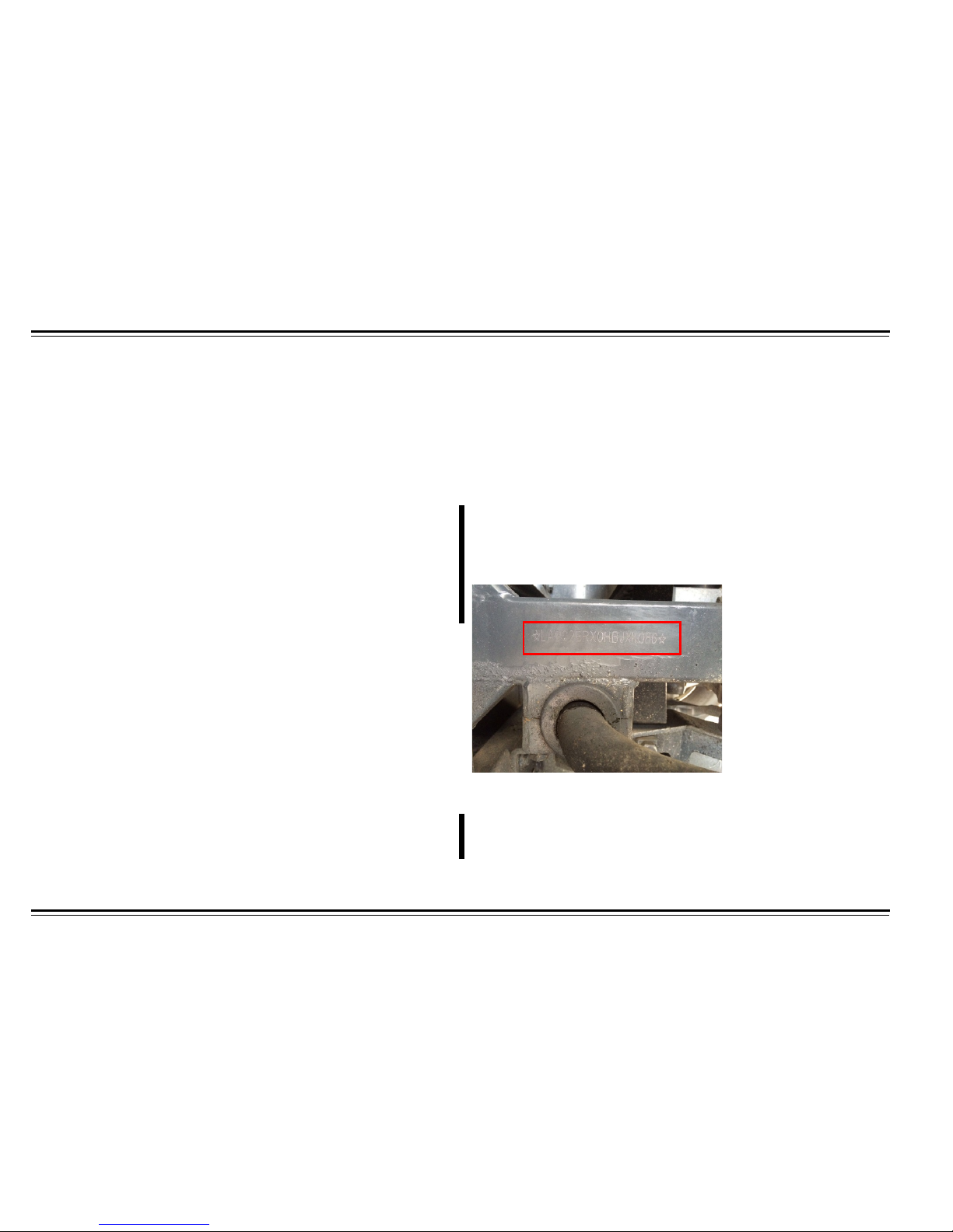
Second Location for VIN Number
The second VIN number is located front right wheel well chassis frame
of the coach. The VIN has been stam ped on the bod y understruc tur e .
A third is located at passenger side 2
nd
luggage bay at frame.
Engine Plate
The engine plate is located on the center of the engine and to the right
side of the fuel filter. The engine plate has the following information on
it: engine model, engine serial number, and arrangement numbers.
Page 8

INTRODUCTION
3
Motor Coach SPECIFICATIONS
Overall Length . . . . . . . . . . . . . . . . . . . . . . . 45 ft 6 in (13.9 m)
Overall Height . . . . . . . . . . . . . . . . . . . . . . . 12 ft 4 in (3.7 m)
Overall Width . . . . . . . . . . . . . . . . . . . . . . . . 8 ft 6 in (2.5 m)
Wheelbase . . . . . . . . . . . . . . . . . . . . . . . . . . 24 ft (7.3 m)
Luggage Space Volume Without Lift . . . . . . 430 ft³ (12.2 m
³)
Luggage Space Volume With Lift . . . . . .. . . . 400 ft³ (11.3 m
³)
Overhead Storage Capacity . . . . . . . . . . . . . 117 ft³ (3.3 m
³)
Front Overhang . . . . . . . . . . . . . . . . . . . . . . 7 ft 6 in (2.3 m)
Rear Overhang . . . . . . . . . . . . . . . . . . . . . . . 9 ft 1 in (2.8 m)
Turning Radius . . . . . . . . . . . . . . . . . . . . . . . . 45 ft 6 in (12.6 m)
Fuel Tank Capacity. . . . . . . . . . . . . . . . . . . . 210 gal (795 L)
Floor-to-Ceiling Height . . . . . . . . . . . . . . . . . 6 ft 5 in (2 m)
GVWR . . . . . . . . . . . . . . . . . . . . . . . . . . . . . 54,000 lb (24,494 kg)
Front Axle. . . . . . . . . . . . . . . . . . . . . . . . . . . . 16,500 lb (7,484 kg)
Drive Axle. . . . . . . . . . . . . . . . . . . . . . . . . . . 26,000 lb (11,793 kg)
Tag Axle . . . . . . . . . . . . . . . . . . . . . . . . . . . . 16,500 lb (7,484 kg)
BODY STRUCTURE
The semi-monocoque bod y truss structure is closed by U-shaped body
assemblies. A skeleton is formed by welded rectangular galvanized
square tubing, made from Australian dual-galva nize d s teel, gi ving
rigidity, stiffness, and torsional resistance. Welded segments are
anticorrosion treated before final assembly.
ELECTRICAL SYSTEM
Controller Area Network (CAN) system architecture with MultIC and
four IOUs. TFT Multifunction display / instrument panel.
Voltage . . . . . . . . . . . . . . . . . . . . . . . . . . . 24VDC
Alternator (dual) . . . . . . . . . . . . . . . . . . . . 24V 140A Prestolite
®
Batteries (OPTIMA) . . . . . . . . . . . . . . . . . 24V 975A
Combination instrument panel incl udes : odometer, tachometer,
intelligent signal processor, voltage meter, water thermometer, oil
pressure gauge, fuel-level gauge, air-pressure gauge together with the
indicators such as steering indicator and high beam indicator.
Page 9

INTRODUCTION
4
ENGINE SPECIFICATION
Cummins ISX12 425 EPA2013
Cylinders . . . . . . . . . . . . . . . . . . . . . . . . . . 6 inline
Bore . . . . . . . . . . . . . . . . . . . . . . . . . . . . . 5.12 in (130 mm)
Stroke . . . . . . . . . . . . . . . . . . . . . . . . . . . 6.18 in (157 mm)
Displacement . . . . . . . . . . . . . . . . . . . . . . 12.5 L (763 cu in)
Weight . . . . . . . . . . . . . . . . . . . . . . . . . . . 2,880 lb (1,306 kg)
Horsepower . . . . . . . . . . . . . . . . . . . . . . . 425 @ 1800 rpm
Torque . . . . . . . . . . . . . . . . . . . . . . . . . . . . . 1,450 lb-ft @ 1200 rpm
Standard Equipment
•
Diesel particulate filter
•
Electronic Control Module (ECM)
•
Electronic Data Link, SAE/ATA, SAE/J1939
•
Electronically Controlled Unit Injection Fuel System
•
Governor: full-range, electr onically controlled
•
Hydraulic steering pump drive, SAE A
•
Lubrication: gear-driven pump, front or rear sump pan, full flow
spin-on filter, oil filler, oil level gauge (dipstick)
•
Open crankcase ventilation
•
Pad mount air conditioner compressor
•
Engine mount alternators
•
SAE No. 1 Flywheel Housing
•
Series-turbochargers
•
Vibration damper
Page 10

INTRODUCTION
5
TRANSMISSION SPECIFICATIONS
Allison B 500R Transmission
•
Allison Transmission has built a reputation on their ability to build
transmissions that last just about forever. That is why Allison
Automatics are the preferred choice for many large, well-known
transit and charter bus fleets.
•
When you factor in all life cycle costs along with the increased
productivity, an Allison Automatic-equipped vehicle costs less per
mile to operate than a comparable competitively equipped vehicle.
•
On a vehicle with an automated manual transmission, the power
interrupts that occur during shift changes result in lower average
wheel horsepower. With an Allison Automatic, there is no power
interrupt during shift changes so Allison Automatic’s can make full
use of the engine’s horsepower. No power interrupts also
contribute to a smoother ride.
Gear Ratios
1st gear .................................................. 3.51:1
2nd gear ................................................. 1.91:1
3rd gear .................................................. 1.43:1
4th gear .................................................. 1.00:1
5th gear .................................................. 0.74:1
6th gear .................................................. 0.64:1
Reverse gears . . . . . . . . . . . . . . . . . . . . -4.8:1
Transmission Continued
Allison B 500R Features and Benefits:
•
Six forward speeds, one reverse.
•
Its dynamic shift sensing automatically selects between lower and
higher speed shift schedules based on the vehicle’s weight and the
grade on which it’s operating.
•
It features a set of low and “super” low speed shift schedules
designed to keep the engine speed at its optimum point, maintaining
necessary performance without shift cycling.
•
The transmission moves neutral at stop to reduces or eliminates the
load on the engine while the vehicle is stopped, reducing fuel usage
and emissions.
•
Its acceleration rate management mitigates aggressive driving
practices by automatically controlling engine torque. The intensity of
control is determined by the vehicle’s weight and grade on which it’s
operating.
•
To get the most out of every drop of fuel, Allison 5th Generation
Electronic Controls offer an enhanced array of smart controls
designed to increase fuel economy and fuel efficiency for the
specific needs of buses.
Page 11

INTRODUCTION
6
SUSPENSION
Front Axle
ZF RL75E (2016)
RL85E (2017)
Double A-shaped beam axle, airbag suspens ion, t wo leve ling va lves
with two airbags, two telescopic shock absorbers and lateral stabilizer.
Front wheel orientation: Wheel camber 0.5º - 1º. Approaching 1º is
recommended. The angle difference should not exceed 0.3º on both
sides.
Kingpin inclination . . . . . . . . . . . . . . . . . . .7.5º+/- 0.5º
Castor . . . . . . . . . . . . . . . . . . . . . . . . . . . .2.30º
Toe-in . . . . . . . . . . . . . . . . . . . . . . . . . . . .0mm +/-1mm
Driving Axle
ZF A132
Integrated press-welding axle housing, full-floating axle shaft, single
reduction final drive hyperbolic gear.
Final gear ratio . . . . . . . . . . . . . . . . . . . . . . . . . . . . . . 4.27/1
All airbag suspension, two leveling valves with four airbags, four
telescopic shock absorbers and lateral stabilizer.
Tag Axle
ZF RL85A TAP
Integrated I-shaped beam, with adapted steering control. Airbag
suspension, two airbags, two telescopic shock absorbers and air
pressed control braking system disc brake.
STEERING SYSYTEM
Power Steering
ZF8098
Recirculating ball-type power steering system.
WHEELS AND TIRES
Wheel type Hub Pilot Alcoa
®
wheels.
Tire specifications (front and rear) . . . . . Michelin 315/80R22.5
BRAKING SYSTEM
Dual-circuit air braking ABS and self-correcting adjusting arm. Air
pressure servo assist with identical disc brakes at all w heels. Manual
valve operated parking brake, energy storage spring works on rear
brake.
Emergency brake effected with parking brake.
Page 12

SAFETY
7
SAFETY
OPERATOR PRECAUTIONS
The following precaut ions have been prepare d f or your safety and the
safety of your passengers and fellow motorists. Read and understand
this information before operating the motor coach.
The safe and reliable operation of this vehicle includes a thorough
working knowledge of all its components. When checking the vehicle
over or driving it, you should be able to recognize problems when they
exist and determine if your motor coach can be driven without affecting
its safe operation or causing more serious mechanical problems. When
work is required, you should be able to report accurately on the
problem.
WARNING
Before starting engine, ensure the transmiss ion is in neutral and
the parking brake is engaged.
WARNING
Prior to performing any checks, maintenance, or repair
procedures, ensure that motor coach is disabled to avoid serious
injury or death. When conducting checks, reme m ber to keep a
safe distance away from moving parts.
WARNING
Do not unnecessarily idle the engine. Do not operate the engine
without an efficient exhaust removal system. Carbon monoxide
gas is toxic. Breathing it can cause unco nsciousn ess and even
death.
WARNING
Use extreme caution while under motor coach, as motor coach
can suddenly drop when air is intentionally or un intentionally
removed from the suspension. Ensure parking brakes have been
applied and the wheels remaining on the ground are secur ed with
wheel chocks. Use properly sized jacks with the appropriate lifting
power. Always use proper chassis stands under a jacked up motor
coach.
WARNING
Never open the engine cooling system or the interior heating
system while the system is hot. Never add cold coolant to an
overheated engine. Do not place unprotected hands on a hot
engine, transmission, or exhaust.
WARNING
Safely depressurize systems containing compressed air or liquid
under pressure prior to opening system.
WARNING
Refuel outdoors and use extreme caution while refue ling.
Page 13

SAFETY
8
PASSENGER SEATBELTS
Each passenger seat is equipped with a lap belt. Designed to
comfortably keep each passenger safely in the seat.
Why wear seat belts
•
Seat belts are the single most effective safety device for adults and
larger children (infants and smaller children must be properly
restrained in child seats.
•
Not wearing a seat belt properly increases the chance of serious
injury or death in a crash.
•
Keep you connected to the vehicle so you can take advantage of
the motor coaches built-in safety features.
•
Help protect you in almost every type of crash; including side, rear
impacts, and rollovers. In a rollover crash, an unbelted person is
more likely to die than a person wearing a seat belt.
•
Help keep you from being thrown against the inside of the motor
coach and against other passengers.
•
Keep you and your passengers from being thrown out of the motor
coach.
Of course, seat belts cannot completely protect you or your passengers
in every crash. But in most cases, seat belts can reduce your risk of
serious injury.
What should you do:
•
Always wear your seat belt properly and make sure your
passengers do as well.
WARNING
If a seat belt does not seem to work as it should, it may not protect
the occupant in a crash. No one should sit in a seat with an
inoperative seat belt. Anyone using a seat belt that is not working
properly can be seriously injured or killed.
Contact CHTC (USA), INC. 800-216-6788 as soon as possible
for parts or repairs.
WARNING LABELS
Warning labels warn you of potential hazards that could cause serious
injury. Read all warning labels carefully and follow instructions on them.
Learn and watch for labels.
If a label comes off or becomes hard to read, contact CHTC (USA),
INC. 800-216-6788 as soon as possible
ROAD SAFETY
The motor coach has been equipped with three reflective roadside
emergency safety triangles that are to be deployed while motor coach is
disabled. After opening the kit, unfold the triangle and ensure it locks
into place.
Page 14
SAFETY
9
FIRE EXTINGUISHER
WARNING
Inspect the fire extinguisher monthly to make sure it has a
sufficient charge. Look at the gauge at the top of the extinguisher
to verify proper charge.
WARNING
Safely evacuate motor coach prior to fire exting uisher use.
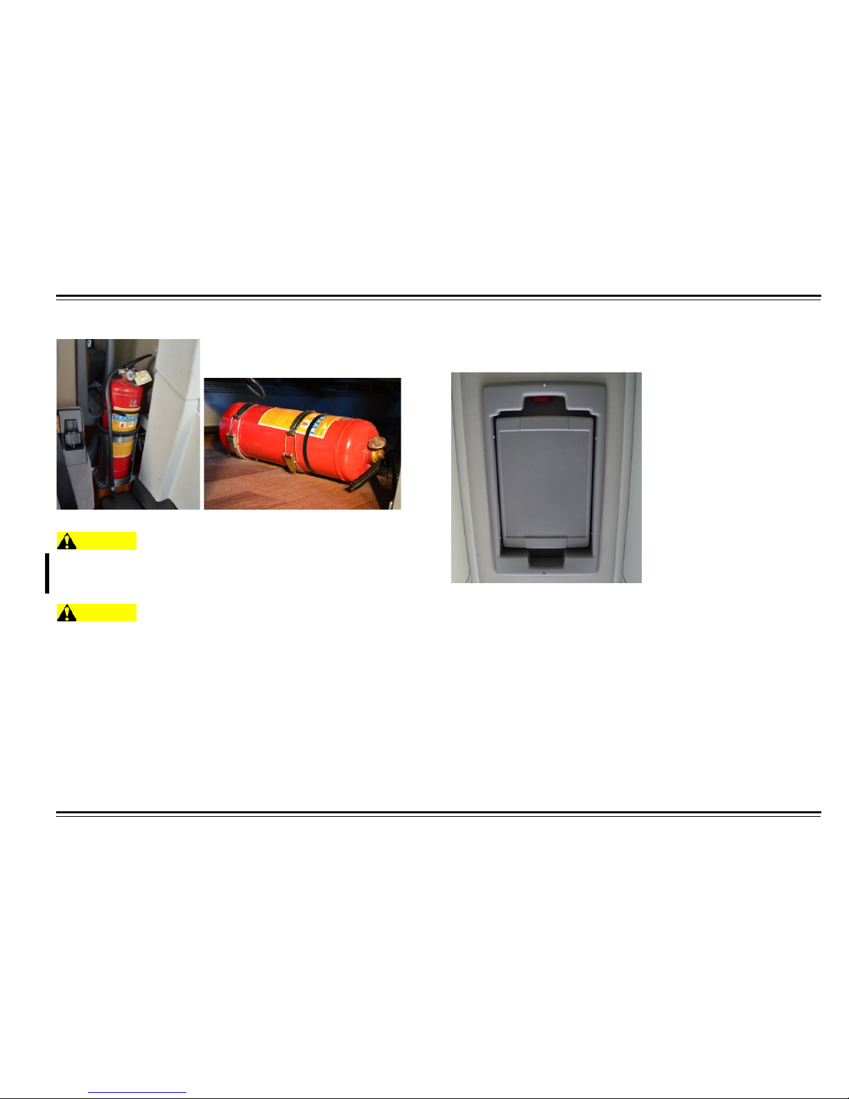
Fire extinguishers are located under first isle passenger seat and at
rear wall of lavatory compartment. To remove, release latch and lift.
Follow instructions on fire extinguisher.
Under 1
st
passenger seat.
EMERGENCY EXITS
Emergency Roof Escape Hatch
There are two escape hatches located in the roof for emergency exit of
the motor coach. The hatch is also used as a ventilation for passenger
compartment.
In case of emergency, pull red handle and push hatch open fully.
Proceed to exit the motor coach safely.
Page 15
SAFETY
10
Emergency Escape Windo w
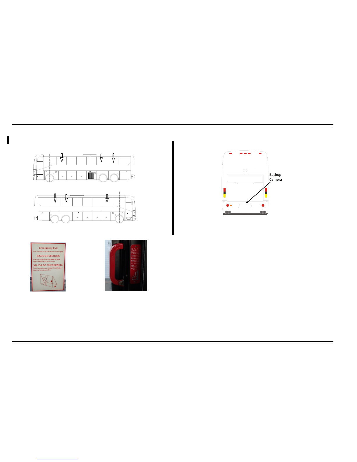
The motor coach is equipped with three emergency exit windows on
the left side and three on the right side. The emergency window can
be opened by lifting the red handle and pushing the window out.
Proceed to exit the motor coach safely. Instruction labels are on each
escape window. Regularly inspec t all em er gency windows to ensure
latch is secure.
Integrated Backup Camera
This backup camera and radar sees not only what is behind the motor
coach, but also gives an estimated distance to the nearest object.
Page 16
11
SAFETY
CONTROLS
INSTRUMENT PANEL
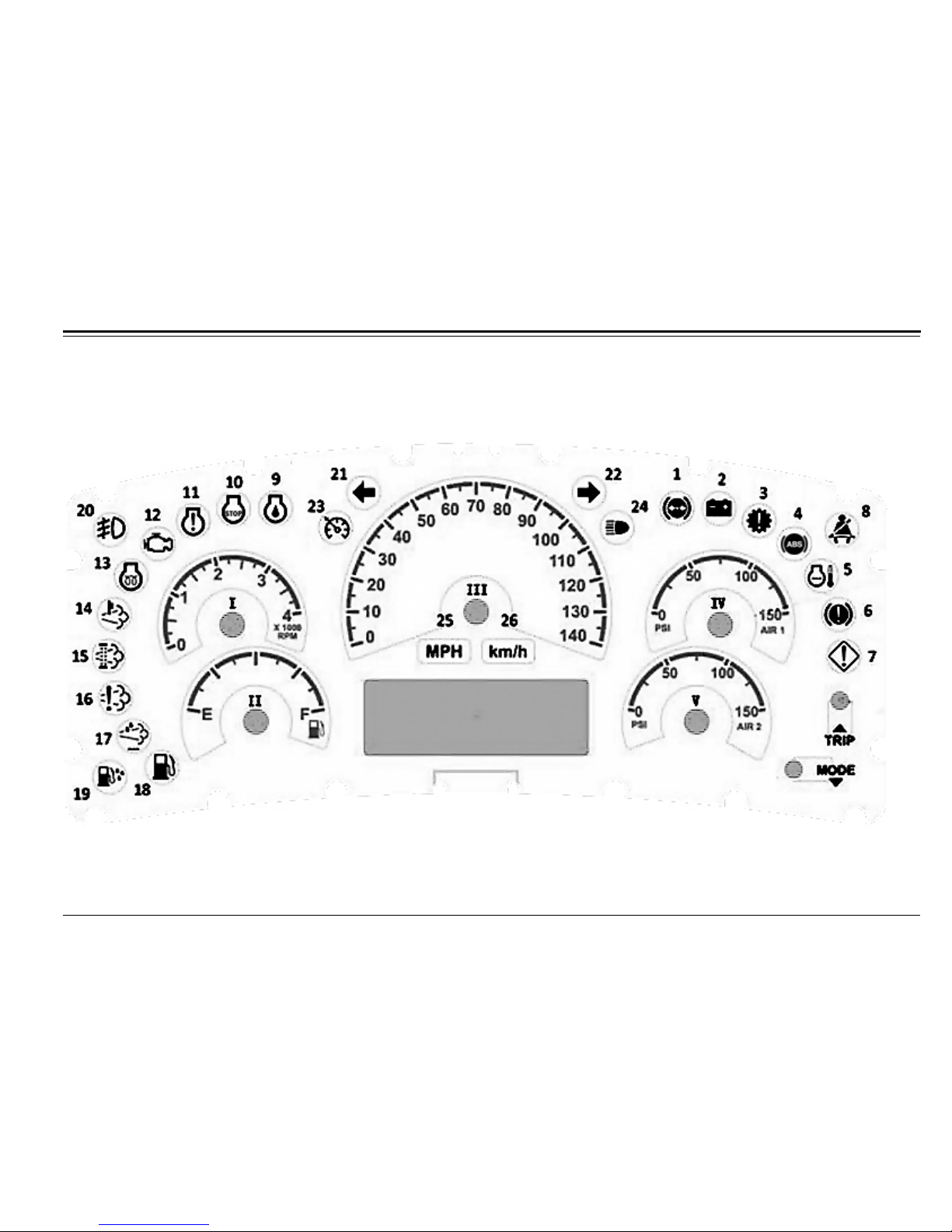
The instrument panel and controls are designed to provide the driver with the ability to monitor and control the operation of the motor coach.
Page 17
CONTROLS
12
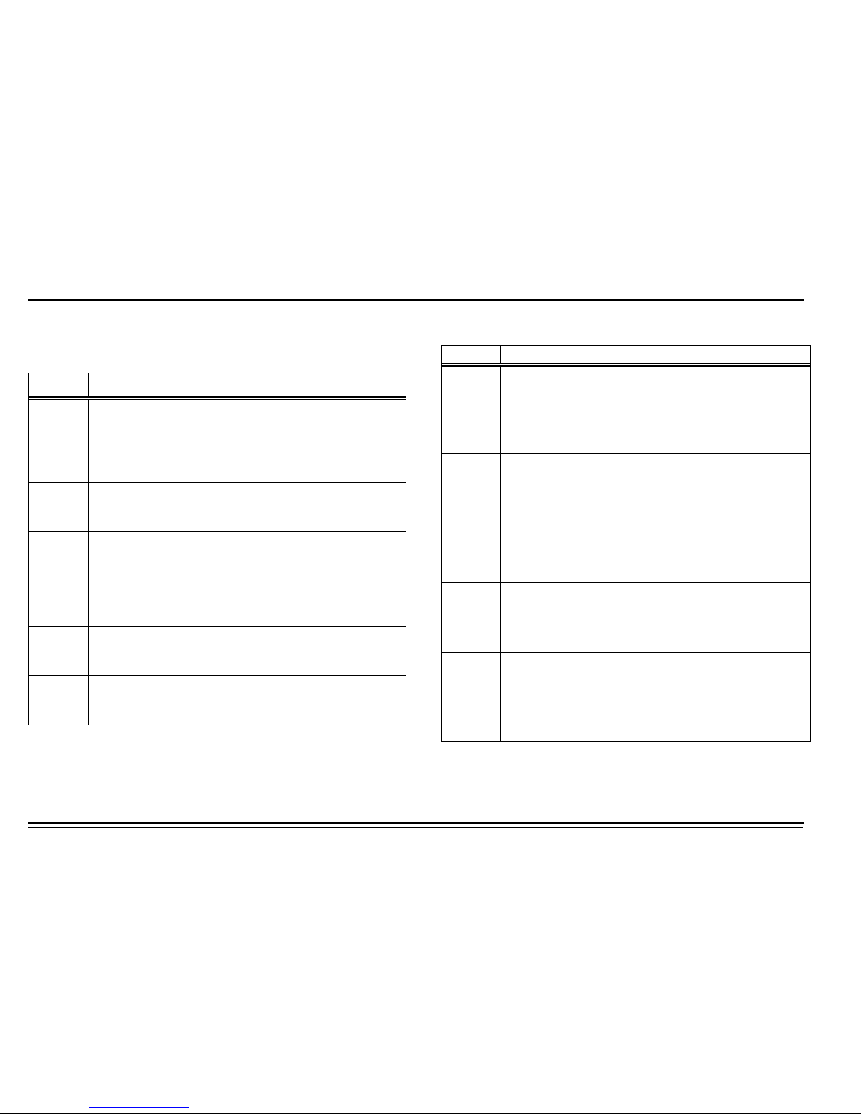
Table 1: Instrument Panel Face
Table 1: Instrument Panel Face
Number Item
1
Brake Pad Wear Indicator
This light appears when the brake pad is worn and thin.
2
Battery Warning Indicator
The light appears when battery failur e occurs and needs
to be replaced.
3
Check Transmission
When transmission electronic control unit detects errors
on the transmission, this light will appear.
4
ABS Fault Indicator
When an error occurs with ABS system, this light will
appear.
5
Engine Coolant Hot
When engine coolant temperature is high, this li ght wi ll
appear.
6
Park Brake Applied
When the vehicle has stopped and the driver applied
parking brake, this light will appear.
7
Brake System Warning
When electronic system found air pressure is under 6
bars, this light will appear.
Number
Ite
8
Seatbelt Warning
If driver is not wearing seat belt, this light will appear.
9
Engine Oil Pressure
When the electronic system find engine oil pressure
does not match calibration data, this light will appear.
10
Engine Fault Stop
Engine is not operating pr o per ly. Engine may derate,
with reduced power or speed if problem is detected.
Action: bring vehicle to safe stop as quickly as possible
and have vehicle serviced before resuming. Note: if
engine shuts down and vehicle is still on the road it may
be possible to restart for brief period (approximately 30
seconds) after turning the ignition off to allow vehicle to
be moved to safe location.
11
Engine Fault Warning
Engine is not operating properly. Engine may derated,
with reduced power or speed if problem is detected.
Action: seek a service facility to address the registered
fault code at the earliest opportunity.
12
Engine Malfunction Indicator Lamp
The light indicates that the electronic system has
detected malfunction related to emission control
system and the after-treatment system should be
diagnosed and serviced at your next available
opportunity.
Page 18
CONTROLS
13
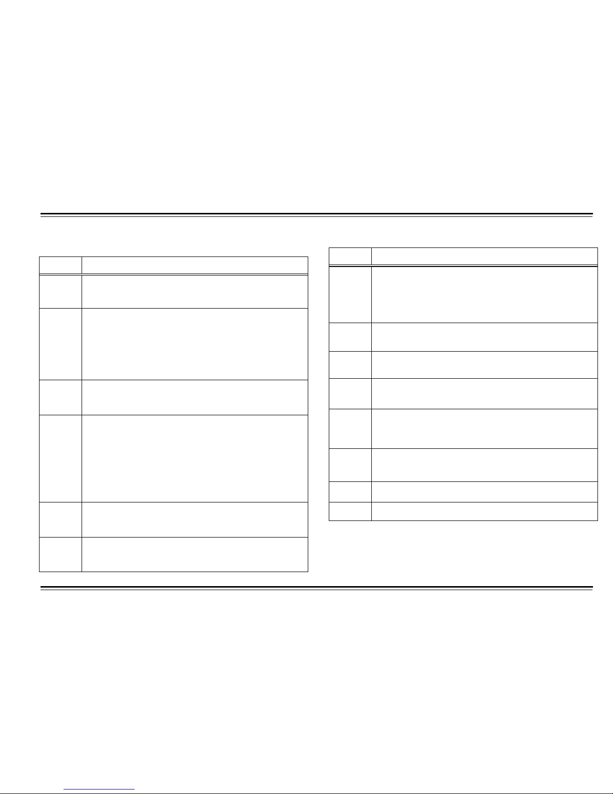
Table 1: Instrument Panel Face
Table 1: Instrument Panel Face
Number Item
19
Water in Fuel
Water has been sensed in fuel filter assembly. This can
cause the engine to run rough and be difficult to start.
Action: water must be drained from fuel filter assembly.
Have vehicle serviced as soon as possible.
20
Fog Lights
This light indicates that the fog lights are turned on.
21
Left Turn Indicator
This light indicates that the turn left signal is on.
22
Right Turn Indicator
This light indicates that the turn right signal is on.
23
Cruise Control
When the TFT screen is used for reverse monitor, this
button is used to turn on the Brightness Function.
24
High Beam
This light indicates that the high beam is on.
25
MPH Indicator
26
km/h Indicator
Number Item
13
Glow plug
Wait to start engine preheat. Do not start engine until
after light goes out.
14
High Exhaust System Temperature (HEST)
The light indicates that high exhaust temperatures may
exist due to after treatment regeneration. This is normal
and does not signify the need for any kind of vehicle
service or engine service. When this lamp is illuminated,
ensure that the exhaust pipe outlet is not directed at any
combustible surface or material
15
DPF Status Indicator
This light indicates that DPF regeneration is required.
16
Exhaust After Treatment Warning
This light indicates that the after treatment DPF
requires regeneration. This is accomplished by the
following:
1. If the vehicle is equipped with regeneration inhibit
switch, ensure that the switch is not in inhibit position.
2. Perform DPF regeneration by one of the following:
a. Change to a more challenging duty cycle such as
highway driving for at least 20 minutes.
17
Low DEF
This light indicates that the DEF level is low.
18
Low Fuel
When diesel fuel level is low, this light will appear.
Page 19
CONTROLS
14
Number Item
1
Washroom Emergency Label
This symbol appears when the emergency switch inside the WC
was pressed.
2
Washroom Working Indicator
This symbol appears when the WC is being used.
3
Washroom Water Level Warning
This symbol indicates that the WC water tankard level is low.
4
Disabled Pedal Indicator
5
Passenger Service Indicator
Table 1: Instrument Panel Face
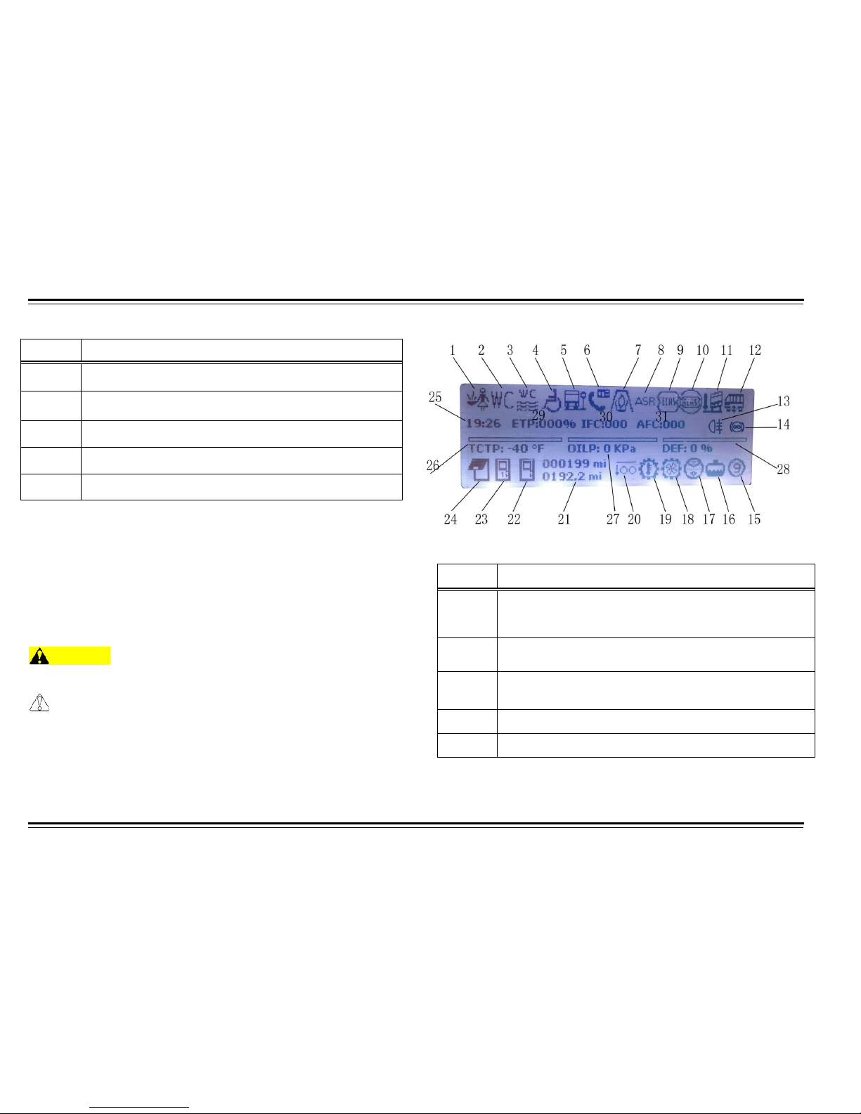
Normal TFT Screen
Table 2: Normal TFT Screen
WARNING
When the Stop Light is on, you must stop the motor coach and
solve the problem.
CAUTION
When you are welding on the motor coach, you must disconnect
the MultIC and IOUs from the power supply and disconnect the
batteries. Do not directly spill or spray any liquid on the MultIC and
IOUs. Do not allow objects to touch lens of MultIC.
Number Gauges
I
Engine RPM
II
Fuel Level
III
Speedometer
IV
Air Pressure 1
V
Air Pressure 2
Page 20
CONTROLS
15
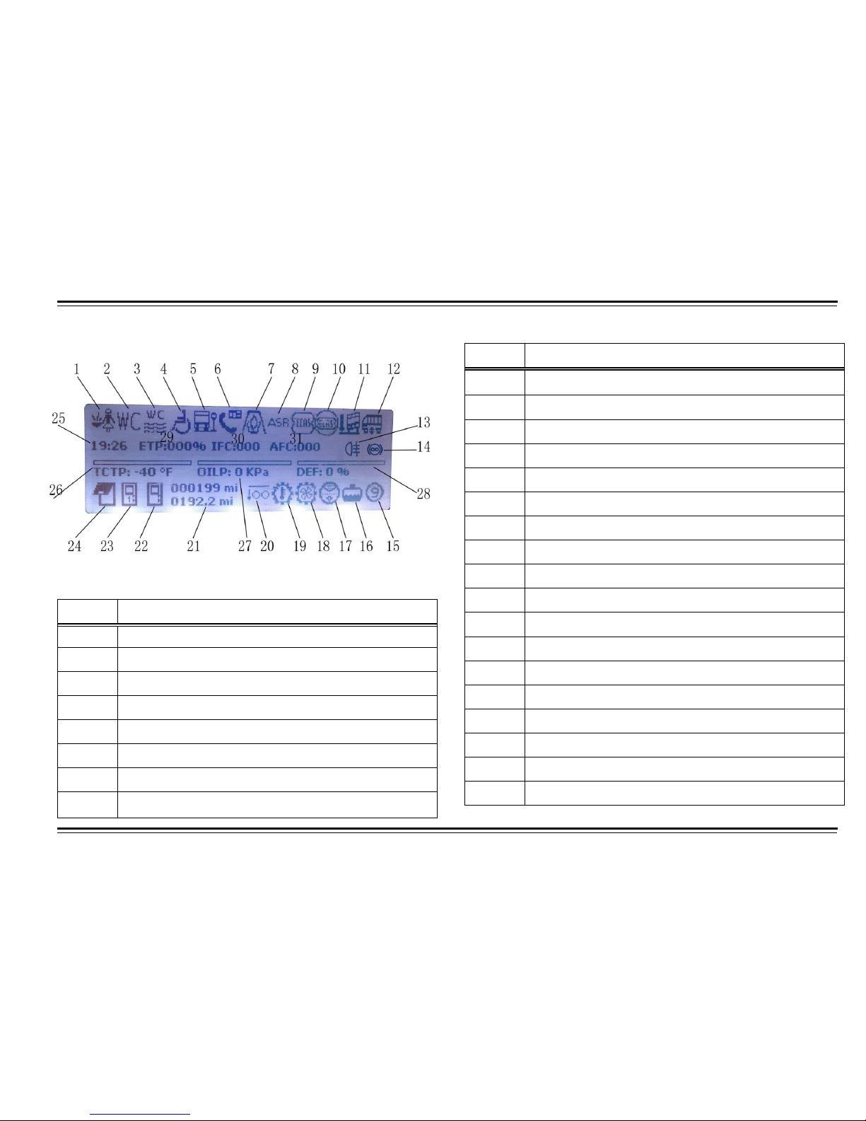
TFT Screen Indicator Symbols
Table 3: TFT Screen Indicator Symbols
Table 3: TFT Screen Indicator Symbols
Number Item
6
Disabled Service Requirement
7
Heater Working Indicator
8
ASR System Functional or Error Indicator
9 ECAS Warning Indicator
10
EACS Error Indicator
11
ECAS Kneeling Indicator
12
Body State Indicator
13
Fog Lamp Indicator
Letter Item
14
Retarder Functional Indicator
15
Transmission Gear Indicator
16
Cooling Water Level Warning Indicator
17
Air Filter Warning Indicator
18
Hydraulic Fan Warning Indicator
19
Transmission Oil Temperature Warning Indicator
20
Tag Axle Release Pressure Indicator
21
Kilometer/mileage Display
22
Emergency Door Indicator
23
Passenger Door Indicator
24
Engine Cabin Door Indicator
25 Time Display
26
Engine Temperature
27 Engine Lubrication System Pressure
28 Adblue Liquid Level Display
29 Accelerator Pedal Position Display
30 Current Fuel Consumption
31 Average Fuel Consumption
Page 21
CONTROLS
16
SWITCH PANELS
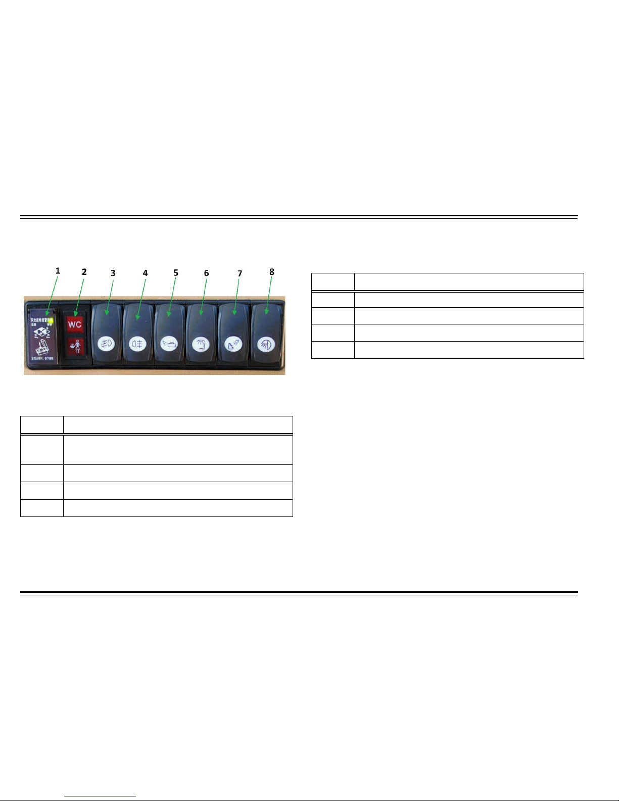
Upper Left Switch Panel
Table 4: Upper Left Switch Panel
Table 4: Upper Left Switch Panel
Number Item
1 Automatic Fire Suppression System Stand-by
(Only operate in case of engine fire)
2
WC Emergency Indicator and Level
3
Front Fog Lamp Switch
4
Rear Fog Lamp Switch
Number Item
5
Luggage Compartment Light Switch
6
Driver Light Switch
7
Step Light Switch
8
Docking Lights Switch
Page 22
CONTROLS
17
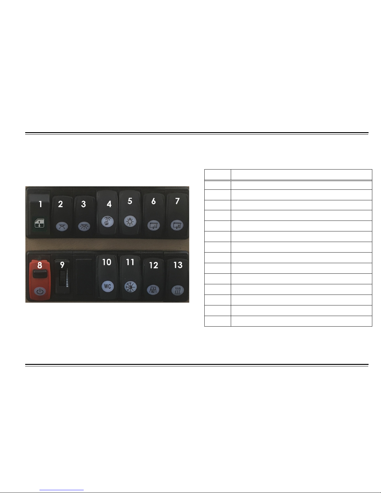
Table 5: Lower Left Side Switch Panel
LOWER LEFT SWITCH PANEL
Number Item
1
Window Switch
2
Yellow Daylight Switch
3
White Daylight Switch
4
Passenger Reading Light Switch
5
Blue Overhead L.E.D. Switch
6
Left Sun Visor Switch
7
Right Sun Visor Switch
8
Main Power Switch
9
Dash Light Dimmer
10 Rear View Mirror Defrost Switch
11 Wash Compartment Activation Switch
12 A/C Economy Switch
13 SPHERO Heater Activation Switch
14 Hydraulic Fan Drive Switch (Speed)
Page 23
CONTROLS
18
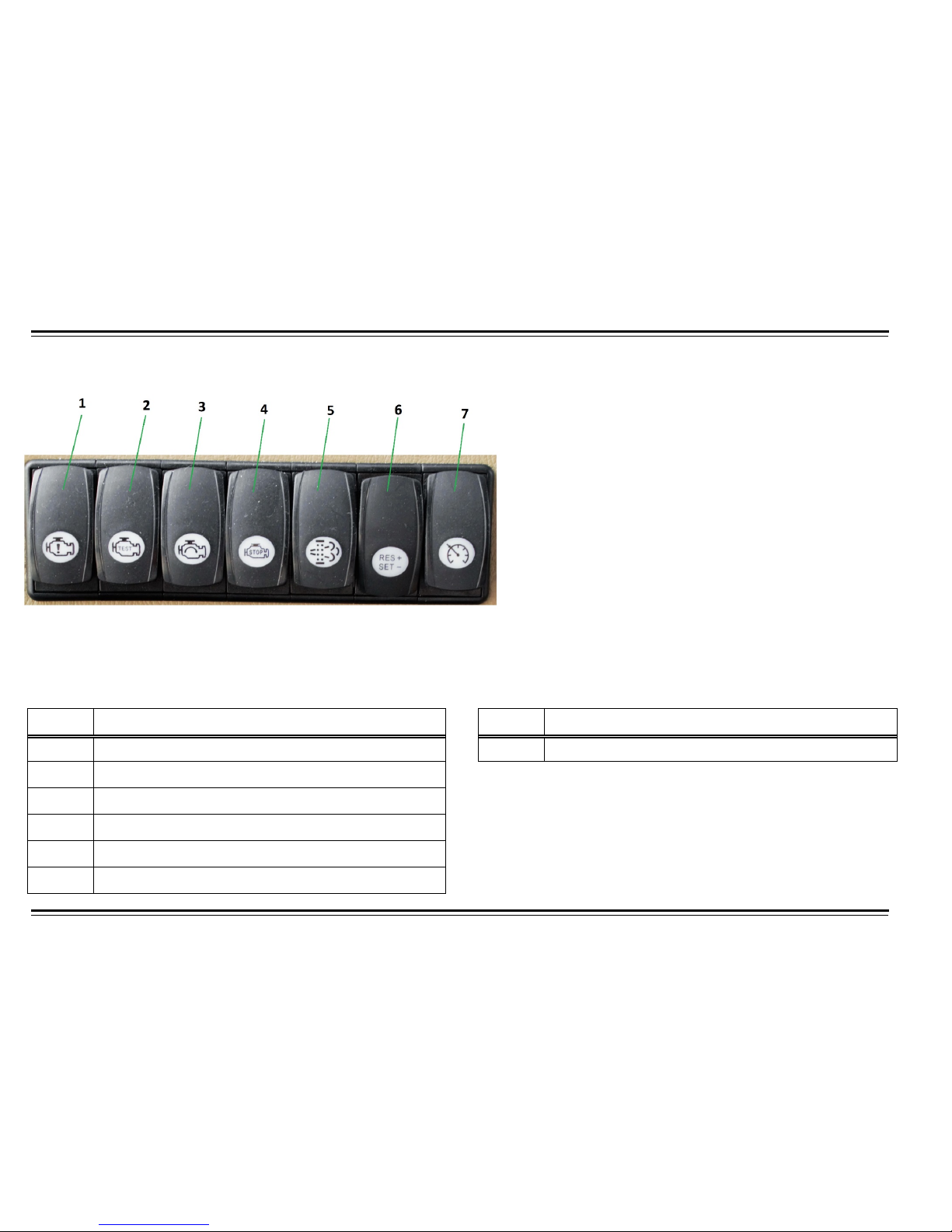
Right Side Upper Switch Panel
Table 10: Right Side Switch Panel Table 10: Right Side Switch Panel
Number Item
1
Engine Air Intake Stop Switch
2
Air Intake Close Test Switch
3
Outage Protection Cover Switch
4
Outage Protection Switch
5
DPF Inhibited Regeneration Switch
6
Cruise Control Speed/Resume/Set Switch
Number Item
7
Cruise Control Activation Switch
Page 24
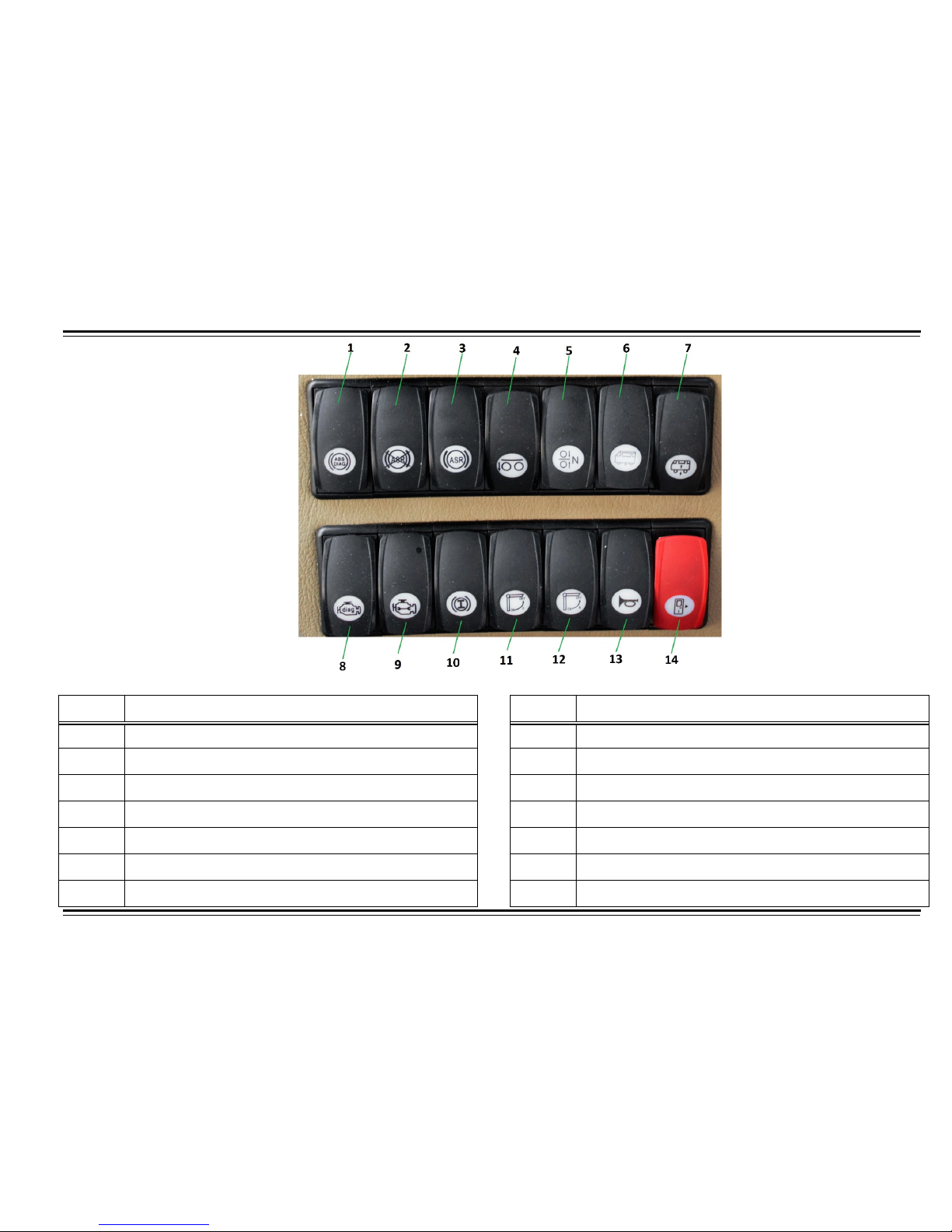
CONTROLS
19
Right Side Lower Switch Panel
Table 10: Right Side Switch Panel Table 10: Right Side Switch Panel
Number Item
1
ABS Diagnosis Switch
2
ASR Shut Down Switch
3
ASR Switch
4
Tag Axle Bleed Valve Switch
5
Back to Normal Height Switch
6
Kneeling Switch
7
Body Lift/Lower Switch
Number Item
8
Diagnosis Trigger Switch
9
Limp Home Switch
10
Retarder On/Off Switch
11 TV Monitor Flip Down Switch
12 TV Monitor (Spare Switch)
13 Air Horn Switch
14 Passenger Entrance door switch
Page 25
CONTROLS
20
CLIMATE CONTROLLER
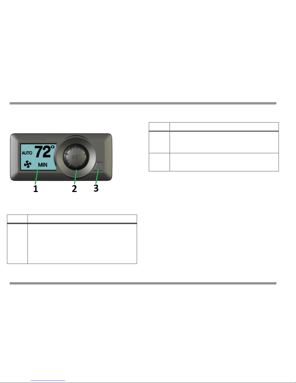
Driver Climate Controller
Table 6: Driver Climate Controller
Table 6: Driver Climate Controller
Main Screen: When the MVC is powered on, it displays mode, set-
point and fan speed. Temperature set-point can be changed in this
menu.
Fan Speed Screen: To change fan speed, enter the fan speed menu
by press the SET knob once then turn knob to decrease or increase
fan speed
Number Item
2
Set/Select Button
It is used for selecting between menus. In
Test/Diagnostic mode, it is used to test and diagnose
different components with in the HVAC system.
3
Power Button
Turn unit ON or OFF
Number Item
1
LCD Display
During normal operation, the set-point temperature,
blower speed, operation mode and fresh/recirc air
selection are displayed. In Test/Diagnostic menu,
error messages will be displayed on screen for
troubleshooting
Page 26
CONTROLS
21
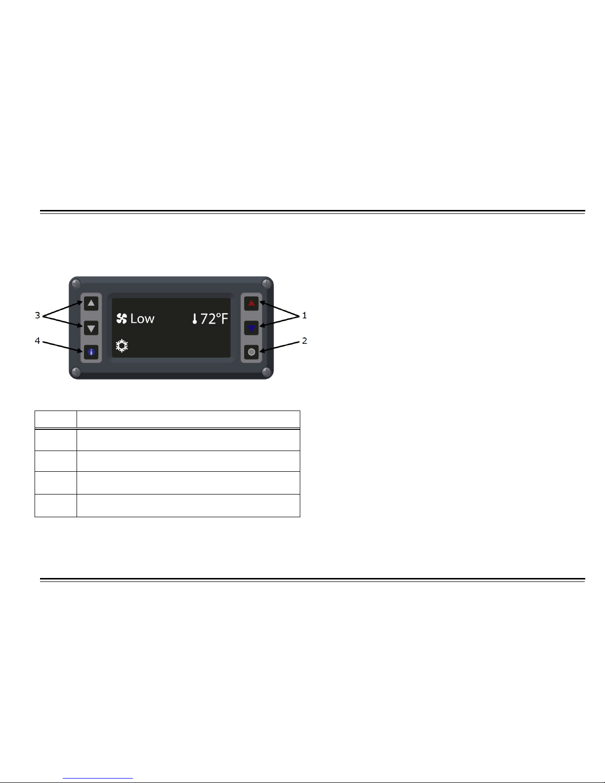
Motor Coach Climate Controller During vehicle maintenance, service personnel can enter diagnostic
mode by pressing preset sequence of buttons or using optional MCC
Coolview via CANBus connection. In this mode, errors stored in
memory and real-time data of inputs and outputs are displayed for
easy trouble shooting
.
Table 7: Motor Coach Climate Controller
Number
Item
1 Temperature Set-point
Adjust temperature for passenger compartment
2 On/Off Button
Turn HVAC system On or Off
3 Cursor
Cursor and mode selection
4 Information
Display system information
Page 27
22
CONTROLS
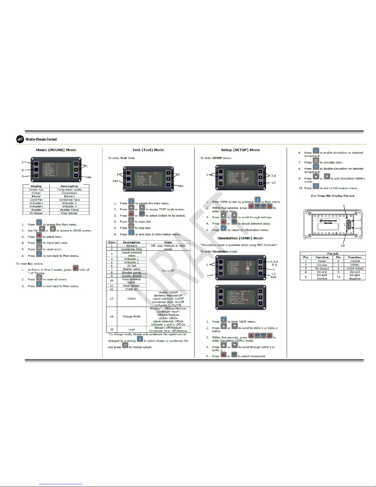
SPHEROS® Auxiliary HEATER
Table 8: Timer Controls
Number Item
1
7-Day Digital Timer Display
2
Day/Time Advance Button
3
Day/Time Reverse Button
4
Heater On/Off Button
5
Program Selection Button
6
Clock Button
WARNING
Due to the danger of poisoning and suffocation, the heater must
not be operated in enclosed areas, such as garages or workshops,
without an exhaust-venting system, not even if the start-up is
activated by the timer or remote start device.
Page 28
23
CONTROLS
WARNING
At filling stations and fuel depots, the heater must be switched off
as there is a potential danger of explosions.
WARNING
Where flammable fumes or dust may build up (e.g. in the vicinity of
fuel, coal, wood, cereal grain deposits, or simi lar situations), the
heater must be switched off to prevent explosions.
CAUTION
Before switching the Sphero heater on, open any shutoff valves
and set vehicle heater controls to the HOT position.
The digital timer with three time settings permits the Sphero heater to
be switched on and off instantly, or automatically at 3 programmable
starting times.
The operating time of the heater can be pre-selected. It is possible to
program three different heating times according to your individual
needs.
Only one preset starting time can be activated at any one time. When
the ignition is switched on, the current time of the day and the day of the
week are displayed.
When the heater is in operation, the display and the buttons of the timer
are illuminated.
Programmed Heater Operation
Three memory locations numbered 1 to 3 are available. Each memory
location can be assigned a given time together with the day of the
week.
Pre-selected Starting Times
The pre-selected starting time is the time at which the heater will be
switched on automatically.
NOTE: Recommended that memory locations 1 and 2 be used for
presetting starting times within a 24-hour period of setting the timer.
Memory location 3 can be reserved for a starting time within the next
seven days of setting the timer. Location 3 is useful for occasional
weekend or field trip operations outside of the normal schedule. By
repeatedly pressing the program selection button on the timer, starting
time pro- gram 1, 2 or 3 can be viewed and preset.
Operating Time
The period of time during which the heater is in operation is referred to
as the operating time. The heater remains in operation for as long as
the operating time has been preset. Heater operation can be
preselected for any time from a minimum of 1 minute (a minimum of 10
minutes is recommended) to a maximum of 120 minutes (factory preset
is 60 minutes).
Page 29
CONTROLS
24
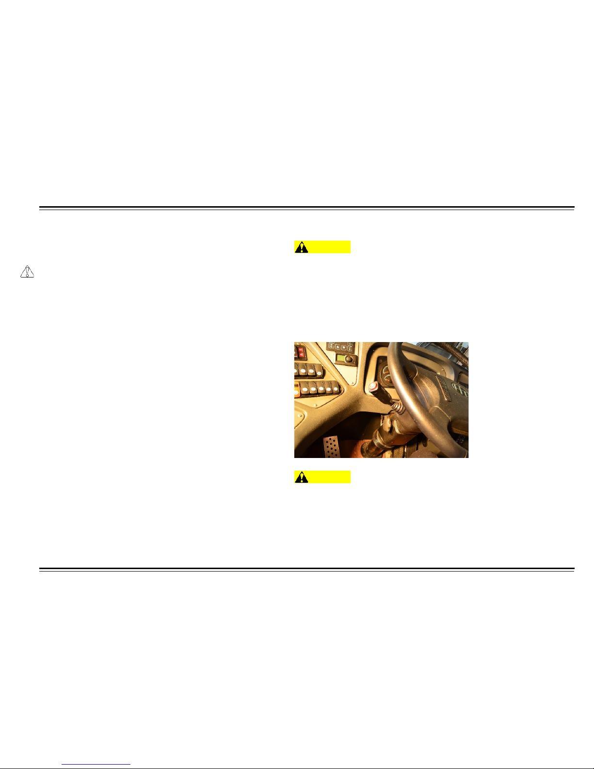
STEERING WHEEL AND COLUMN
The two levers on the steering column contain controls for driving
features you use most often. The left lever controls the turn signals,
headlights, and hazard warning lights. The right lever controls the
windshield washer, wipers, and retarder lever.
Headlights
The rotating switch on the left lever controls the lights. Turning this
switch to the first position turns on the parking lights, taillights,
instrument panel lights, side marker lights, and rear license plate light.
Turning the switch to the second position, turns on the headlights.
To change from low beams to high beams, lift the turn signal lever up
until you hear a click. The blue high beam indicator will light on
instrument panel.
To return to low beams, push the turn signal lever down.
Turn Signals
To signal a lane change, push lightly on the turn signal lever in the
proper direction. The turn signal lever will return to the center position
upon completion of turn.
Hazard Warning Flashers
The left lever controls the hazard warning flashers. Push the button on
the end of the lever to turn on the hazard warning lights (four-way
flashers). This causes all four exterior turn signals and both indicators
in the instrument panel to flash.
Use the hazard warning lights if you need to park in a dangerous area
near heavy traffic, or if your motor coach is disabled.
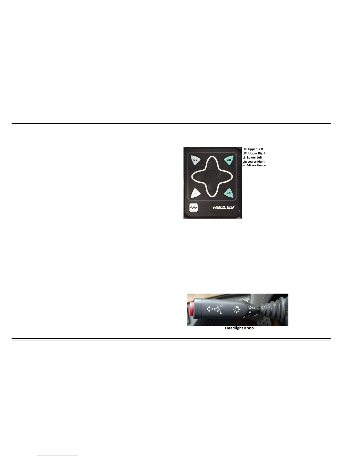
EXTERIOR MIRRORS SELECT/CONTROL MODULE
Exterior mirrors have separate upper and lower segments. The convex
lower portion is for wide angle view. Adjust the exterior mirrors so that
you can see the side of the coach in part of the mirror. This helps
determine the relationship of the coach to objects seen in the mirror.
The left side and right side mirror control is on the upper left hand
console switch panel. Use the mirror select/control module to select
which mirror is to be adjusted. Adjust the mirror using the same control
module. Pass the buttons to the left to adjust the mirror to the left and
to the right to adjust the mirror to the right. Defrost the mirrors using the
mirror heat switch located below the mirror controls on the upper left
switch panel.
Page 30
25
CONTROLS
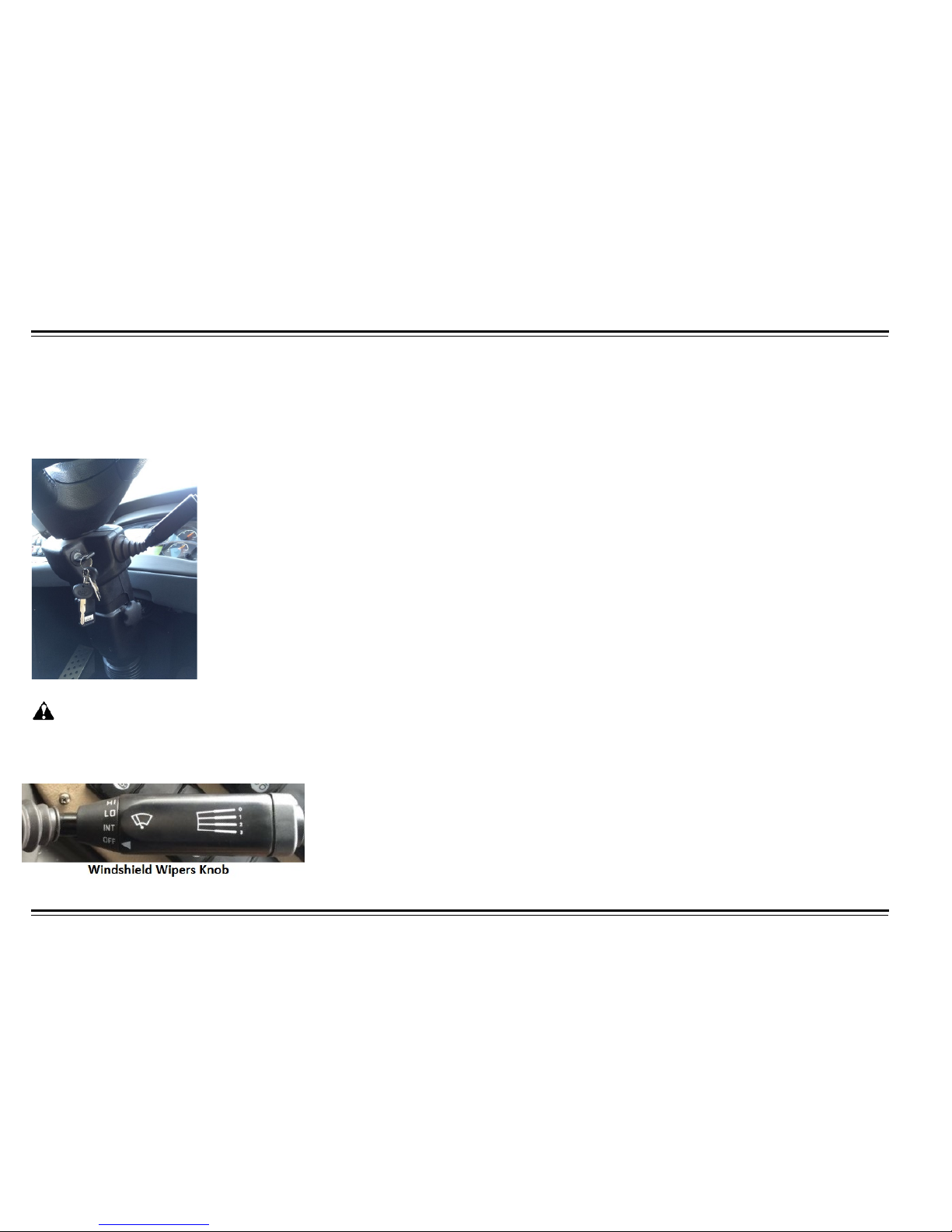
Windshield Wiper Controls
Windshield Wipers
CAUTION
Do not operate wiper in dry conditions. Activate the washers for
proper lubrication before wiper operation.
The rotating switch on the right lever controls the windshield wipers,
including the intermittent wiper control. The rotating switch has four
positions:
•
OFF-Wiper is off.
•
INT-Wiper on intermittent setting.
•
LO-Wiper on low speed setting.
•
HI-Wiper on high speed setting.
Turning this switch to the first position turns on the wiper intermittently,
frequency of the wiper blades depends upon the setting of the delay
switch. In intermittent, the wipers operate every few seconds.
Turning this switch to the second position turns the wiper on a low
speed. In low speed, wipers run continuously.
Turning this switch to the third position turns the wiper on a high speed.
In high speed, wipers run continuously.
Windshield Washer
The right lever controls the windshield washer. To clean the windshield,
push the button on the end of the lever to turn on the windshield
washer. The washer will spray until you release the button.
Steering Wheel Height Control
WARNING
Adjusting the steering wheel position while driving may cause you
to lose control of the motor coach, and to serious ly injure you and
your passengers. Adjust the steering wheel only when the motor
coach is stopped.
Turn lock-handle located on left side of steering column
counterclockwise to adjust steering wheel height. Tighten by turning
lock-handle clockwise.
WARNING
Make sure you have securely locked the steering wheel in place by
trying to move it.
Page 31
26
CONTROLS
Steering Wheel Angle Control
Turn lock-handle located on right side of steering column
counterclockwise to adjust steering wheel angle, then tighten by
turning lock-handle clockwise.
WARNING
Make sure you have securely locked the steering wheel in place by
trying to move it.
Page 32
CONTROLS
27
Ignition Switch
WARNING
Do not turn the ignition key to the OFF position while the motor
coach is moving.
NOTE: In the event of failed start, wait 2 minutes before attempting to
re-start.
NOTE: If a re-start fails, check the fuel supply before any further
attempts.
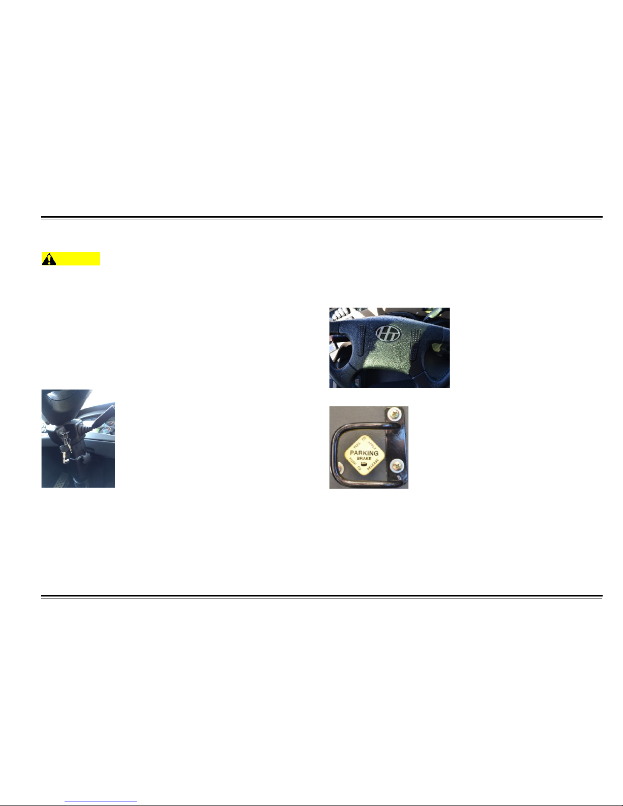
The ignition switch is located on the right side of steering column. The
ignition switch has five positions. The following is an explanation of
those ignition switch positions:
•
LOCK - This pos iti on is us e d f or inser ti ng the key into the ignition
and for withdrawing the key from the ignition. This position is also
used for turning off the engine.
•
ACC - This position is used for powering only the radio and other
accessories.
•
ON - This position is used for the continuous period of engine
operation.
•
START - This position is used for engine startup only. Key will
automatically return to the ON position when released.
Horn
To use the horn, press either horn button located on the top of the
steering wheel center pad. The horn should sound while pressing down
on either button. The horn can be an electric or air horn, the electric/air
horn switch is located on the right switch panel.
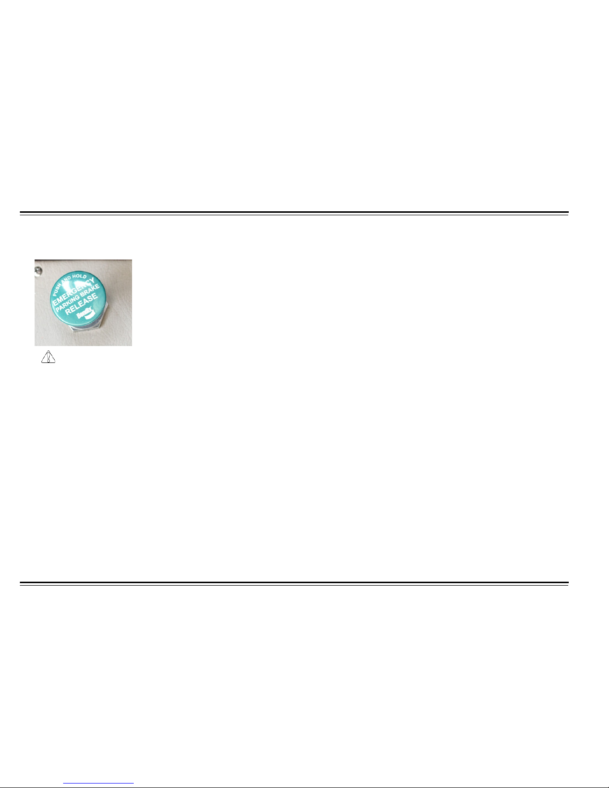
PARKING BRAKE
The parking brake knob is located on the left console of the driver seat.
When the vehicle is stopped, pull out knob to set the parking brake.
When ready to start moving with engine running and primary air supply
at 90 psi, beeper and low air pressure light off. Place foot on brake
pedal and push in knob to release the brake.
Page 33
28
CONTROLS
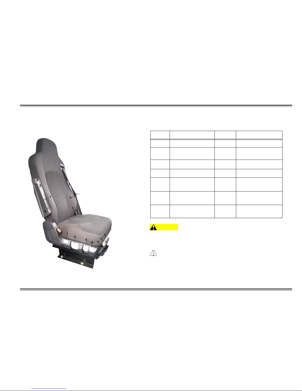
EMERGENCY BRAKE
CAUTION
Motor coach must be stopped prior to activating emergency
brake.
Pull the handle up to engage the emergency brake. Press the handle
down to release emergency brake. In case of parking brake
malfunction, the em ergenc y brak e wil l retur n to t he ori ginal positio n
automatically.
Page 34
29
CONTROLS
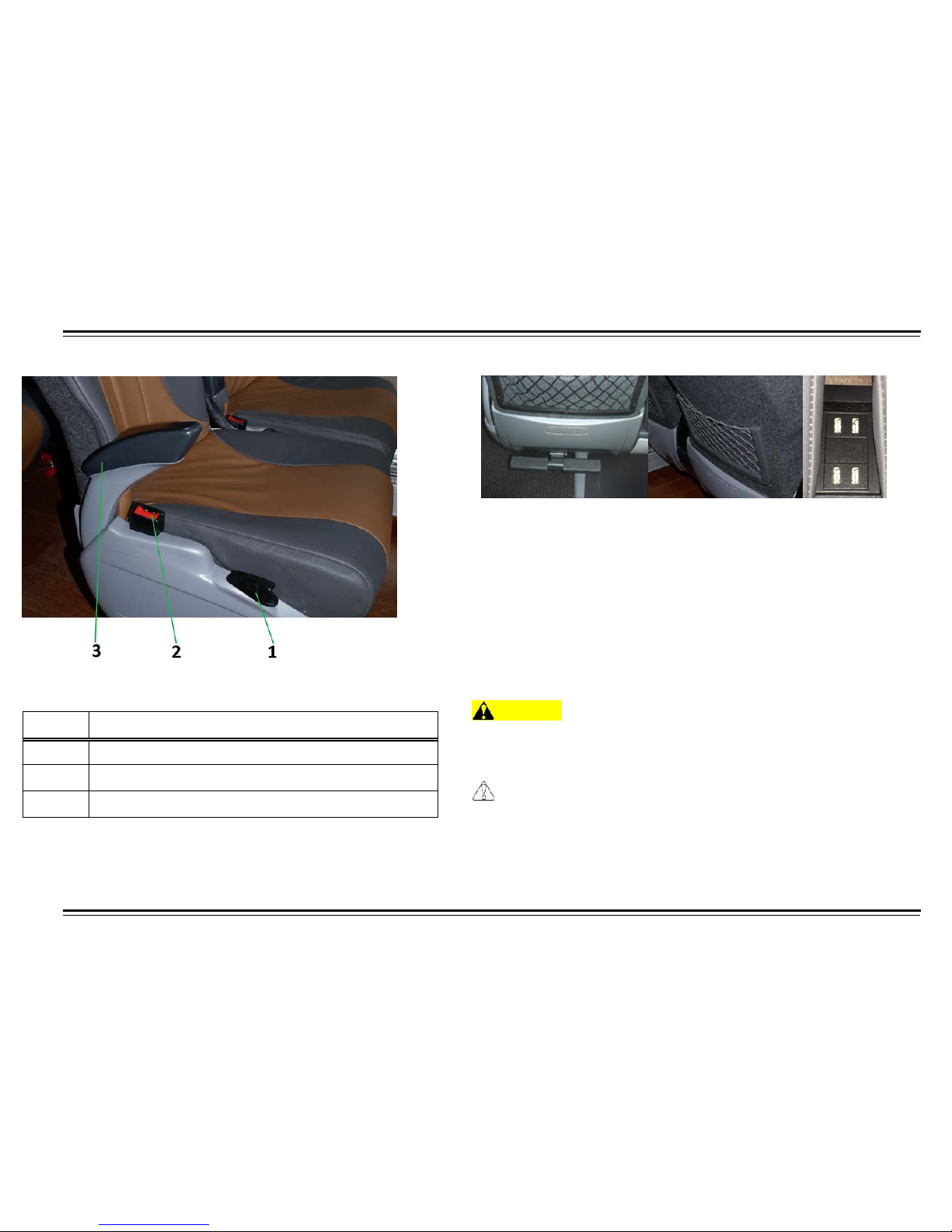
ISRI® Driver’s Seat
The seat can be moved forward and backward. The backrest angle
can be fully adjusted.
Table 11: ISRI Driver’s Seat
Number Item Number Item
1
Armrest Adjuster
8
Height Adjuster
2
Backrest
Adjuster
9
Shock Absorber
Adjuster
3
Horizontal Adjuster 10 Quick Release
4
Tilt Adjuster
5
Seat Cushion
Adjuster
6
Integrated 3 Points
Safety Belt
7
Pneumatic Lumbar
Adjuster
WARNING
Do not adjust the driver’s seat while the motor coach is moving.
The seat could suddenly and unexpectedly move, causing the
driver to lose control of the vehicle.
CAUTION
After making a seat adjustment, always test to ensure that the
adjusters have latched. An improperly latched mechanism could
impair driver abilities.
Page 35

30
CONTROLS
General Information
WARNING
No objects should be placed within the moving area of the driver’s
seat to prevent injury.
WARNING
Settings must be checked to ensure they are correctly engaged
before the motor coach is driven. Adjustments must not be made
while driving.
A correctly functioning and individually adjusted driver’s seat is
essential to good health. Seat is maintenance free. Take adequate
care of your seat to ensure that it functions properly.
CAUTION
Dirt can impair the function of the seat. Keep the seat clean.
Upholstery does not need to be removed from the seat frame for
cleaning.
NOTE: Do not soak through upholstery during cleaning. Do not use
pressure washer to clean seat.
CAUTION
Use standard commercially available upholstery or plastics
cleaning agent. Test for compatibility on a small, concealed area.
Check seat frequently to ensure proper function. Regularly check that
seat is tight. If seat wobbles, check for loose bolts or other faults. To
ensure proper function of the driver’s seat and to prevent damage of
pneumatic spring, adjust the loaded driver’s seat to the highest height
position.
Seat Operation
Height Adjustment
The seat height can be adjusted continuously within a range of 3.9 in.
(99 mm). Pull or press the handle for height adjustment to move the
seat upwards or downwards.
NOTE: Always release the handle after reaching the upper or lower
stop.
Lumbar Support
With front and back switch, the curvature in the upper and lower area of
the backseat upholstery can be adjusted individually.
The air compartments will be filled by setting the respective switch to “+”
and emptied by setting it to “-”.
Lateral Support Adjustment
By actuating the switch, the curvature of the lateral guide right and left
of the backrest can be adjusted individually by means of compressed
air.
By setting the switch to “+”, the air compartments will be filled. By setting
it to “-”, they will be emptied.
Page 36

31
CONTROLS
Backrest Adjustment
Pull up the locking lever to release the backrest catch. The backrest is
brought into the desired position by simultaneously exerting or relieving
pressure. Release the locking lever to lock the backrest.
NOTE: It should not be possible to move the backrest into another
position after it has been locked.
Seat Heater ( OPTIONAL )
By operating the seat heater switch, the heating mats in the backrest
and seat cushion can be heated in two steps.
•
0 = Heater Off
•
1 = Heating step 1 ON
•
2 = Heating step 2 ON
Armrests
The armrests can be folded up if required.
Armrest Adjuster
The inclination of the armrests can be modified by turning the
adjustment knob. When turning the knob to the outside “+”, the front
part of the armrest will be tilted. When turning the knob to the inside “-”,
it will be lowered.
Seat Pan Angle Adjustment
Adjust the angle of the seat pan by pulling the left handle upwards. The
seat pan can be moved to the desired position by press ing or relie ving
the seat to the front or to the rear.
NOTE: The adjustment range can be made between minus 6º and 10º.
Seat Depth Adjustment
Pull the right handle upwards to adjust the depth of the seat cushion.
Move the seat cushion backwards or forwards so the desired seating
position can be reached.
NOTE: Adjustment range of 2.3 in. (58 mm) is in six increments.
Fore/aft Adjustment
The forward/aft adjustment can be made by pulling the locking handle,
while simultaneously sliding the seat forwards or backwards to the
desired position.
WARNING
The seat must lock into place with an audible click when the lever
is released.
NOTE: The adjustment range can be made in ten steps of 0.78 in. (20
mm) each.
Page 37

32
CONTROLS
Quick Lowering
The seat can be lowered to lowest position by pressing the key and
locking it.
Vertical Shock Absorber Adjustment
The vertical vibration behavior of the seat can be adjusted continuously
from soft to hard by using the turning knob.
•
1 = Soft shock absorption
•
2 = Medium shock absorption
•
3 = Hard shock absorption
DELUXE TOUR GUIDE SEAT (OPTIONAL)
The deluxe tour guide seat is a folding seat located at the entrance
door. The tour guide seat is conveniently located near the audio/video
controls and next to the fire extinguisher for safety, guide seat is
standard leather-covered. Seat is equipped with retracting armrests
and a lap belt for safety.
Push the seat downwards and sit on the seat. When folding up the seat
cushion, the seat automatically slides back as far as possible.
Page 38
33
CONTROLS
PASSENGER SEATS
Table 12: Passenger Seat Controls
The passenger seats are self-righting and adjustable recline seats.
These seats are equipped with (optional) folding footrests. Passenger
seats are outfitted with retractable armrests and reclining handles. Each
seat is equipped with a convenient magazine holder and USB
connections.
Fasten and position the seat belts
Insert the latch plate int o th e buc k le, the n t u g on the b elt t o ens ure belt
is securely fastened. Also chec k that the belt is n ot twist ed, because a
twisted belt can cause serious injuries in a crash.
WARNING
Not wearing a seat belt properly increases the chance of serious
injury or death in a crash. Be sure you and your passengers
always wear seat belts and wear them properly.
CAUTION
In case of malfunction with parking brake, the emergency brake
knob will return to original position automatically.
Number Item
1
Seat Recline Handle
2
Safety Belt
3
Retracting Armrest
Page 39
34
CONTROLS
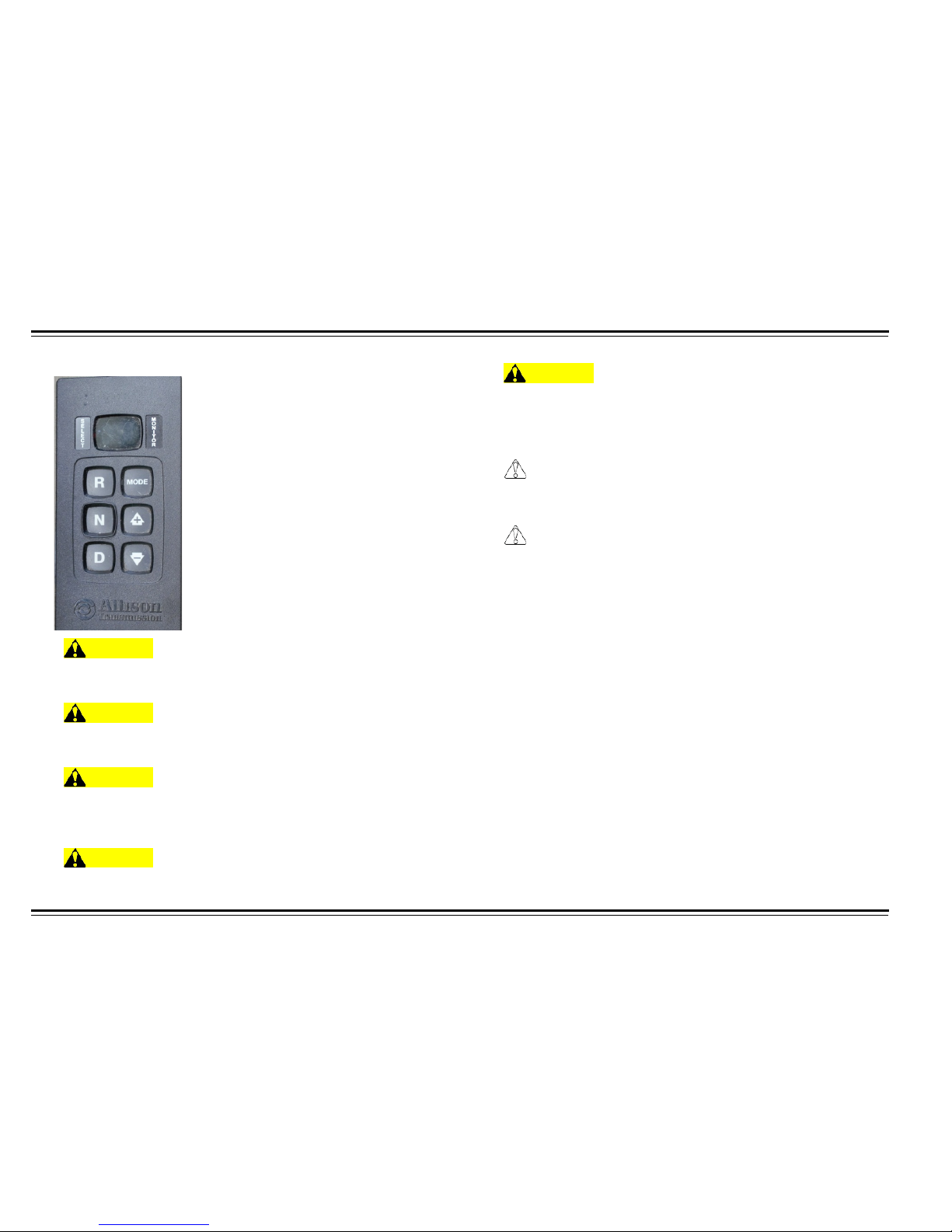
GEAR SELECTOR
WARNING
Before starting a vehicle always be seated in the driver's seat,
select N on the shift control, and set the parking brakes.
WARNING
If engine cranks in any gear other than neutral, service your
vehicle immediately!
WARNING
Before working on a vehicle, parking the vehicle , or leaving the
cab with the engine running, place the transmission in neutral, set
the parking brakes, and block the wheels.
WARNING
For safety reasons, always engage the service brakes prior to
selecting gear positions from neutral.
WARNING
It is a requirement that the driver of a commercial vehicle specified
under paragraph A sections 1-6 of FMCSA regulation 392.10 need
only cross railroad grade crossings in a gear that permits the
vehicle to complete the crossing without a change of gea rs.
CAUTION
Do not release the parking brake or attempt to select a gear until
the air pressure is at the correct level.
CAUTION
Battery (+) and (-) must be disconnected prior to any ty pe of
welding on any UltraShift™ equipped vehicle.
Gear selector lever has three positions operating panel.
•
R - Reverse. Selects reverse gear once vehicle is less than 2 Mph.
•
N - Neutral. Selects neutral.
•
D - Drive. Selects the default starting gear and automatically selects
gears between the starting gear and the top gear.
Page 40

35
CONTROLS
Start-up
1.
Turn the ignition key to ON and allow the “Allison shift pad” to powerup.
•
Engine cranking is delayed until the transmission power-up is
complete.
2.
Start the engine.
3.
Apply service brake.
•
If the service brake is not applied while selecting a starting gear, the
initial start gear will not be found and the driver will have to re-select
Neutral and press the brake while re-selecting the desired mode.
4.
Select the desired mode and starting gear on the shift console.
5.
Release the vehicle parking brakes.
6.
Release service brake and apply accelerator.
•
The transmission is not intended to provide hill-hold capability. The
service brakes should be used to stop and hold the vehicle on an
incline. To prevent the vehicle from rolling when starting on an
incline, place both feet on the brake pedal before sliding the right
foot to the throttle pedal. Gradually back off the brake while
applying as little throttle as necessary to move along the incline.
Power Down
1.
Select N on the shift control.
NOTE: Neutral should always be reached before UltraShift power down
is performed except in cases of emergency.
2.
Set the vehicle parking brakes.
3.
Turn off the ignition key and allow the engine to shut down.
Driving Tips
Proper Starting Gear
Choose a starting gear appropriate for the load and grade conditions
while at a stop in D mode by using the up/down buttons. Refer to D
mode for detailed information.
Page 41
CONTROLS
36
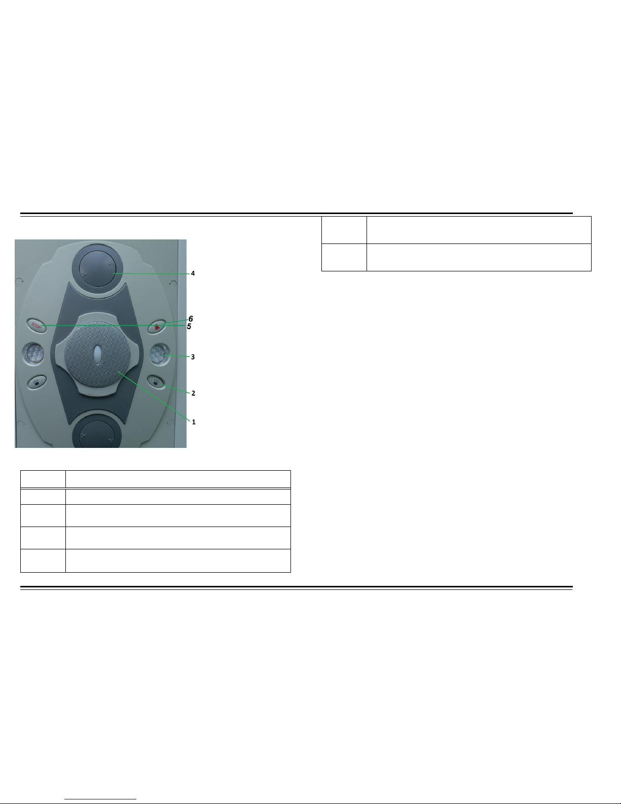
PASSENGER INTERIOR CONTROLS
Table 13: Passenger Controls
Number Item
1 Speaker
2
Individual Reading Lamp Switches
Push button to turn On/Off
3
Omni-directional Individual Reading Lamps
Push in any direction to direct light
4
Omni-directional Individual Ventilation Ports
Push in any direction to direct air flow
5
Stop Switch
Press to let the driver know to stop the vehicle
6
Passenger Chime Switch
Page 42

OPERATING
37
OPERATING
GENERAL INSTRUCTIONS
After performing the daily inspection and safety checks, you are ready
to operate the motor coach. Safety on the road also depends on you.
Observe weather and road conditions, then drive accordingly. Be
physically and mentally alert.
WARNING
Do not run engine for long periods of time in a closed or p oo rly
ventilated building, where exhaust gases can accumulate.
If, while driving the motor coach, any of the items below are noticed,
correct condition immediately.
•
STEERING ACTION - Binding, wander, shimmy, excessive steering
wheel play, and pulling to one side.
•
BRAKING ACTION - Increased pedal travel, slow response,
chatter, grabbing, weak, pulling to one side, and excessive air
pressure drop for brake application.
•
VIBRATION - From engine, driveline, accessories, and wheel
imbalance. Scan the instrument panel frequently and be alert for
any changes from normal gauge readings.
Refer to appropriate subject in troubleshooting section of this manual
for detailed data.
ENGINE STARTUP
Engage parking brake. Put the gearshift in the neutral position, making
sure that the rear compartment doors are closed (or engine is
prevented from starting). Insert the key into the ignition start switch and
turn clockwise to the start position. The engine should start within 30
seconds. If starting fails, wait 2 minutes for starter motor to cool down.
Repeat start procedure until the engine starts.
Do not run a cold engine at high rpm. Idling too fast during warm-up will
cause too rapid and uneven expansion, resulting in premature engine
wear. The rpm should be increased gradually after starting a cold
engine.
Do not operate the motorcoach at high rpm until the engine water
temperature reaches 158°F (70°C).
CAUTION
Damage may occur if engine idles for more than 10 minutes at low
rpm. Idling the engine too slowly does not allow suffici ent splash
lubrication of cylinder walls and may result in excessive wearing
of pistons and liners.
There must be a display of the oil pressure on the instrument panel
within 15 seconds after starting the engine, otherwise stop the engine
and correct problem immediately.
If the parking brake indicator on the instrument panel is illuminated, the
parking break is engaged.
Page 43

OPERATING
38
Engine
After starting the engine, but before operation, be sure the indicator
lights and gauges work. The braking system air pressure should read
at least 81 psi (490 kPa) or above. Coolant temperature should be 158°
F (70° C) or above, and the parking brake released. You can now
operate the motor coach in a safe manner.
Normal Driving Conditions
Ensure the following are within their acceptable limits.
•
Oil pressure should be within the range of 33 to 52 psi (227 to 358
kPa ).
•
Water temperature should be within the range of 176 to 200° F (79
to 94° C).
•
The indicator of the air pressure gauge should be within the green
range of 78 to 130 psi (538 to 896 kPa).
If you encounter any abnormal sounds or smells, stop and check the
motor coach. Avoid any abrupt acceleration or braking if possible. Avoid
engine over-speed.
Before Stopping Engine
CAUTION
Do not shut off the engine while vehicle is in motion. This will
cause eventual brake and immediate power steering failure.
A hot engine has a great deal of heat stored up in its iron mass. Let the
engine idle for no more than 10 minutes before shutting down the
engine.
This will allow circulating c o ola nt an d lu bric at ing oi l to c ar ry heat away
from cylinder head, val ves, pis tons, cylinder liners, and bear ings , th us
preventing warping of valve stems or distortion of other parts resulting
from uneven cooling.
NOTE: Refuel before final shutdown. The less air space in the fuel tank
means that there is less op por tun ity there will be for water to condense
in the tank.
Stopping The Engine
CAUTION
Do not shift into neutral until vehicle is stoppe d!
Perform the following procedures:
1.
Bring the motor coach to a complete stop using the service brakes.
2.
Shift transmission into neutral. The transmission should be set to
the neutral position before shutting off the engine to prevent an
error report display.
3.
Set parking brake by pulling out control knob.
4.
Allow the engine to cool below 194° F (90º C). Do so by letting the
engine idle no more than 10 minutes.
5.
Shut engine down by turning the ignition key to the ACC position.
The accessory position cuts off the fuel supply and shuts down the
engine.
Page 44
OPERATING
39
WINTER DRIVING TIPS
Perform the following winter driving tips for enhanced motor coach
performance needed during cold weather
•
Add long life coolant into the cooling system.
•
Check the fluid level, specific gravity, and voltage output of the
battery.
•
Use soft water in engine cooling system.
•
Do not operate the vehicle until the engine has had time to warm
up.
•
Do not operate if any malfunctions are present.
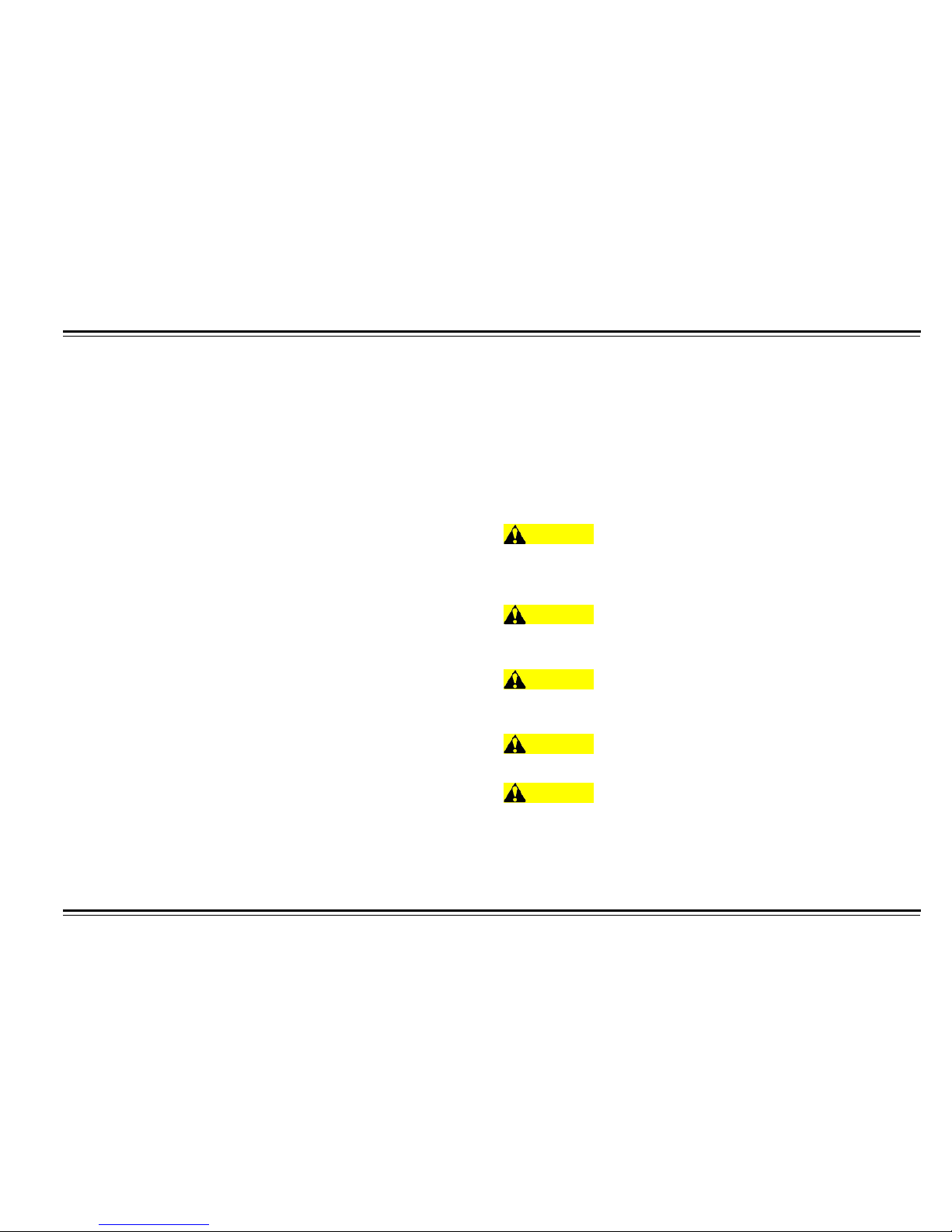
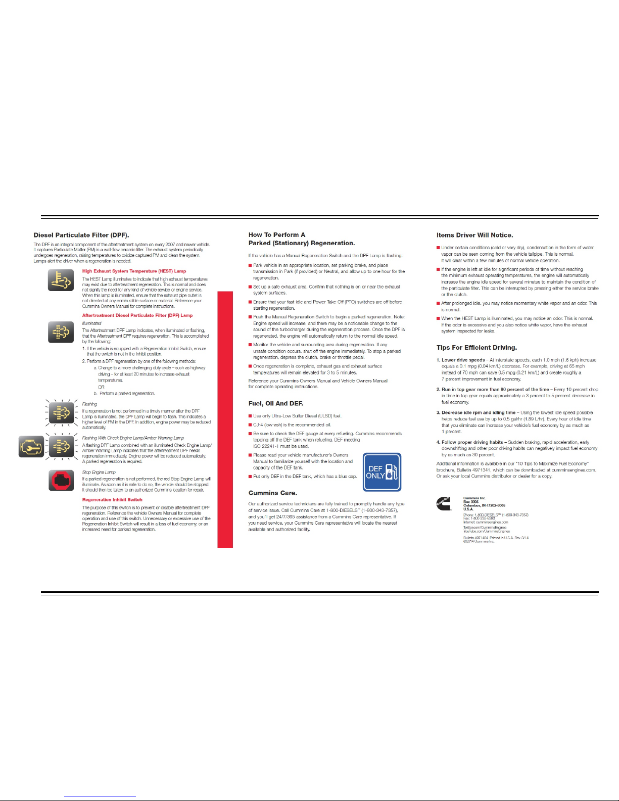
DPF REGENERATION
A diesel particulate filter, sometimes called a DPF, is a device designed
to remove diesel particulate matter or soot from the exhaust gas of a
diesel engine.
In addition to collecting th e particulate, a method exists to c lean the
filter. This is known as f il ter regeneration. Regener ation is the process
of removing the accumulated soot from the filter.
WARNING
To avoid serious personal injury or property damage, ensure that
no persons or objects are at or within 2 feet of the exhaust outlet
at any time during a regeneration.
WARNING
Ensure that exhaust and outlet are clear of any trash, grasses, or
other vegetation or debris.
WARNING
Use extreme caution during a stationary regeneration, as exhaust
gas tail pipe outlet temperatures can exceed 900° F (482° C).
WARNING
Stationary regenerations are to be performed outdoors only.
WARNING
DO NOT perform inside a garage or maintenance facility. DO NOT
attach an exhaust extraction hose to the exhaust outlet.
Page 45
OPERATING
40
Page 46
OPERATING
41
Page 47
OPERATING
42
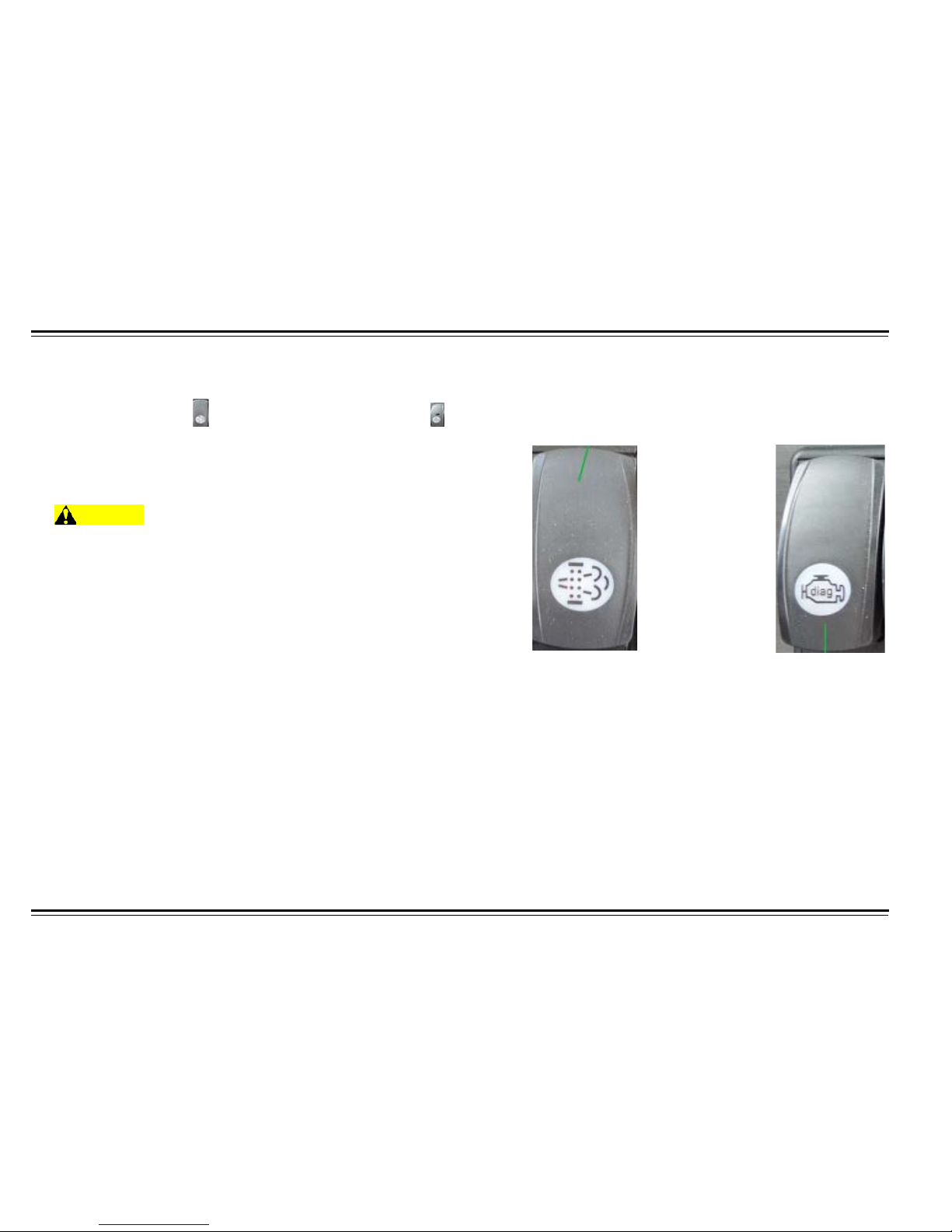
Park Regeneration Procedure
Park the vehicle safely off the road and away from flammable
materials. Place vehicle in neutral and apply parking brake.
Press regen button ON then press engine diagnosis button . DPF Switch Diagnosis Switch
The engine speed will automatically ramp up to a preset RPM
which indicates the regen cycle has started. When regen cycle is
complete engine speed(RPM) will return to normal operating status
and return regen button to OFF position.
WARNING
Failure to perform Parked Regeneration when the exhaust
filter indicator is ON will cause the engine to lose power and
eventually shutdown. When performing Parked Regeneration,
make certain the vehicle is safely off the roadway and away
from people or any flammable materials or structures, as the
regeneration process will result in elevated exhaust temperatures.
Failure to follow these instructions may result in a loss of engine
power, vehicle speed, and may cause an accident or fire resulting
in property damage, personal injury, or death.
Page 48
OPERATING
43
AUDIO/VISUAL SYSTEM
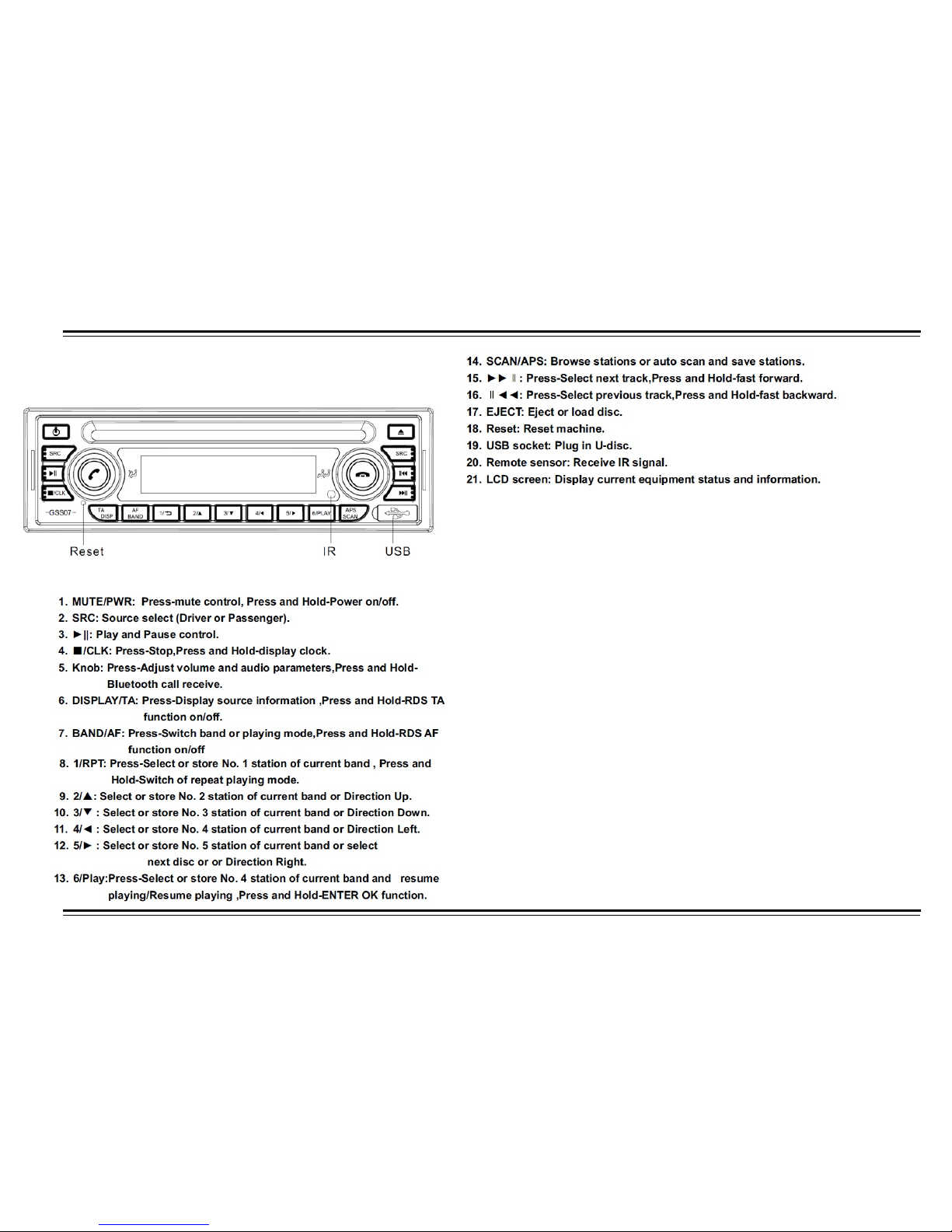
Xiahua™ DVD/CD
Table 1: Xiahua™ Audio/Video Player Basic Controls
GSS DVD/VCD/CD/MP3/USB Receiver features:
•
DVD/VCD/CD/MP3 Player
•
GIGA MP3 multi-play MP3
•
WMA
•
WAV Files Burned on DVD
•
MOS-FET Power Amp
•
iPod™ Ready
•
Satellite Radio Ready
•
Optional Bluetooth with KS-BTA200
•
DivX™ Compatible.
Microphone
The HT 45 audio system comes with a state of the art wireless
microphone. The microphone is located on motor coach next to
driver side seat with a convenient holder. In conjunction with public
address system, the wireless microphone will allow mobile
announcing. Microphone requires a 9V battery.
Page 49
OPERATING
44
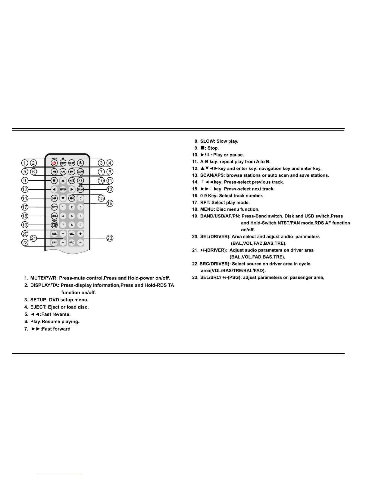
Remote Control
Operation
Page 50
45
OPERATING
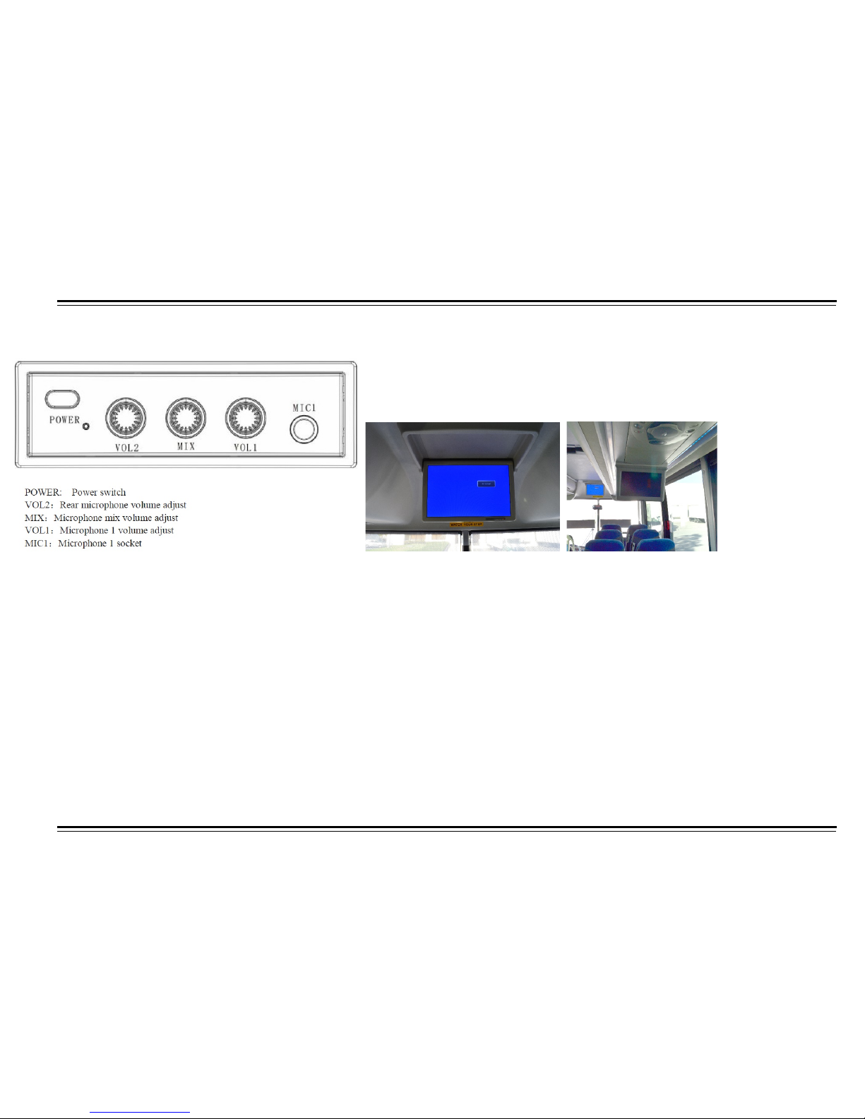
Public Address System
The coach is equipped with one 19 inches strategically drop down
LCD screen monitor that are controlled by switch at drivers dash and 6-10 inch
stationary LCD monitors .
Operation
1. 24V power supply, while output voltage is 13.8V±0.2V (8Amax). Use the host unit with audio amplifier and connect as to system requires, check
cable connection.
2. Press power butt on and it s tarts to work .
3. When the driver or guide speaks, plug the microphone to MIC1, turn on the microphone, the background sound is mute, only comes the sound from
the microphone, adjust knob VOL1 to adjust volume of microphone.
4. MIC2 socket on the backside of the unit, you can connect to microphone with long cable to install it on anywhere on coach, plug the microphone and
the background sound is mute, only comes the sound from the microphone, adjust knob VOL2 to adjust volume of microphone.
5. Adjust the mix knob in the middle, you can adjust the mix sound volume, no matter the host unit is in DVD, Cassette or radio status, you can speak
to microphone after it is plugged in, the volume will not be influenced by the host unit volume.
6. When playing karaoke VCD, or dual language VCD, press L/R key to mute the voice or select audio channel, this is only valid for VCD.
7. Goos eneck microphone and wireless microphone is optio na l.
Remark: Microphone mute function is optional.
Page 51
46
OPERATING
LAVATORY
General Information
For safety and convenience, the toilet module has been installed with
safety handles inside and out of the module.
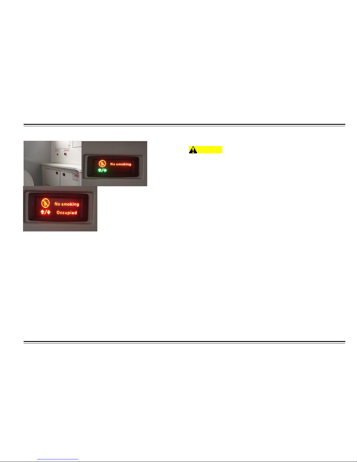
The dashboard contains an indicator for the following:
•
When The module is vacant or occupied.
•
For The status of the wastewater holding tank.
•
To alert the driver that the alarm button in the toilet module has
been activated.
•
Then The wastewater holding tank is full.
NOTE: If wastewater holding tank indicator is on, stop using toilet
immediately and ensure door is properly locked.
The toilet module door has a seal strip which prevents odors from
entering the motor coach. The toilet module is equipped with dual fans.
Low fan speed will vent constantly when the module is vacant. The fan
will change to high speed when the module is occupied. The outer fan
works to keep fresh air moving automatically.
The power to the toilet is controlled by the driver at the dashboard. If the
toilet is not functioning properly, the driver can turn off power and
temporarily put the toilet out of order.
NOTE: If the toilet is to be out of service for an extended time, turn off
the main power to the toilet.
Pre-Trip Procedures
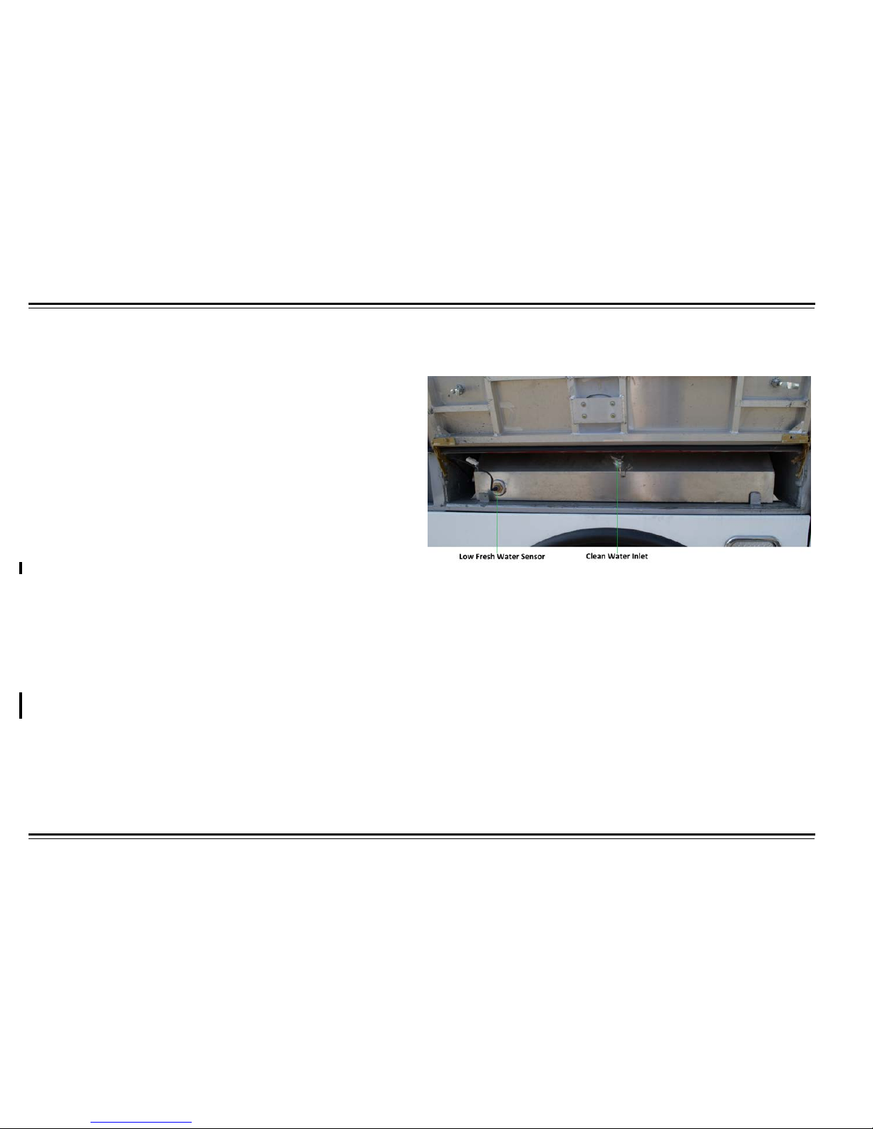
Ensure that the freshwater tank is full.
Fresh water tank for lavatory is located at the rear driver side
compartment on top of trailing axle. Fill freshwater tank by attaching
water hose and opening valve. Fill full and close fill valve. Fold wheel
skirt down and securely latch.
Check that wastewater tank is completely drained and drain valve
closed prior to trip. Make certain trash bin is empty prior to trip.
Check that toilet paper, paper towels, and other supplies are fully
stocked prior to trip. Toilet module needs to be cleaned and
maintenance regularly.
Page 52
47
OPERATING
Toilet Module Operation
Ensure the toilet system is functioning properly by locking the door. The
toilet has sensor inside and it turns on when toilet is in use. The
occupied light will make other passengers aware of the toilet status.
Toilet is unoccupied if the occupied light is off. If the toilet is occupied,
the occupied light will be on.
The dome light inside the toilet module has a dual status. The low light
level is on as long as the power to the module is on. The high light level
is on whenever a passenger enters the toilet module, closes, and locks
the door.
Sensor will automatically produce a flush that will go through the drain
valve into the wastewater holding tank.
Post Trip Procedures
After motor coach arrives at wastewater evacuation area, flip switch of
evacuation valve to drain holding tank.
WARNING
Do not spray water at the electrical junction box, fans, or other
electrical equipment. Doing so could damage equipment and
seriously injure personnel.
Remove all trash and restock supplies. Use a damp cloth to wipe the
surfaces. Sliding valve on holding tank should be cleaned regularl y to
ensure smooth operation.
Page 53
OPERATING
48
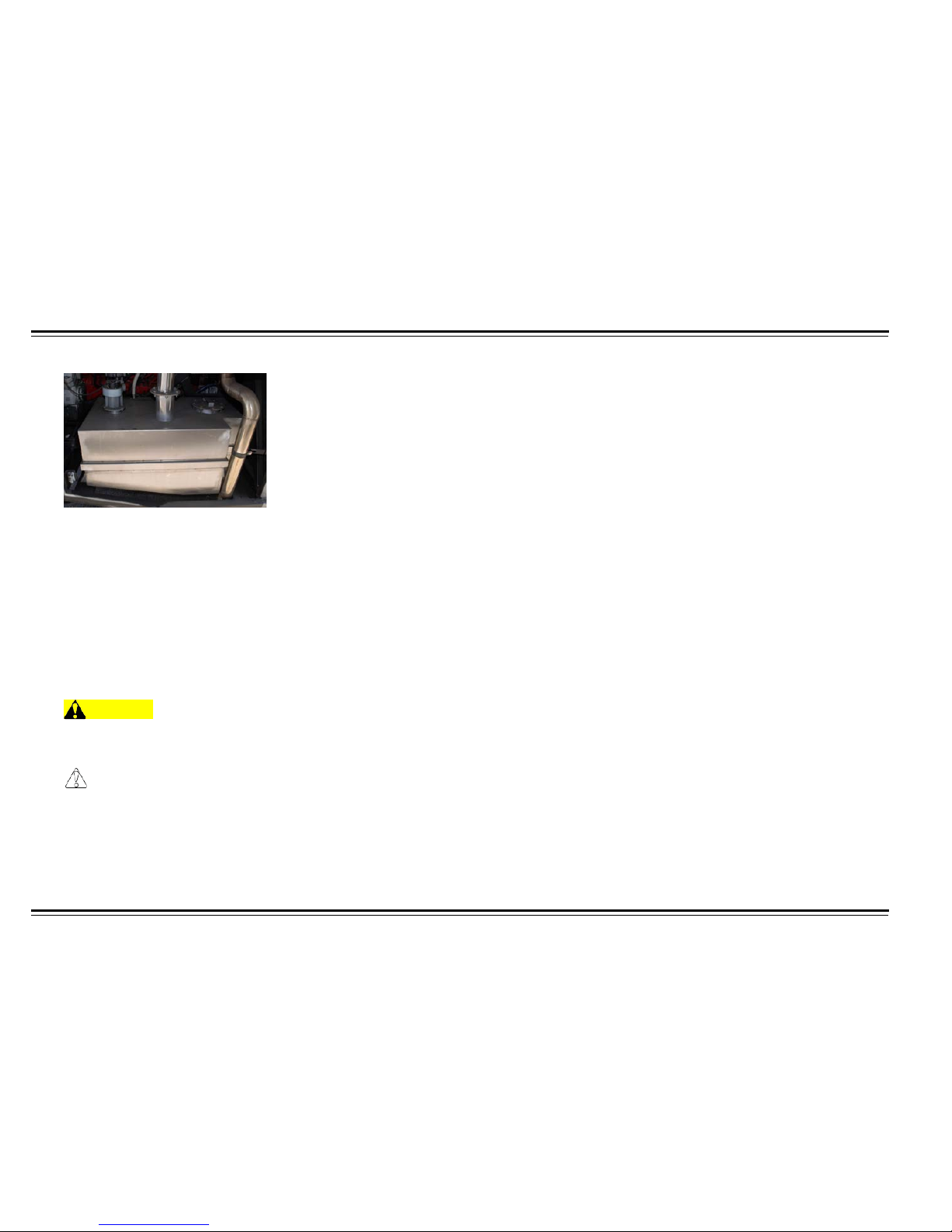
Wastewater Holding Tank
Wastewater holding tank is located in the right rear access panel of
the motor coach.
Flip switch back after evacuation.
When cleaning inside of toilet module, remove the cover of the floor
drain. The water then can be drained directly out of the motor
coach through the floor drain.
Water tank capacity: 38.3 gallons
WARNING
Refer to local health regulations for pr op er d isposal
procedures and equipment.
CAUTION
Do not throw bottles or cans in toilet module can resul t in over
flowing or damage.
Page 54
49
OPERATING
Cold Weather Procedures
Shut down toilet module for sub-freezing temperatures. Drain all water
from freshwater and wastewater holding tanks. Ensure toilet flushes
several times to drain water from bowl. Toilet module cannot be put
back in service until sliding valve and all components are thawed.
CAUTION
Never try to open a frozen valve by force. Use warm water to
defrost valve before use.
ELECTRIC DRIVER SUN SHADES
Sun shades have been installed at the left and right behind the
windshield. Each shade has its own control switch on the lo wer left
switch panel console.
CAUTION
Do not try to operate manually, this could cause gears to break.
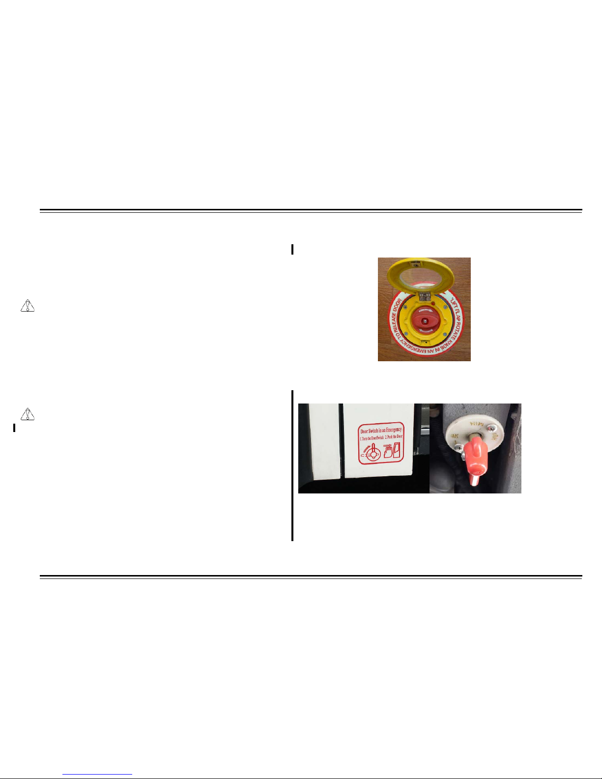
ENTRANCE DOOR EMERGENCY RELEASE
Interior Emergency Release
In case of emergency or door power failure, locate emergency release
knob in entry way. Rotate handle clockwise and push door outwards.
Exterior Emergency Release
In case of emergency or door power failure, locate emergency air dump
valve located on right side behind front bumper. Turn valve handle onequarter of a turn clockwise to release door. Two second delay will follow
before door opens. Once door is open, turn the interior emergency
release handle in entry way open before closing exterior emergency air
dump valve. Passenger door will now stay open.
Page 55
OPERATING
50
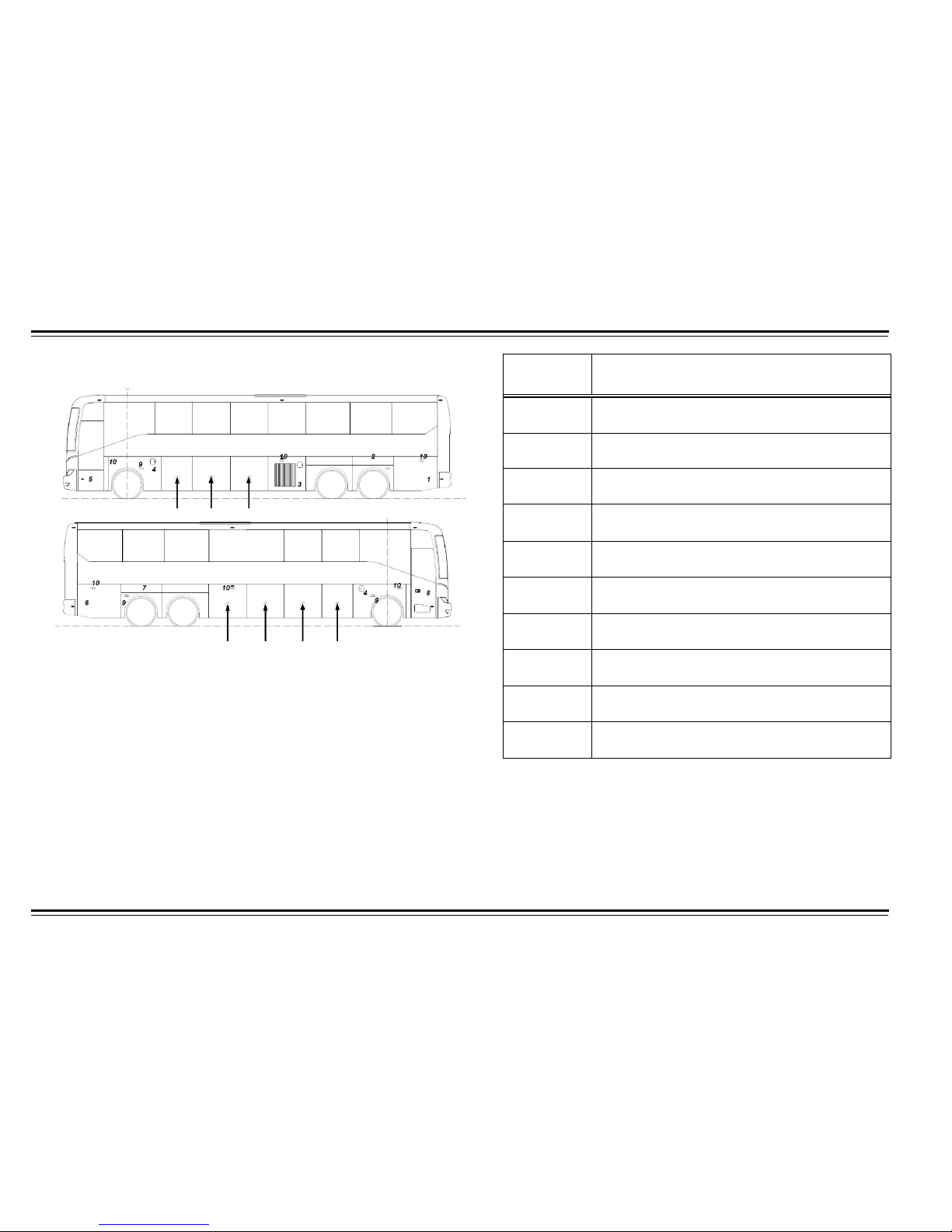
LUGGAGE COMPARTMENT
The transverse luggage compartment may be accessed through
seven aluminum doors. There are four luggage bay doors on curb
side and 3 luggage bay doors on street side. Each luggage bay has
an overhead light for safety and convenience. Luggage compartment
overhead lights are controlled by the switch on the driver’s right
switch panel.
The luggage compartment contains three emergency road reflectors
for roadside emergencies. The compartment also includes a tool kit
for minor repairs.
*Optional wheel chair lift information will be available upon
request
Number Item
1
Radiator Compartment
2
Fresh Water Compartment
3
A/C Condenser Compartment
4
Fuel Tank Filler Door
5
Junction Box Compartment
6
Rear Side Service Compartment/DEF
7
Battery Compartment
8
Entrance Door
9
Lights
10
Directional Lights
Page 56
51
OPERATING
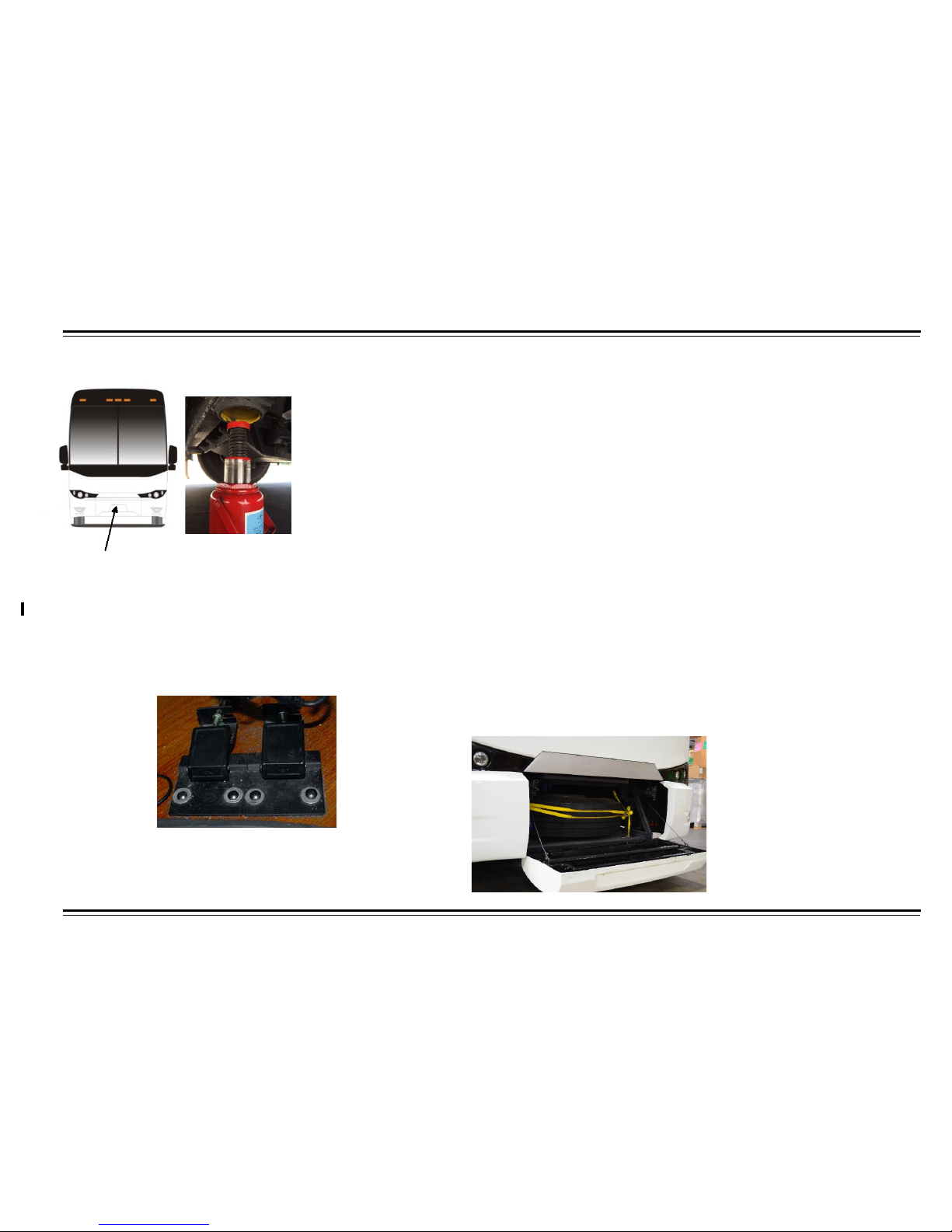
SPARE TIRE COMPARTMENT
Jacking points are located at front and rear
axles marked in yellow
The HT 45 has an easily accessible spare tire compartment located
behind the front motor coach body panel. The spare tire compartment
latch can be released by lifting both spare tire compartment release
handles.
The spare tire compartment release handles are located inside the
motor coach dash and behind an access panel. The access panel is on
the far-right side of dash. Push the two access panel release latches
and remove panel.
To remove the spare tire, perform the following:
1.
Fold bottom door completely down.
2.
Loosen ratchet straps, allowing excessive slack for strap to be placed
above tire as it is being removed.
3.
Pull the tire forward so it slides along the rollers, using caution as the
tire exits the support rollers.
To place the spare tire back, perform the following:
1.
Place tire flat on first roller.
2.
Lift straps over tire while lifting and pushing tire back into the
compartment.
3.
Pull down ratchet straps to tire tread face.
4.
Tighten ratchet straps against tire tread face.
5.
Close spare tire compartment doors, closing the bottom door firs
Page 57

INSPECTION
52
DAILY INSPECTIONS
To make sure your motor coach is ready for service, make the following
daily inspections.
NOTE: Inspection check sheet is available at the end of this section,
and can be copied for reuse.
WARNING
Before checking, park the motor coach on a flat roadway.
Before starting each day, check or inspect the following to ensure
trouble-free performance:
•
Make visual inspection of entire unit.
•
Check under motor coach for signs of leaks. If any are noted,
correct condition causing leaks.
•
Check all fluid levels on chassis: engine and transmission oil,
coolant level, power steering fluid, and all other oil and liquid
levels. Also check engine belts, hoses, and wiring for condition
and adjust as needed.
NOTE: For more details, read the following:
ENGINE OIL LEVEL
CAUTION
Do not overfill the crankcase. NEVER operate the engine if oil
quantity is below the add mark.
With the engine stopped, pull out the oil level dip stick and clean it with
a clean cloth. Insert the dipstick into the crankcase completely, then pull
it out again. The fluid level should be between the add and full marks. If
engine had been running recently, allow at least ten minutes for oil to
drain into crankcase. Use only recommended engine oil.
ENGINE OIL PRESSURE
The oil pressure will be high soon after cool-starting the motor coach; oil
temperature will be increasing, and engine rotat ion speed will be
normalizing. The oil pressure should be in the range of 33-55 psi. If the
indicator is low or does not register within 15 seconds, stop and check
oil level/condition and for any needed repair.
DRIVE BELTS AND BELT TENSION
Check condition and tension of the belts on the engine, fan, and
compressor. If any relaxation, tighten belts. If there is any belt damage is
present, replace belt.
Check for intersecting cracks on belts. Cracks are acceptable along the
width of the belt, but if these transversal cracks intersect with
longitudinal (belt length) cracks, replace belt. Also replace if the belt
shows extensive wear.
CAUTION
Over-tight or excessive slack in belt tension can be harmful to the
engine.
Page 58
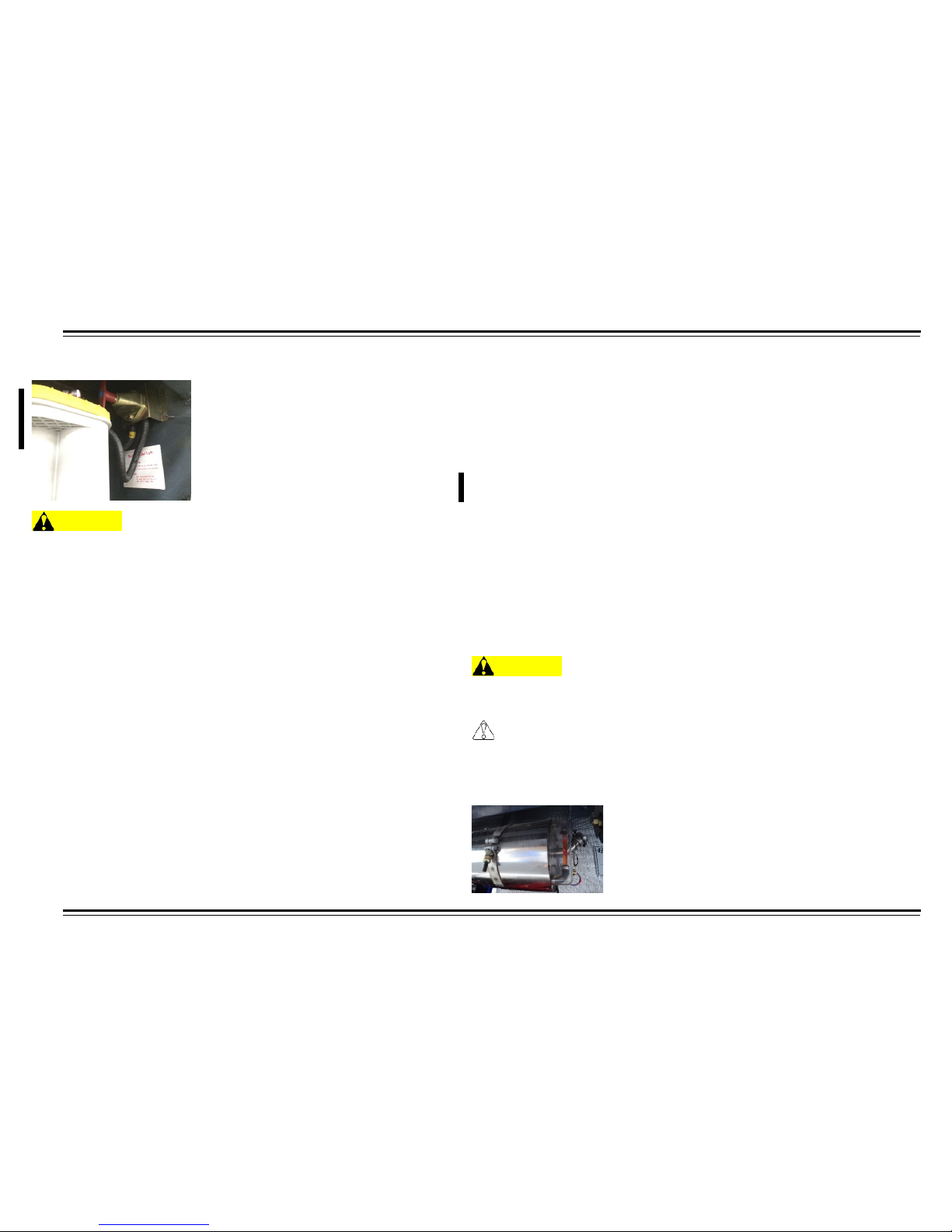
INSPECTION
53
BATTERY
WARNING
Do not start the engine when working on the batteries.
Check battery post and terminals for looseness, and the batteries
are acid free.
WASHER FLUID
Park on a flat, level surface. Open the outside hatch at left, front side of
motor coach where the washer fluid reservoir is located. Add washer
fluid if low.
NOTE: Washer fluid tank location may vary.
WINDSHIELD WIPER
Check that wiper arms and blades are secure, not damaged, and
operate smoothly.
AIR CLEANER
Wipe away the dust that may have accumulated over the air intake and
outlet once a weak. Check that all hose connections are tight to prevent
dust from being sucked into the intake system and reducing engine life.
NOTE: Replace air cleaner filter when air filter warning light ind icates .
AIR STORAGE TANK PURGE
Open (LH) driver axle skirt for rear tank drain valve access, and front
(LH) driver side access panel behind headlights for front air tank drain
valves.
If too much water is in the tank, check the dryer and pre-dryer for proper
operation and service if needed.
Air storage tanks are located on left side, inside the access panel and
behind wheel skirts.
NOTE: The core of the air dryer must be replaced at least once a year.
RADIATOR COOLANT
Check Radiator fan inlet for debris. Check fan blade condition.
WARNING
Scalding Hazard - Do Not Open Lid of Expansion Tank When
Engine Coolant Is Hot!
CAUTION
Check the coolant level only when the engine is off and coo l.
Add coolant when below full. Be sure to check coolant temperature
gauge.
Page 59
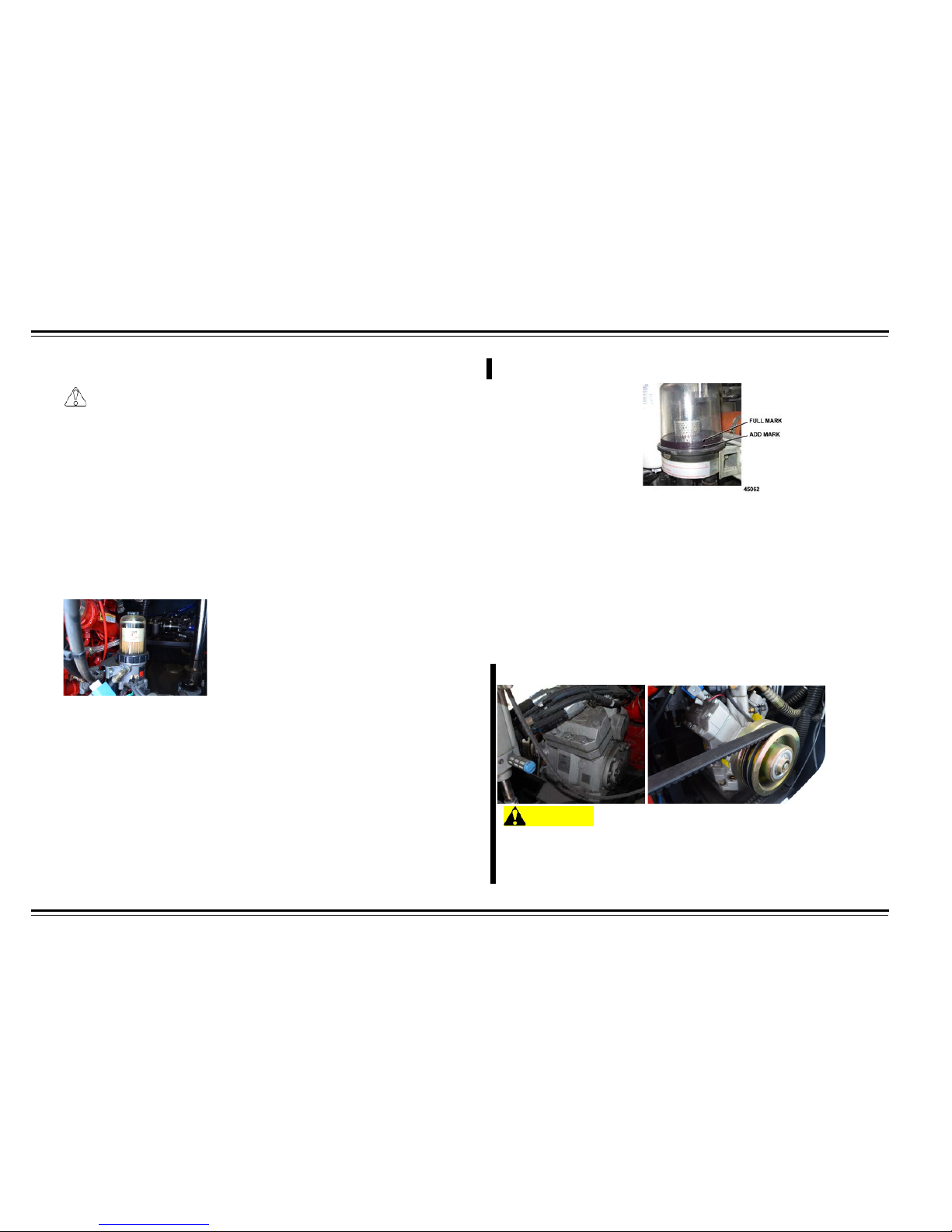
INSPECTION
54
FUEL TANK
CAUTION
Use recommended diesel only.
Check fuel gauge while ignition key is in “on” position or engine is
running. Add clean diesel when needed. If the motor coach operates
in a humid area, keep the fuel level full to prevent moisture on the
inside surface of the fuel tank. Ensure filters are clear of water
deposits.
Ensure there are no leaks in the fuel line and the fuel cap remains
tightly closed. Ensure fuel cap is clean before opening or closing.
PRIMARY FILTER-WATER SEPARATOR
Drain the primary filter-water separator system.
EXTERIOR LAMPS
Check that all external lights and reflective equipment are clean and
functional.
ELECTRICAL SYSTEM
Check functioning of all instruments and indicators, including
headlights, steering lamps, braking lamps, reversing lamps and
emergency blinkers.
NOTE: Clean instrument panel cover to ensure indicators can be seen
clearly.
POWER STEERING
With motor coach on level groun d, ope n the eng ine com par tment door
and inspect the oil level from the viewable window on the power
steering system reservoir. If low, add power steering fluid.
After adding power steering fluid, start the engine. The fluid will be
driven throughout the entire system and some air may be present. Turn
the steering wheel to the left and right limiting positions several times.
This will extract the air from the system. Shut down engine to allow air
to rise and escape the fluid in reservoir. Repeat bleed procedure if
needed.
BITZER COMPRESSOR
WARNING
Use extreme caution near compressor; hair, hands, or clothing
can be caught in drive belt. Serious injurie s are possible.
Check oil level on sight glass. Oil level should be one-fourth to threefourths the height of sight glass.
Page 60

INSPECTION
55
TIRES AND WHEELS
WARNING
Always maintain your tires in good condition. Frequently check
and maintain correct inflation pressures as specified by the tire
manufacturers. Inspect periodically for abnormal wear patterns
and replace/repair cut or broken tire casing. Always use
experienced, trained personnel with proper equipment an d
correct procedures to mount or remove tires. Failure to adhere
to these warnings could result in tire mal fun ction, damage to the
motor coach, personal injury, and possibly death.
NOTE: Correct inflation pressure should be:
•
Front axle 120 psi.
•
Drive axle 110 psi.
•
Tag axle 120 psi.
•
Spare 120 psi.
Check and maintain the correct inflation pressure for each tire every
morning or when tires are cool. Check tire pressures ONLY when the
tires are cool. Warm or hot tires cause pressure buildup. Do not deflate
a warm tire to specified pressure. Tire thumping during the walk around
inspection will tell you if a tire is deflated, but the only way to check tire
pressure is with an accurate gauge. If any tires are found to be
considerably under inflated, the motor coach should not be driven until
cause of the leak is determined and repairs have been made.
Regular and frequent inspection and proper care will give you the
assurance of safe, reliable tire operation. Most tire wear problems are
caused by under inflation such as a slow leak. Low pressure is a tire's
worst enemy. It allows tires to flex badly and this causes high
temperatures to build up. Heat causes early tire damage, such as flex
breaks, radial cracks, and ply separation. Furthermore, low tire
pressures can affect control of your motor coach, particularly at the
front wheels.
Look for bumps, blisters, cuts, punctures, cracks, uneven wearing, and
tread depth. Verify that lug nuts are tight. Adjust to specifications if
loose.
NOTE: After driving a new motor coach approximately 31 miles (50
Km), an adjustment of the lug nuts should be performed according to
torque specifications. The fastening sequence should be cross
symmetrical. The fastening sequence and torque specifications can be
found in the maintenance section.
*No regrooved tires on the front axle are allowed.
Page 61

INSPECTION
56
INSPECTION SHEET
Check engine oil level.
Check for fluid leaks. Engine oil, power steering,
transmission, axle oil, and coolant.
Check power steering fluid.
Check coolant system level.
Inspect drive belts.
Check belt tensions.
Check cooling fan.
Inspect coolant hose condition.
Inspect condenser fan inlet for debris.
Check transmission fluid level, if applicable.
Visually check battery.
Check washer fluid.
Check windshield wipers.
Check air cleaner restriction indicator.
Check fuel tank.
Check primary filter-water separator.
Check mirrors.
Check headlights (high and low beams).
Check taillights.
Check brake lights.
Check turn signals.
Check 4-way flashers.
Check clearance lights (red on rear, amber elsewhere).
Check red reflectors on rear and amber reflectors
elsewhere.
Check wheel nuts.
Check tire inflation.
Check tire condition.
Check A/C compressor oil level at sight glass.
Check that all compartment doors are shut tight.
Drain air tank.
Page 62

INSPECTION
57
Check that all equipment is secured.
Check steering system free play.
Check all emergency equipment.
Check driver’s and passenger seat belts.
Check horn.
Check foot and hand brakes (parking and emergency)
for proper operation.
Visually inspect motor coach ride height.
Check instrument lamps.
Check voltmeter reading with engine running.
Check brake air pressure.
Page 63

MAINTENANCE
58
MAINTENANCE
WARNING
To avoid property damage, personal injury, or dea th when
servicing the motor coach, park on a flat level surface, set the
parking brake, turn off the engine, and chock the wheels.
GENERAL INFORMATION
This manual contains information on systems operation, component
location, and periodic maintenance procedures which pertain to
standard and optional equipment on HT45 series motor coaches.
Proper maintenance is important to the safe and reliable operation of all
HT motor coaches. The service procedures described and/or
recommended in this manual are effective methods for performing
routine service or replacement of components. Other information,
which may be needed to supplement this manual, is contained in
separate parts of the operator’s manual.
Specific information about the engine and transmission can be found in
the applicable manufacturer’s service and troubleshoot ing m anua ls .
WARNING
Failure to perform proper maintenance and service could result in
property damage, personal injury, or death.
Your motor coach has been engineered and manufactured to provide
economical service. However, it is the responsibility of the owner to see
that the motor coach receives proper care and maintenance to assure
high performance.
WARNING
To avoid property damage, personal injury, or death; take care
when performing maintenance, making any inspections, or repair.
Some of the materials in this motor coach may also be hazar do u s
if used, serviced, or handled improperly. If you have any questions
pertaining to service, have the work done by a skilled technician.
Check the motor coach periodically as recommended by this Operators
Manual and by the component-specific Operation and Maintenance
manuals. Perform function checks as well as a test run after performing
maintenance.
Shorten maintenance intervals if motor coach use is severe or under
severe conditions. Keep all fluid reservoirs full and clean as needed.
Page 64

MAINTENANCE
59
MAINTENANCE RECORDS
It is the responsibil ity of t he owner to k eep acc urat e m aintena nce and
repair records; including receipts. Should the lack of required
maintenance be the reas on for repair, the warranty claim may not be
accepted.
CHTC (USA), INC. reserve the right to request your
maintenance and repair records for verification of compliance
with required maintenance practices and intervals.
CHTC (USA), INC recommends that the maintenance and
repair records/receipts be maintained as permanent records. All
records must state the date service was performed, mileage, vehicle
identification number, and service performed.
WARNING
Always use floor stands to support the motor coach before
working under it. Using only a jack c ould allow the motor coach to
fall, resulting in property damage, personal injury, or death.
WARNING
When welding on the motor coach is required, always disconnect
the ground battery terminal first. Then disconnect the positive
cable prior to electric welding. Attach the welder ground cable as
close to the part being welded as possible. If welding close to an
electronic component, temporarily remove tha t component.
Failure to follow this warning will result in a fire or explosion
hazard which could result in property damage, personal injury, or
death.
When servicing your motor coach always perform the following:
1.
Turn off the ignition switch unless the procedure calls for a running
engine.
2.
Set the parking brake and chock the wheels.
3.
Use support stands, never a jack, whenever you must be under a
raised vehicle.
4.
Do not smoke.
5.
Wear safety glasses for eye protection.
6.
Operate engine in a well-ventilated area.
7.
Do not work on brakes unless proper precautions are taken to avoid
inhaling friction material dust.
8.
Do not wear loose clothing, hanging jewelry, watches, or rings. Tie
up long hair and avoid rotating components.
9.
Avoid contact with hot surfaces. Allow hot components to cool
before working near or working on components.
10.
Correct any problems that were revealed during inspection, prior to
operating motor coach.
Page 65

MAINTENANCE
60
SEAT BELT MAINTENANCE
For safety, you should check the condition of your seat belts regularly.
Pull each belt out fully and look for frays, cuts, bur ns, a nd wear. Check
that the latches work smoothly and that the belts retract easily. Any belt
not in good condition or not working properly will not provide good
protection and should be replaced as soon as possible.
CLEANING MOTOR COACH
The coach body should always be kept clean. Wash the coach at the
end of every driving day. Do not use any type of harsh chemicals or
utensils to prevent damage to the body and paint.
•
Keep the seal strips of the doors and windows in good condition.
Inspect for damage and replace if needed.
•
Do not wash or rinse th e p aint ed s urf ac e of the bus with hot water,
alkaline water, kerosene or any type of oil. These types of products
could damage or ruin the paint.
•
Check the connecting portions between the chassis and the body
and repair any abnormal conditions that may be discovered.
•
Check the fasteners within the interior components of the coach
and tighten them as needed.
•
Check the condition of the passenger doors and make adjustments
as needed.
•
Check the lights and lamp conditions of the coach. If any damage is
discovered, replace it immediately.
Interior
Sweep or vacuum cabin daily. Clean up spills as soon as possible to
prevent injury and to prevent permanent stains. If necessary, hand
wash belts in warm water with neutral soap. Keep buckles dry! Rinse
thoroughly and allow to dry.
Exterior
Please clean your motor coach at approved washing sites. Do not wash
motor coach in direct sunlight. Use clean water to rinse motor coach
from top to bottom. Ensure that water does not pass through the air
filter into the engine. Do not spray water on the radiator grilles on the
right or left sides of the motor coach.
Wash the motor coach as needed. To remove light dust, wipe off with a
clean damp cotton towel or chamois. Always use a separate cloth or
sponge when washing the painted surfaces. The other areas, such as
steps, bumpers, and tread plate; could leave abrasive materials on the
cloth or sponge that could scratch the painted surfaces. Never use shop
rags.
Wash off all salts, highway deicers, petroleum, industrial fallout, and
chemicals as soon as possible. All exterior surfaces should be washed
(top, sides, and underbody).
To wash, use warm water and mild soap. Use caution when pressure
washing. Always use a wide fan, and care must be taken not to get too
close to the vehicle or any striping, lettering, labels, or vinyl overlay.
After washing, rinse the body thoroughly with water. Soap residues can
damage the finish.
Page 66
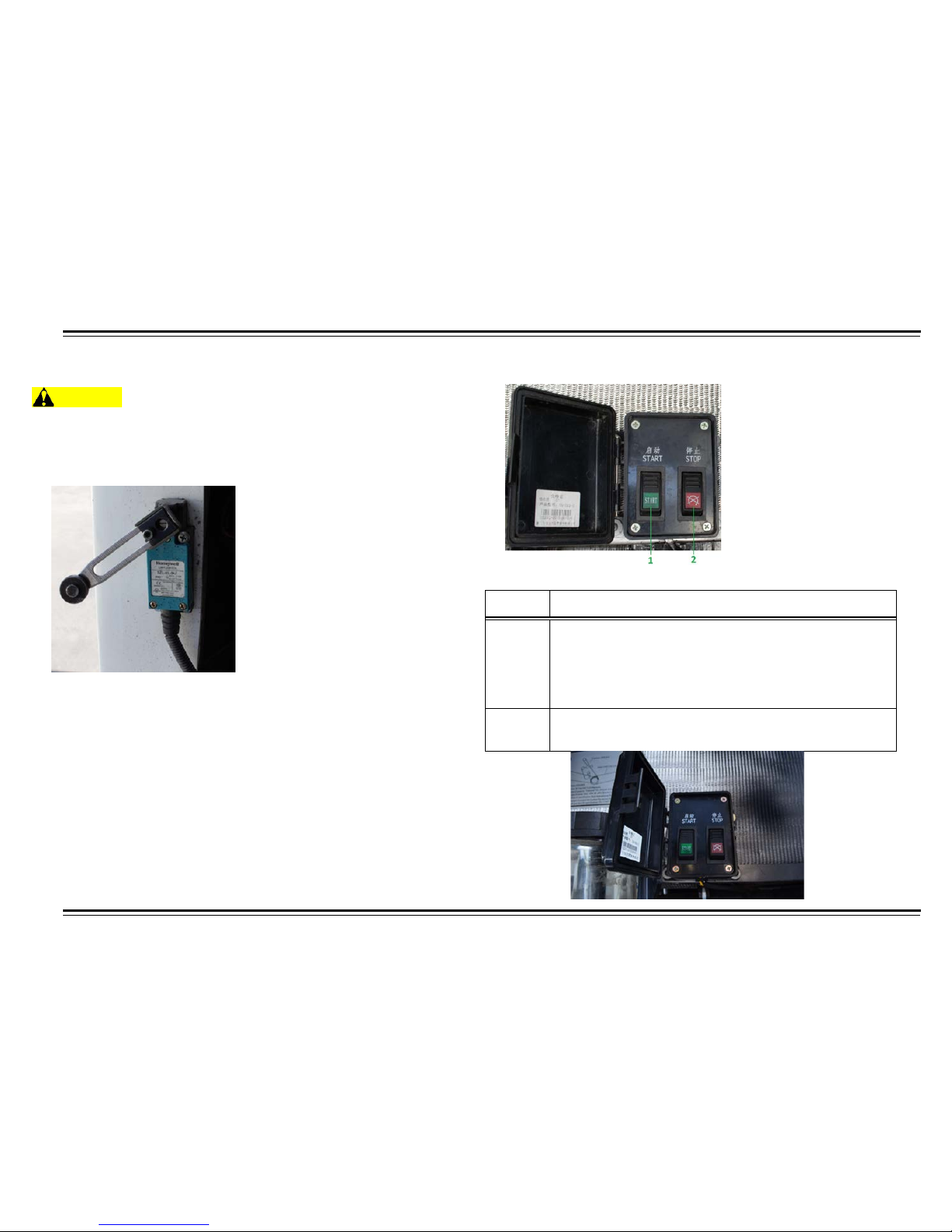
MAINTENANCE
61
Number Item
1
Remote Engine Start Button
Transmission must be in “N”, parking brake applied, and
ignition key must be in the “On” position to remote start
the engine. If area is safe, push start button to start
engine.
2
Remote Engine Stop Button
Push stop button to shut off engine.
ENGINE AND CHASSIS MAINTENANCE
WARNING
NOTE: Engine will not start while engine compartment access
panel is open. The engine access panel safety switch will disable
the ignition switch to prevent serious injury or death.
Engine access panel safety switch.
Clean engine and trans m ission ever y 10,000 m iles. Af ter ever y 50,000
miles, the following items of the intake manifold and the exhaust
manifold should be checked:
•
Check the nuts and bolts at various positions to determine if they
are loose. The torque should be even and uniform while fastening
the nuts and bolts. Otherwise, leakage may occur.
•
Check for cracks or holes on the intake manifold and the exhaust
manifold. If there is any damage or washout at the washers, replace
the parts as needed.
The main battery disconnect switch is located at rear curb side battery
Compartment shuts off all electrical supply. Turn handle right for power
Left to shut off.
REMOTE START SWITCH/MASTER DISCONNECT
Table 1: Remote Start and Master Disconnect Switches
Page 67
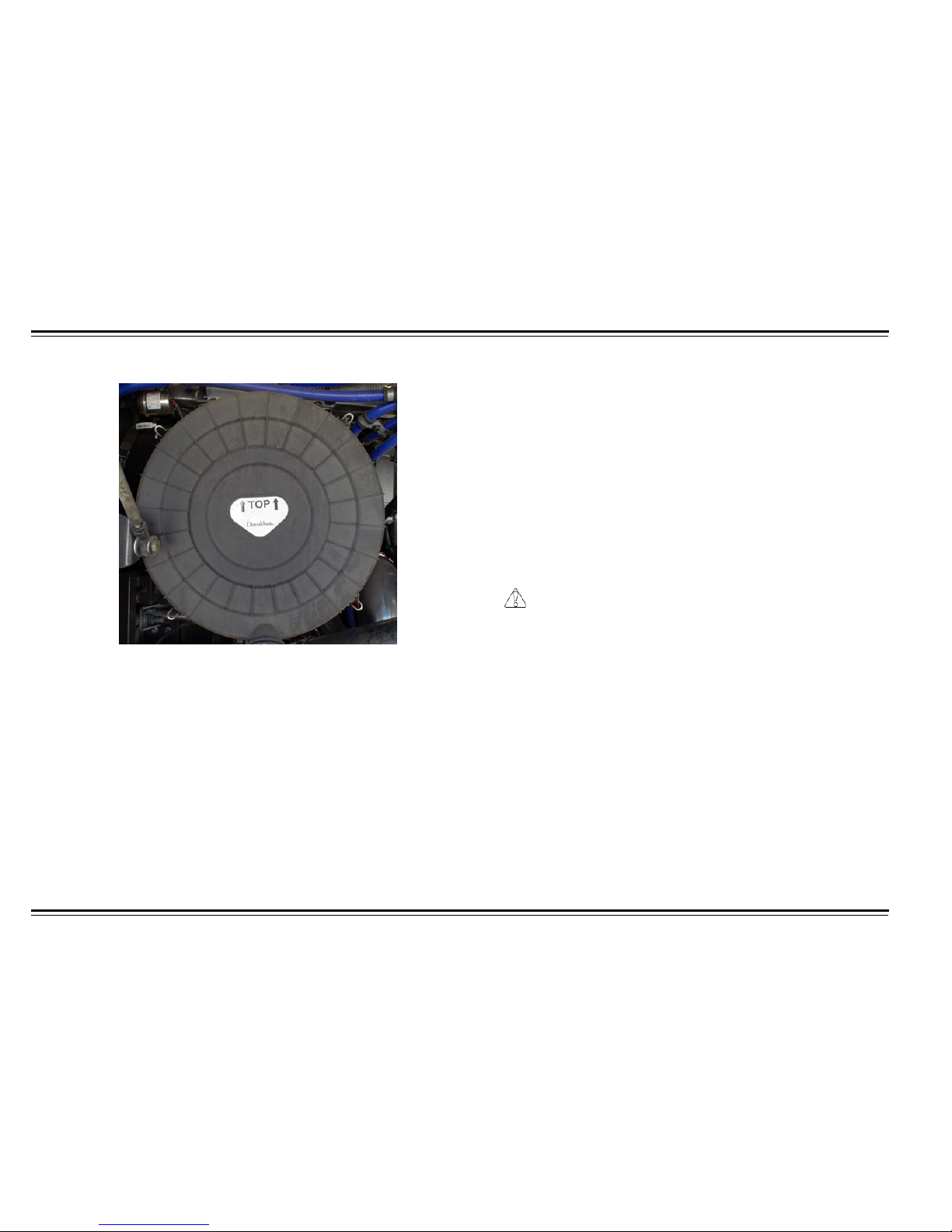
MAINTENANCE
62
AIR FILTER
NOTE: Replace the filter if damaged.
When the filter indicator lamp is activated on the instrument panel, it
means that the filter should be cleaned or replaced. A dirty filter will
cause insufficient power and wear of the engine. In order to ensure the
service life and normal operation of the engine, the air filter must be
maintained carefully and periodically.
The air filter should be checked and maintained after each 5,000-mile
increment. When the vehicle runs in a heavy dust environment, the
replacement cycle of the filter should be shortened. The engine must be
off when the intake system is being serviced. Do not start the engine
once the filter has been removed. Restart only after the filter has been
replaced.
To remove the cover, take off the 4 snap clips and remove the outer
filter and lid. Remove the dust in the unloading valve. Clean the filter by
tapping lightly with hand, wooden tool, or by blowing air into the filter
with an air compressor.
Remove the inner filter butterfly-nut. Clean th e filter by tapping l ightly
with hand, wooden tool, or by blowing air into the filter with an air
compressor.
CAUTION
Do not blow air on the outside surface of the filter core.
When using compress ed air, be sure the air pressure is lo wer than 7 2
psi (496 kPa). Blow the air from inside the filter to the outside, until the
dust is no longer visible.
Clean the surface using a clean, dry cloth. The filter should be checked
by using an examining lamp to make sure there is no damage before
installing it. Check for damage or cracks on the sealing ring.
NOTE: Do not start the engine without the air filter in place.
Page 68
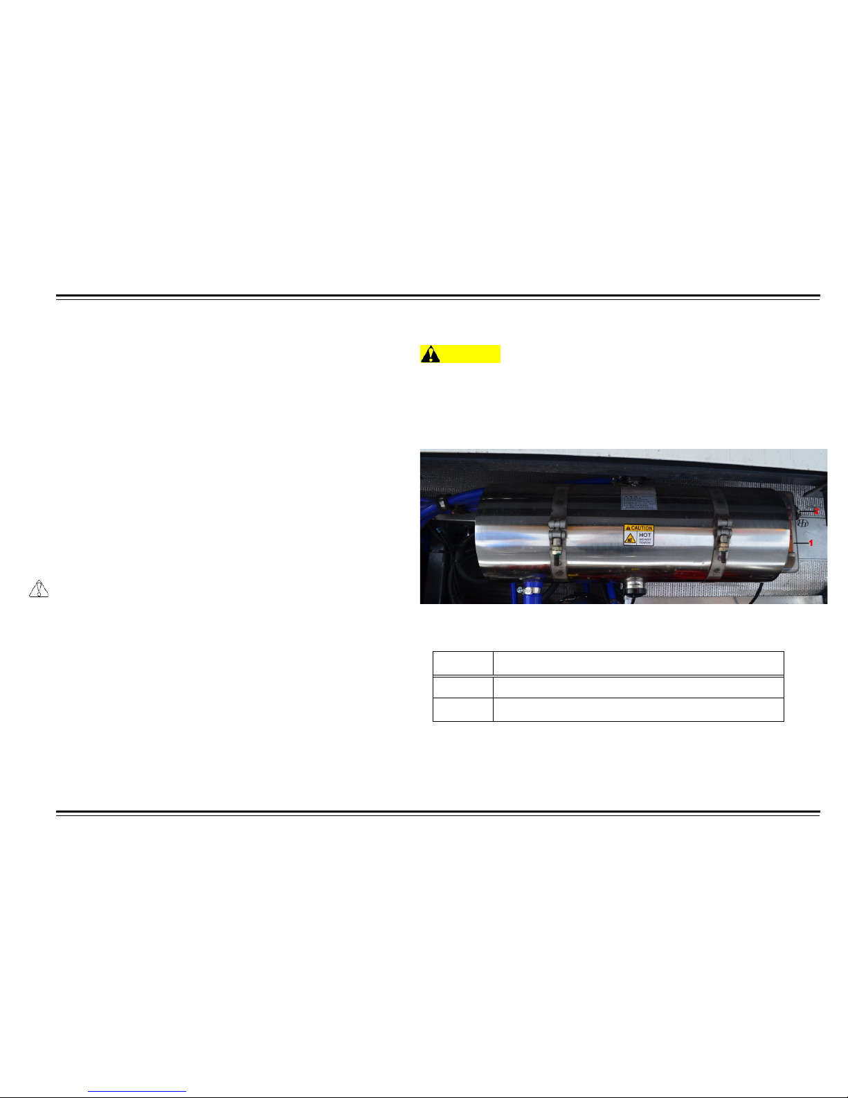
MAINTENANCE
63
Numbe
Item
1
Coolant Res er voir Le vel Window.
2
Coolant Reservoir Fill Cap.
RADIATOR
Keep the outside of the radi ator clea n by using compressed air or a
water hose. This will ensur e pr oper a ir cir c ulatio n an d c ooli ng of the
engine.
For the vehicles equipped with the inter-cooling device, keep the fins of
the radiator clean at all times. Normally compressed air or water is used
to clean the radiator. When there is hard scale on the radiator, steam
should be used. In order to avoid damaging the radiator fins, the flow of
air, water, or steam should be vertical to the surface of the radiator.
NOTE: It is essential to keep the radiator system clean and clear of any
obstructions, so the engine will cool adequately.
In areas, where there may be numerous flying insects, clean the
radiator fins more often.
CAUTION
Not abiding by this operating requirement could cause poor
engine cooling, and possibly severe damage to en gine
components.
ENGINE COOLANT
WARNING
Never open filler cap if coolant is hot. When opening filler cap, first
turn it carefully counterclockwise to the first stop and let the
pressure escape. Then turn it to the second stop and remove the
cap.
Coolant tank.
Table 2: Coolant Reservoir
Page 69

MAINTENANCE
64
Add the long-life anti-freeze and anti-rust liquid into the radiator. The
coolant is all-purpose and need not be charged/discharged in the
winter. When selecting the freezing point of the coolant, it should be 5
°
C lower than the minimum ambient temperature. Different types of
coolants should not be mixed.
NOTE: The coolant should be replaced every 2 years.
An antifreeze and a rust inhibitant solution (a mixture of the glycol and
water) should be added to the cooling system to prevent settling,
freezing, and oxidizing as well as to raise the boiling point.
CAUTION
Add the same type of coolant to prevent settling. If the coolant is
substandard or the freezing point is too high, replace it
immediately.
Long term operation of the engine may cause lime scale to build up in
the cooling system. Cooling system must be cleaned by the following
method:
•
Blend the causticity sodium of 24/28 oz. (700/800 gm) with
kerosene of 5.25 oz. (150 gm)
•
Pour the liquid mixture into the radiator.
•
Let the engine run for 5 to 10 minutes at a middle rate.
•
Let the engine rest for 10 to 12 hours.
•
Restart and run the engine for 10 to 15 minutes.
•
Drain the solution.
•
Once this is complete, flush the radiator with clean water.
Page 70
MAINTENANCE
65
Table 3: Coolant Mixture Chart
Temperature Maximum Boiling Point Glycol Content Water Content Additive Content
-49º F (-45º C) 226.4º F (108º C)
58% 32% 10%
-40º F (-40º C) 225.5º F (107.5º C)
54% 36% 10%
-31º F (-35º C)
224.6
º F (107º C)
50% 40% 10%
-22º F (-30º C) 223.7º F (106.5º C)
46% 44% 10%
-13º F (-25º C) 222.8º F (106º C)
42% 48% 10%
-4º F (-20º C) 221.9º F (105.5º C)
38% 52% 10%
5º F (-15º C) 221º F (105º C)
34% 56% 10%
14º F (-10º C) 220.1º F (104.5º C)
30% 60% 10%
Page 71
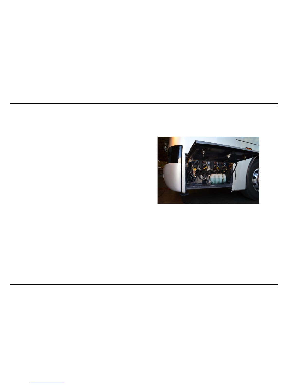
MAINTENANCE
66
BRAKE PEDAL
Adjust brake pedal clearance by loosening the locking nut of the brake
pedal and adjust the adjustable nut. Measure the vertical distance with a
steel strip ruler. The distance between the pedal free play position and the
position at which the pressing pressure wou ld dis tinc tl y incr ease sho ul d
be 0.32 to 0.48 in. (8 to 12 mm). Tighten the locking nut securely after
adjusting.
TIRE ROTATION
To extend the use and life of the tires, they should be rotated every
4,800 to 6,000 miles (8,000 to 10,000 km), depending on driving
conditions. If there is unusual or irregular wear, the tires should be
rotated immediately, as well as checking the orientation of the wheels
and the dynamic balance.
The rear axles wheel skirt can be easily lifted out of the way, allowing for
clear access to jack up the axles and wheel replacement.
•
To lift wheel skirt, pull on each bottom skirt corner to release skirt
from latch. Lift wheel skirt out of the way.
•
To reposition wheel skirt, pull skirt all the way down. Push on each
bottom skirt corner to secure into latch.
WINDSHIELD WASHER RESERVOIR
Maintain windshield washer reser vo ir level with a high qua lity washer
fluid. Washer reservoir is located in the first left access panel under the
driver’s window.
Page 72

67
MAINTENANCE
NEW MOTOR COACH BREAK-IN
CAUTION
The engine must not be run at its maximum output power during
the break-in period.
In order to maintain the excellent performance and efficiency of the
motor coach, as well as ensure an extended service life.
Pay attention to any unusual noises, vibrations, or handling
characteristics, at all times during break-in period. The mileage for the
break-in period is usually 1,500 miles (2,500 km).
New Motor Coach Preparations
It is advisable to perform the following procedures:
1.
Clean the motor coach.
2.
Check the connections and fasteners of various components.
3.
Check the coolant storage of the cooling system and look for
any leakage.
4.
Check the fluid levels in the engine, the gearbox, the driving
axle and the steering system. If fluids are low, add the
appropriate fluid being careful to not overfill.
5.
Check for any leakage in each system.
6.
Check to see if the brake system is normal and look for any
leakage among the valves and the various pipeline connections.
7.
Check the steering system for loose or blocking parts.
8.
Check tire pressure to ensure proper inflation
Page 73

MAINTENANCE
68
New Motor Coach Break-in Maintenance
Perform the following procedures.
NOTE: The vehicle should be driven on well-maintained roadways
during this period.
•
Drive the motor coach appropriately for a new vehicle and
accelerate smoothly. Do not place the motor coach in neutral when
coasting. As much as possibl e; do not brake in an urg ent manner
during the break-in period.
•
The speed limit during this time is less than 30 Mph. (50 Km/h).
Drive the bus empty for the first 150 miles (250 km). Do not
overload the bus after the 150 mile (250 km) break-in period.
•
Check the fluid levels in the engine, the gearbox, the driving axle,
and the steering system. If fluids are low, add the appropriate fluid,
but do not overfill. Check for any leakage in each system.
•
Check to see if the brake system is normal. Look for any leakage
among the valves and the various pipeline connections.
•
Check the steering system for loose or blocking parts
•
Check the electric appliances, lamps, and instruments.
•
Pay attention to the temperatures on the gearbox, the driving axle,
the wheel hubs, and the brake discs frequently. If there are any
overheating problems, find the cause and correct immediately.
•
Pay special attention to the oil pressure and engine coolant
temperature. They should remain in the normal range.
•
Replace the engine lubricant according to the engine
manufacturer’s manual. The engine lubricant should be drained
while the engine is hot.
WARNING
Take extreme precautions to drain engine oil while engine is hot.
The hot components or hot oil can cause severe burns which can
lead to permanent injury or death.
Post New Motor Coach Break-in Maintenance
Perform the following procedures.
•
Ensure proper nut and bolt torque on cylinder head, valve cover,
manifold bolts, etc.
•
Check the valve lash.
•
Replace the lubricant in the engine, the gearbox, and the reduction
final drive, as well as the filter core in the oil reservoir.
•
Check the connecting positions in the steering system for any
loosening or damage.
•
Tighten the bolts and nuts in the front and rear suspension systems
according to the specified torques.
•
Check the installation and fastening of the various components in
the hydraulic system of the steering mechanism. Lubricate and
maintain the motor coach according to this basic maintenance
check list.
•
Check for any oil, water, or air leakage within the various portions of
the motor coach.
Page 74
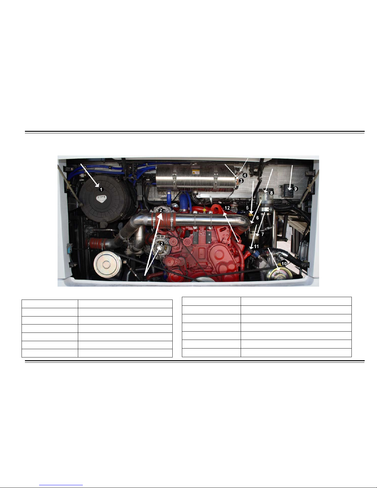
69
MAINTENANCE
ENGINE COMPARTMENT
Table 4: Engine Compartment Components
Number
Item 1 Air Filter
2
Alternator
3
Coolant Sight Glass
4
Coolant Fill Cap
5
Engine Oil Dipstick
6
Trans Oil Dipstick
Number
Item 7 Fuel/Water Separator
8
Power Steering Reservoir
9
Remote Start / Disconnect Switch
10
Bitzer AC Compressor
11
Engine Oil Fill Tube
12
Engine Plate
Page 75
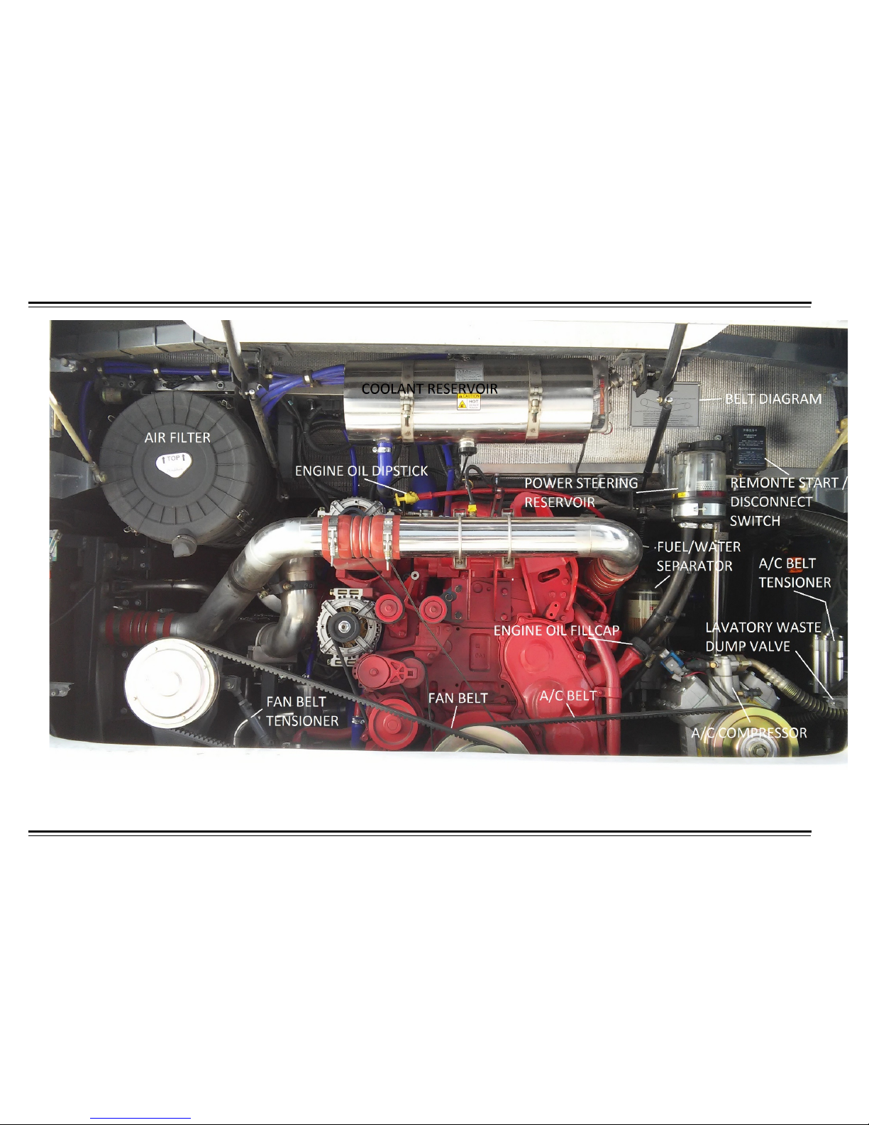
MAINTENANCE
70
Page 76
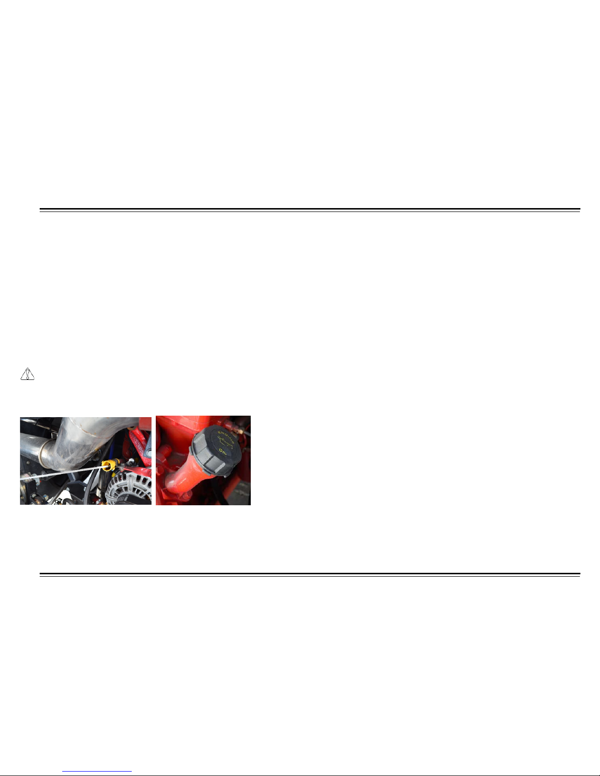
71
MAINTENANCE
ENGINE OIL
The preferred engine oil is an equivalent of the American Petroleum
Institute API CI-4 15W-40.
The engine oil will need to be replaced at specified intervals due to oil
consumption, contamination of the oil as it flows through the engine,
and the breakdown of chemical additives. The recommended
frequency for changing the oil is approximately every 15,000 to 20,000
miles (24,000 to 32,000 km). Based on the driving conditions, quality of
fuel and environmental conditions the frequency may increase or
decrease based on the individual use of each motor coach.
Engine Oil level
CAUTION
Never operate the engine with oil level below the ADD mark or
above the FULL mark on the dipstick.
Oil dipstick and oil filler tube.
Place motor coach on level surface. Pull out dipstick and wipe it clean
with a clean cloth. Insert dipstick and pull out again. The oil level should
be between the ADD and the FULL marks on the dipstick.
If the oil level is too low, add oil through the oil filler tube. Bring level up
to FULL mark.
Engine Oil Viscosity
Since the viscosit y of t he e ngine oi l c hanges with the tem per ature, th e
average ambient temperature at the operating site of the engine is very
important for us to choose oil viscosity grade. Occasionally, if
temperature drops below the lower limit, it may reduce the cold staring
capability of the engine but not cause any damage to the engine.
The engine oil with an excessively high viscosity would cause engine
starting difficultly. Therefore, the ambient temperature while the engine
starts is the main basis on which to choose an engine oil. You may also
avoid replacement of the engine oil due to the temperature changes
provided the multi-functional engine oil is used.
NOTE: Adding any additive into above-mentioned engine is
unnecessary. Avoid mixing and using different types of engine oil.
Performing oil changes on time is crucial.
Page 77
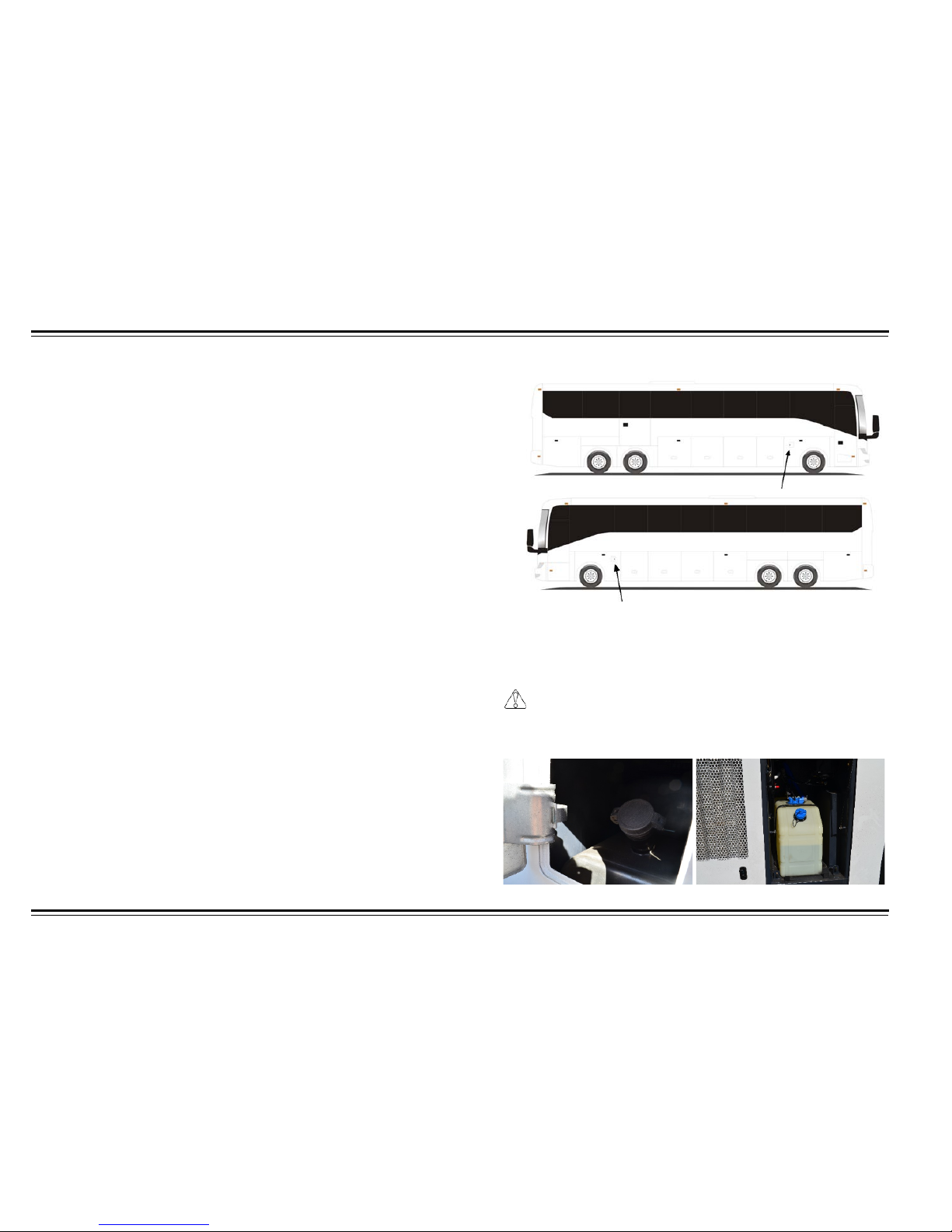
MAINTENANCE
72
GEAR LUBRICANT
Always use synthetic gear lubricant that conforms to the API GL5 SAE
80W-90 grade. Using the recommended brands from ZF Axles is
acceptable.
POWER STEERING LUBRICANT
Allison C-3, DEXRON-II hydraulic transmission oil should be chosen
when the power steering mechanism operates under temperatures
lower than 50
° F (10° C); If above 50° F (10° C) then choose C-3/10W;
the C-3/10W grade oil is an all-season oil in freezing zones; The C-3/30
grade oil is all-season oil in non-freezing areas.
FINAL DRIVE UNIT LUBRICANT
The lubricant for reduction final drive should meet the applied
conditions of the ECO FluidX (80w-90) grade of API for the heavy
load, the hyperbolic surface gear as well as meet the applied
ambient temperature conditions.
CHASSIS LUBRICANT
The #2 lithium-based lubricant grease (suitable for ambient temperature
of -22
° to 248°F (-30° to 120°C)) should be appl ied to the various
components.
DEF TANK
The DEF tank is located rear curbside access door panel. Filled to max
line. Max capacity 15 gallons. Never add diesel fuel into the DEF tank.
DIESEL FUEL
Fuel tank fill caps are located behind small locked panels. The small
locked panels are located on both sides of motor coach. Use only high
purity diesel, with a content of sulfur that is not more than 0.3 percent.
CAUTION
Avoid driving with an extremely low fuel level. Running extremely
low or out of fuel could cause engine damage.
Page 78
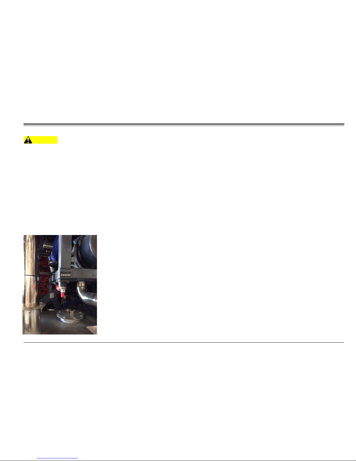
73
MAINTENANCE
EMERGENCY STARTING USING JUMPE R CABLES
WARNING
The following procedures must be performed exactly as outlined, otherwise a fire or a battery explosion could result in property damage,
personal injury, or death.
1.
Do not allow metal tools to contact positive terminal of battery to prevent shorting of the electrical system.
2.
Place transmission in Neutral and set parking brake in both vehicles.
3.
Shut off lights, heater, air conditioner and any other electrical loads in both vehicles.
4.
Wear eye protection.
5.
Make sure vehicle bodies are not touching.
6.
Connect one of the first jumper cables to the positive terminal of the dead battery and then other end to the positive terminal of the booster
battery.
7.
Connect one of the second jumper cables to the negative terminal of the booster battery and then other end to the chassis of the dead battery
vehicle.
8.
Reverse above procedure when removing the jumper cables.
Page 79
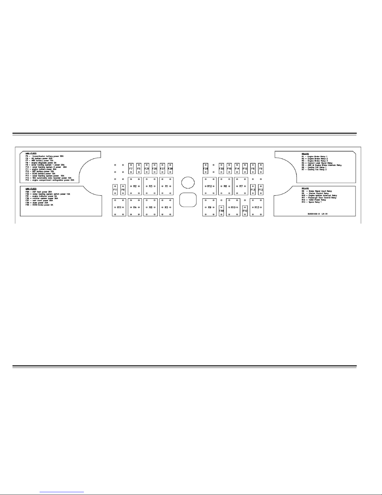
MAINTENANCE
74
FUSE PANEL
Page 80
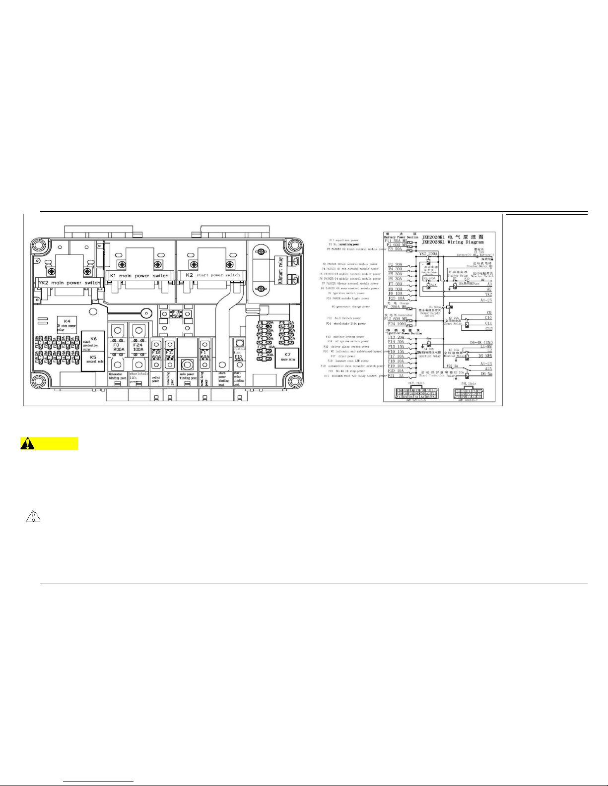
75
MAINTENANCE
First diagram’s fuse panel is installed in the luggage compartment, and second fuse panel is installed beside the battery cabin.
WARNING
Electrical circuits are designed with a particular wire gauge to meet the fuse and circuit breaker current rating. Do not
increase the size of fuse or circuit breaker, or change type of breaker supplied with your motor coach. To do so could
cause wiring to overheat and possibly burn, resulting in a fire which could cause property damage, personal injury or
death.
CAUTION
No modification should be made to any motor coach control system without first contacting your HT dealer.
Fuse panel can be found on wall at the rear of the luggage bay. Refer to the schematic located on the fuse panel cover.
Page 81

HT 45 MOTOR COACH
12851 South Reservoir Street
Chino, CA 91710
Tel.: (909) 325-8588
Fax: (909) 993-0838
Page 82

CHTC HT SERIES MOTOR COACH
OWNER LIMITED WARRANTY MANUAL
INTRODUCTION
The information provided in this manual has been prepared by the Warranty Department of
CHTC(USA), Inc. in order to assist you with any warranty questions or problems that may arise.
This manual describes many features of your motor coach and provides a guide to operating
procedures so that you can obtain the best performance possible.
Like all automotive equipment, your motor coach will require care and maintenance to retain its
maximum performance. This manual, along with the specific instructions provided by the leading
appliance manufacturers, is in your Owner’s Information Kit. The Chassis Operator’s Manual
outlines important areas of service and provides a maintenance schedule. Please follow them
carefully to ensure a safe, trouble-free service. Study these instructions carefully. A good
working knowledge of your unit and how to care for it will help you enjoy many miles and years
of use.
It is in the owner and operator’s best interests to review this document carefully and have a clear
knowledge of the coverage and terms and conditions of CHTC’s Limited Warranty before
submitting any claims. If you have any questions or problems in regards to the warranty coverage,
please contact the CHTC Technical Support Center at 1-800-216-6788.
WARRANTY REIMBURSEMENT LABOR RATE
Before your warranty account can be set up, CHTC requires that you submit your current
mechanical labor base rate for CHTC’s approval (and any changes in such rates that may occur
in the future). You should submit your CHTC service account number along with the labor base
rate to which credits are to be applied. In order for us to support your requested labor rate, please
provide related documents such as pay stubs, payroll statements, direct deposit statements, or
any other legal proof of your company’s labor cost for that category of employ ee. CHTC will make
reasonable efforts to ensure all information that you send to us remains confidential and will not
be used in any other manner except for approval of labor reimbursement. Please send the
requested information to:
CHTC BUS GROUP
12851 S. Reservoir St.
Chino, CA 91710
ATTN: Warranty Service Department
Fax: 909-993-0838
75
Page 83

Labor Rate is effective from the Approval Date by CHTC
CHTC’s Limited Warranty states that CHTC will credit to Buyer’s CHTC service account for the
labor cost on the removal and replacement of any defective part(s) that is covered by the
Limited Warranty based on:
(i) the number of hours determined by CHTC to complete the job
(ii) times 125% of the mechanical labor base rate* the Buyer paid at their locale garage at the
rate that’s previously approved by CHTC.
*mechanic labor base rate is the average base rate of labor paid to your local mechanics,
excluding any benefit costs or overhead expenses.
Example:
Top Mechanic’s rate: $35.00
Times:
Warranty reimbursement labor rate: $43.75
Third Party Repairs:
The payment at any third party facilities will solely be Buyer’s responsibility. Afterwards please
submit the applicable invoice(s) and any other required documentation to CHTC for review and
approval. Upon approval, CHTC will credit Buyer’s CHTC service account.
125%
LIMITED WARRANTY
Applicable only to HT Series Motorcoaches Manufactured by Jianxi Kama Bus
Co.
This Limited Warranty applies only to new coaches (together with all accessories and equipment
comprising such coach, collectively the “Coach”) manufactured and sold by CHTC for use in the
territorial limits of Canada and the United States, including Hawaii and Alaska, excluding Puerto
Rico, Guam and the Virgin Islands. This Limited Warranty is not assignable or otherwise
transferable to subsequent owners of the Coach unless CHTC receives either a properly
completed Sale Notification form or other documentation acceptable to CHTC.
Seller warrants for the Warranty Term herein specif ied that each new Coach, subject to certain
exceptions, exclusions, and conditions noted below, will be free from defects in material and
workmanship. This Limited Warranty applies only to de fects discovered during the Warranty Term,
which shall be 24 months or 250,000 miles whichever comes first, from the date of delivery of
the new Coach to Buyer.
The CHTC extended limited warranty applies only to contracts for future delivery of all new CHTC
HT Series motor coaches.
76
Page 84

Buyer shall give Seller written notice of any defect occurring during the Warranty Term to which
Buyer claims this Limited Warranty applies within thirty (30) days from the date such defect
becomes apparent, specifying the nature of the claimed defect and the date it became apparent.
Seller’s obligation under this Limited Warranty is limited to (A) repairing or, at Seller’s option,
replacing free of charge any parts that, in Seller’s reasonable opinion, have failed as a result of a
defect in material or workmanship occurring during the Warranty Term under normal service
conditions, provided that Buyer (i) has given Seller timely w ritten notice o f the de fect and (ii) upon
Seller’s request, has returned the defective part(s) to Seller, transportation charges collect; and
(B) crediting Buyer for the labor cost incurred in the removal and replacement of any such
defective part(s) based on (i) the number of hours designated by Seller to be required for such
work, times (ii) 125% of the base rate for mechanical labor prevailing at Buyer’s garage locale at
the time of replacement, such base rate to have been previously approved by Seller.
This Limited Warrant y Covers
Warrantor’s Limited Warranty covers only defects in the workmanship performed and/or materials
used to assemble those portions of your motor coach covered by the limited warranty. See also
the section “What the Warranty Does Not Cover” that is de tailed bel ow. “Defect” means the failure
of the workmanship performed and/or materials used to conform to Warrantor’s design and
manufacturing specification and tolerances.
EXAMPLES OF ITEMS NOT COVERED BY THE LIMITED W ARRANTY
● Engine (covered by Cummins, please see section “Engine and Transmission” below)
● Transmission (covered by Allison, please see section “Engine and Transmission” below)
● Tires
● Flood, collision, f ir e, theft, freezing, vandalism, riot, explosion, or object striking the
vehicle
● Par t s or equipment that failed as the result of normal wear and tear, or damage due to
accident, standard maintenance, or service adjustment.
● Road Service Calls and/or Towing charges (6 months and/or above $600 per
occurrence). Any assistance initiated by CHTC (roadside or otherwise) does not
constitute CHTC’s approval of, or agreement to pay, such charges
● Down time, rental of automobiles or other equipment, lodging, telephone, text messages,
or other intangibles
● Lost profits or revenues
● O vert im e, premium labor, or labor hours in excess of Standard Repair Time (SRT). SRT
must be used where applicable or labor breakdown must be provided to properly
process the request for warranty credits.
● Failure due t o improper installation or careless or negligent workmanship
77
Page 85

● Troubleshooting or diagnostic inspections (in excess of half an hour), phone calls for
technical support, or no trouble found/no repairs made.
● Ser vice items or routine maintenance items including, but not limited to: oil, oil filters, fuel
filters, air filter, tr a ns mission fluid, anti-freeze, coolant, belts, hoses, light bulbs, wiper
blades, tune-ups, fuel, windshields, brake and clutch linings, exterior mirror glass, wheel
studs, radius rod or king pin bushings, wheel balancing, wheel seals and bearings, and
drive axle pinion seals
● Shop supplies ( shop rags, drill bits, solvents and other miscellaneous items)
● Tools purchased to repair or replace parts
● Failures r esult ing from or due to the lack of required preventive maintenance, improper
repair procedures, or otherwise not complying with CHTC Maintenance manuals and
service bulletins.
● I ns t allation of non-OEM equipment
● Claims f iled after more than 30 days finding the defect
This warranty does not cover any economic loss, including without limitation, communication
expenses, meals, lodging, loss of use of the coach, loss of revenue, coach replacement charges,
towing, loss of time, inconvenience, cargo damage, overtime premium, mileage, shop supplies,
hotels or any other cost or expense resulting from a defect covered by this warranty.
Notwithstanding the foregoing, towing and/or road service is limited to $600 per incident when a
coach is inoperable or continued operation would result in additional component damage due to
a defective component listed in the engine component coverage list included therein. Towing
and/or road service charges due to a failure of a non-covered engine component or resulting from
an accident are not covered. Towing coverage is limited to a single tow per incident for covered
coaches that are accessible from a MAJOR paved highway and towed to the nearest authorized
CHTC Service Center.
● Perform maintenance on the vehicle as described in in the applicable maintenance
manual
● Perform routine adjustment services regularly, which includes but is not limited to: wheel
alignment, wheel balance, headlight adjustment, and brake adjustment
● Keep all preventive, maintenance, and repair records. CHTC will require these records
before performing any services.
OWNER’S RESPONSIBILITY
78
Page 86

ENGINE AND TRANSMISSIO N
The engine and transmission are warranted by their respective manufacturers (Cummins and
Allison) and NOT by CHTC. Since CHTC does not warrant the engine or transmission, the
preferred and suggested method is for you to request assistance from your local authorized
engine or transmission dealer and obtain engine or transmission service under any such
manufacturer’s warranty.
LEGAL REMEDIES
To the extent permitted by law, CHTC disclaims all implied warranties, including the implied
warranties of merchantability or fitness for a particular pur pose. To the extent such a disclaimer
is not enforceable, all implied warranties, including warranties of merchantability and fitness for a
particular purpose, are limited in duration to the duration of this limited warranty. The performance
of repairs is the exclusive remedy under this warranty. No person is authorized to modify this
warranty or to assume any other liability on behalf of CHTC unless this modification is made in
writing and signed by an authorized officer of CHTC. Some states do not allow limitations on how
long an implied warranty lasts, so the above limitation may not apply to you.
SUSPENSION OF LIMITED WARRANTY OBLIGATION
CHTC reserves the right to review and audit all warranty related records, including but not limited
to the claims filed, maintenance records, and parts returned. Also, CHTC has the right to suspend
its Limited Warranty obligations if Buyers are not following obligations, including but not limited to
putting Buyer's warranty account aside and withdrawing or revoking Buyer’s access to Technical
Support Center.
CONTACTING FOR ASSISTANCE OR REPORTING A FAILURE
When assistance is required related to warranty claims or other questions, please contact
CHTC Technical Support Center:
CHTC BUS GROUP
12851 S. Reservoir St.
Chino, CA 91710
1-800-216-6788
INFORMATION REQUIRED TO REPORT A F AILURE
● Operator and Buyer’s name
● Coach VI N Number
79
Page 87

● Coach Delivery Date (optional)
● O perator’s Fleet Number
● Mileage and Dat e at Failure
● Det ailed Descript ion of Failure (Complaint, Cause, and Correction Needed)
● Cont act Pers on, Address, Phone and Fax Numbers, E-mail (If applicable)
A warranty claim must be filed within 30 days after a failure has been reported and should be
processed through our Technical Support Center at 1-800-216-6788.
PERFORMING REPAIRS
As mentioned before, Based on this Limited Warranty, CHTC’s sole obligation is limited to:
repairing or replacing parts that failed as a result o f a de fect in material or workmanship occurring
during the Warranty Term under normal service conditions. Buyers have to provide CHTC with
timely written notice of the defect as well as return defective part(s) to CHTC, transportation
charges collect. Also, the labor cost incurred in the removal and replacement of any such de fective
part(s) based on working hours designated by CHTC, times 125% of the base rate for mechanical
labor at repair facility at the time of replacement, which have been previously approved by CHTC.
WARRANTY REPLACEMENT PARTS
Replacement part(s) may be available at CHTC Technical Support Center. Replacement part
orders for covered warranty claims go to CHTC Technical Support Center directly. Warranty
claims for defective parts should be filed and mailed to CHTC Technical Support Center. The filing
of a warranty claim is not contingent upon ordering a replacement part from CHTC. Instruction
will be provided when the warranty is filed. For example, the def ect ive par ts sh ould be returned
within 30 days (if instructed), otherwise CHTC will deny the warranty claim. After the part(s)
returned, CHTC will check if: (a) the part(s) is found not defective; or (b) the Buyer’s warranty
claim with respect to the returned part is not otherwise in accordance with the terms and
conditions of CHTC’s Limited War ranty ; or (c) the part was damaged during shipping (materials
must be well packaged in a sturdy container to prevent damage). If any of these conditions are
met, CHTC will deny the claim and return part(s) to Buyer with written explanation.
Parts purchased from CHTC Service Parts and used by Buyer on Coaches within the Coach
Limited Warranty will be handled, in case of failure, by the appropriate CHTC Warranty
Department. Warranty coverage for parts purchased and installed on a Buy er’s coach outside the
terms of the Limited Warranty will be covered only by the part’s warranty, if any, that may be
provided in connection with the part’s sale. Buyer should contact the appropriate Fleet Support
parts center for warranty claim handling instruction.
PARTS
80
Page 88

OTHER LIMITATIONS
The obligations of CHTC shall not extend beyond the obligations expressly undertaken herein
and CHTC shall have no liability of responsibility to the purchaser of the coach or any third party
for any loss or damage, whether direct or indirect or for incidental or consequential damage.
Some states do not allow the exclusion or limitation of incidental or consequential damages, so
the above limitation or exclusion may not apply to you.
THIS WARRANTY GIVES YOU SPECIFIC LEGAL RIGHTS AND YOU MAY ALSO HAVE
OTHER RIGHTS WHICH VARY FROM STATE TO STAT E.
81
 Loading...