

Page 1

SECTION PAGE
1
INTRODUCTION
2
THINGS TO KNOW BEFORE STARTING YOUR VEHICLE
3
UNDERSTANDING THE FEATURES OF YOUR VEHICLE
4
UNDERSTANDING YOUR INSTRUMENT PANEL
5
STARTING AND OPERATING
6
WHAT TO DO IN EMERGENCIES
7
MAINTAINING YOUR VEHICLE
8
MAINTENANCE SCHEDULES
9
IF YOU NEED CONSUMER ASSISTANCE
TABLE OF CONTENTS
.............................................................3
..............................9
..............................49
....................................71
..................................................95
..............................................131
...............................................141
..................................................199
.........................................215
1
2
3
4
5
6
7
8
9
10
INDEX
....................................................................225
10
Page 2

Page 3

CONTENTS
INTRODUCTION
1
m Introduction ...........................4
m How To Use This Manual ..................4
m Warnings And Cautions ...................6
m Vehicle Identification Number ...............6
m Vehicle Modifications / Alterations ...........7
Page 4

4 INTRODUCTION
INTRODUCTION
This manual has been prepared with the assistance of
service and engineering specialists to acquaint you with
the operation and maintenance of your new vehicle. It is
supplemented by a Warranty Information Booklet and
various customer oriented documents. You are urged to
read these publications carefully. Following the instructions and recommendations in this manual will help
assure safe and enjoyable operation of your vehicle.
NOTE: After you read the manual, it should be stored
in the vehicle for convenient reference and remain with
the vehicle when sold, so that the new owner will be
aware of all safety warnings.
When it comes to service, remember that your dealer
knows your vehicle best, has the factory-trained technicians and genuine Mopart parts, and is interested in
your satisfaction.
WARNING!
Engine exhaust, some of its constituents, and certain
vehicle components contain or emit chemicals
known to the State of California to cause cancer and
birth defects or other reproductiveharm. In addition,
certain fluids contained in vehicles and certain products of component wear contain or emit chemicals
known to the State of California to cause cancer and
birth defects or other reproductive harm.
HOW TO USE THIS MANUAL
Consult the table of contents to determine which section
contains the information you desire.
The detailed index, at the rear of this manual, contains a
complete listing of all subjects.
Consult the following table for a description of the
symbols that may be used on your vehicle or throughout
this owner’s manual:
Page 5
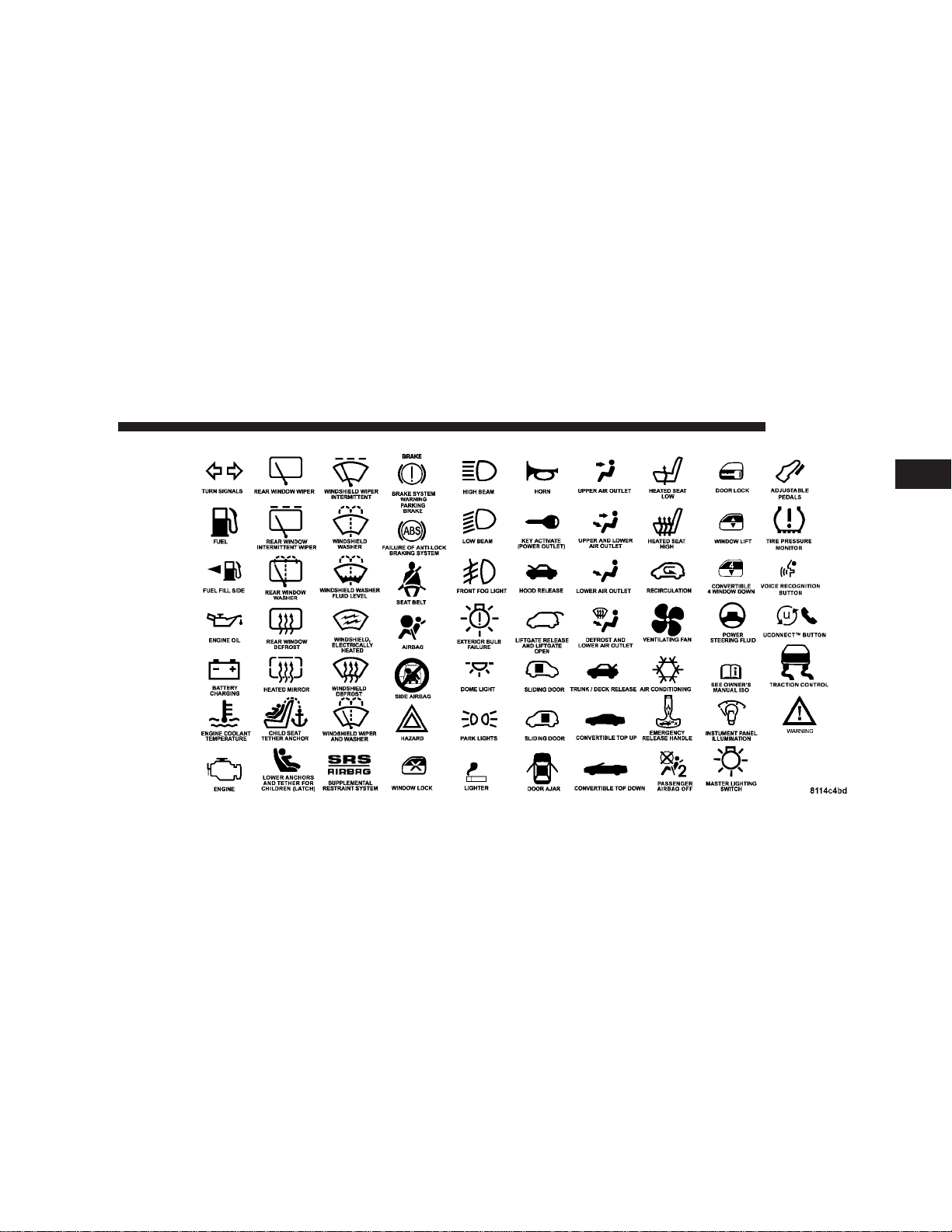
INTRODUCTION 5
1
Page 6
6 INTRODUCTION
WARNINGS AND CAUTIONS
This manual contains WARNINGS against operating
procedures which could result in an accident or bodily
injury. It also contains CAUTIONS against procedures
which could result in damage to your vehicle. If you do
not read this entire manual you may miss important
information. Observe all Warnings and Cautions.
VEHICLE IDENTIFICATION NUMBER
The vehicle identification number (VIN) is on a stamped
plate at the left front corner of the instrument panel,
visible through the windshield. This number also appears on the Automobile Information Disclosure Label
affixed to a window on your vehicle. Save this label as a
convenient record of your vehicle identification number
and optional equipment.
Page 7

VEHICLE MODIFICATIONS / ALTERATIONS
WARNING!
Any modifications or alterations to this vehicle
could seriously affect its roadworthiness and safety
and may lead to an accident resulting in serious
injury or death.
INTRODUCTION 7
1
Page 8

Page 9

THINGS TO KNOW BEFORE STARTING YOUR VEHICLE
CONTENTS
m A Word About Your Keys ..................11
▫ Ignition Key ..........................11
▫ Key-In-Ignition Reminder ................12
▫ Power Accessory Delay Feature ............13
m Door Locks ............................13
▫ Electronic Locking/Unlocking .............13
▫ Mechanical Release .....................14
▫ Automatic Door Locks ...................15
m Remote Keyless Entry .....................15
2
▫ To Unlock The Doors ...................16
▫ To Lock The Doors .....................17
▫ To Unlock The Trunk ....................17
▫ Panic Alarm ..........................17
▫ To Use The Panic Alarm .................17
▫ To Program Transmitters .................18
▫ General Information ....................18
▫ Transmitter Battery Service ...............19
m Vehicle Theft Alarm ......................19
Page 10

10 THINGS TO KNOW BEFORE STARTING YOUR VEHICLE
▫ To Arm The Vehicle Theft Alarm System ......20
▫ Entering The Trunk With The System Armed . . .21
▫ Security System Disarm ..................22
▫ Tamper Alert .........................23
m Windows .............................23
▫ Power Windows .......................23
▫ Auto Down Feature ....................24
▫ Power Accessory Delay Feature ............24
▫ Wind Buffeting ........................25
m Trunk Safety Warning.....................25
▫ Trunk Internal Emergency Release ..........25
m Occupant Restraints ......................26
▫ Lap/Shoulder Belts .....................27
▫ Enhanced Driver Seat Belt Reminder System
(BeltAlert™) ..........................30
▫ Six Point Belt System - If Equipped .........31
▫ Seat Belts And Pregnant Women ............32
▫ Seat Belt Extender ......................32
▫ Child Restraint ........................33
▫ Supplemental Restraint System (SRS) - Airbag . .38
m Engine Break-In Recommendations ...........46
m Safety Tips ............................47
▫ Exhaust Gas ..........................47
▫ Safety Checks You Should Make Inside The
Vehicle ..............................48
▫ Safety Checks You Should Make Outside The
Vehicle ..............................48
Page 11
THINGS TO KNOW BEFORE STARTING YOUR VEHICLE 11
A WORD ABOUT YOUR KEYS
The dealer that sold you your new Viperhas the key code
numbers for your vehicle locks. These numbers can be
used to order duplicate keys from your dealer or a
locksmith. Ask your dealer for these numbers and keep
them in a safe place.
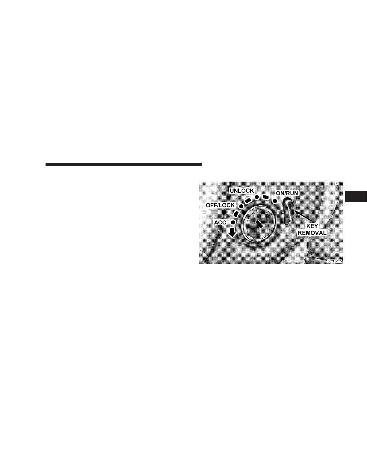
Ignition Key
2
Press clutch and insert the ignition key fully, then turn
the switch to one of the four illustrated positions. It may
be difficult to turn the key from the OFF/LOCK position
when starting your vehicle. Move the steering wheel left
and right while turning the key until it turns easily. To
start the vehicle fully apply the parking brake, press the
Page 12
12 THINGS TO KNOW BEFORE STARTING YOUR VEHICLE
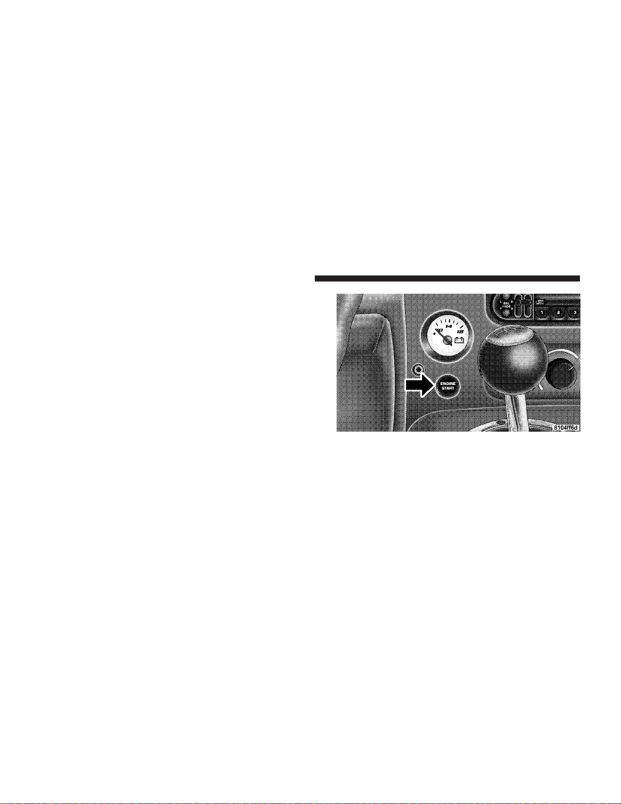
clutch pedal to the floor, place the gear selector in
NEUTRAL, move the key to the ON position, and press
the red ENGINE START button located on the instrument
panel. To remove the key from the ignition press the
clutch pedal to the floor, bring the vehicle to a stop, place
the gear selector in gear, and fully apply the parking
brake. Then turn the ignition key to the OFF/LOCK
position and push the release button behind the ignition
and pull the key out.
Key-In-Ignition Reminder
Opening the driver’s door when the key is in the ignition,
sounds a signal to remind you to remove the key.
Page 13

THINGS TO KNOW BEFORE STARTING YOUR VEHICLE 13
Power Accessory Delay Feature
The Power Accessory Delay feature provides the customer with the ability to operate the power windows,
and the radio for 2 minutes after the ignition switch is
turned off. If the key is removed from the ignition and the
driver door is opened prior to the completion of the
2–minute timer, the feature is immediately cancelled. The
Power Accessory Delay feature is initially enabled, but
may be enabled or disabled at the dealership.
DOOR LOCKS
WARNING!
Do not touch the exhaust pipe sill covers when
entering or exiting your Viper. They can be hot
enough to burn you. Observe the warning labels on
each door closure panel.
Electronic Locking/Unlocking
This vehicle is equipped with a virtual lock system. If the
vehicle is virtually locked, then the Outside door handle
is ignored. There is a door lock/unlock switch on each
door trim panel. Press this switch to lock or unlock the
door. The Odometer displays DOOR UNLOCKED continuously when both doors are unlocked. Also, the door
is considered unlocked if the inside door handle is
pulled. If only one door is unlocked, then the Odometer
will flash DOOR UNLOCKED every 2 seconds. After
about 40 seconds with the ignition off, the display will
turn off.
2
Page 14
14 THINGS TO KNOW BEFORE STARTING YOUR VEHICLE
NOTE: If you attempt to lock the doors with the key in
the ignition and the driver’s door open, the doors will not
lock.
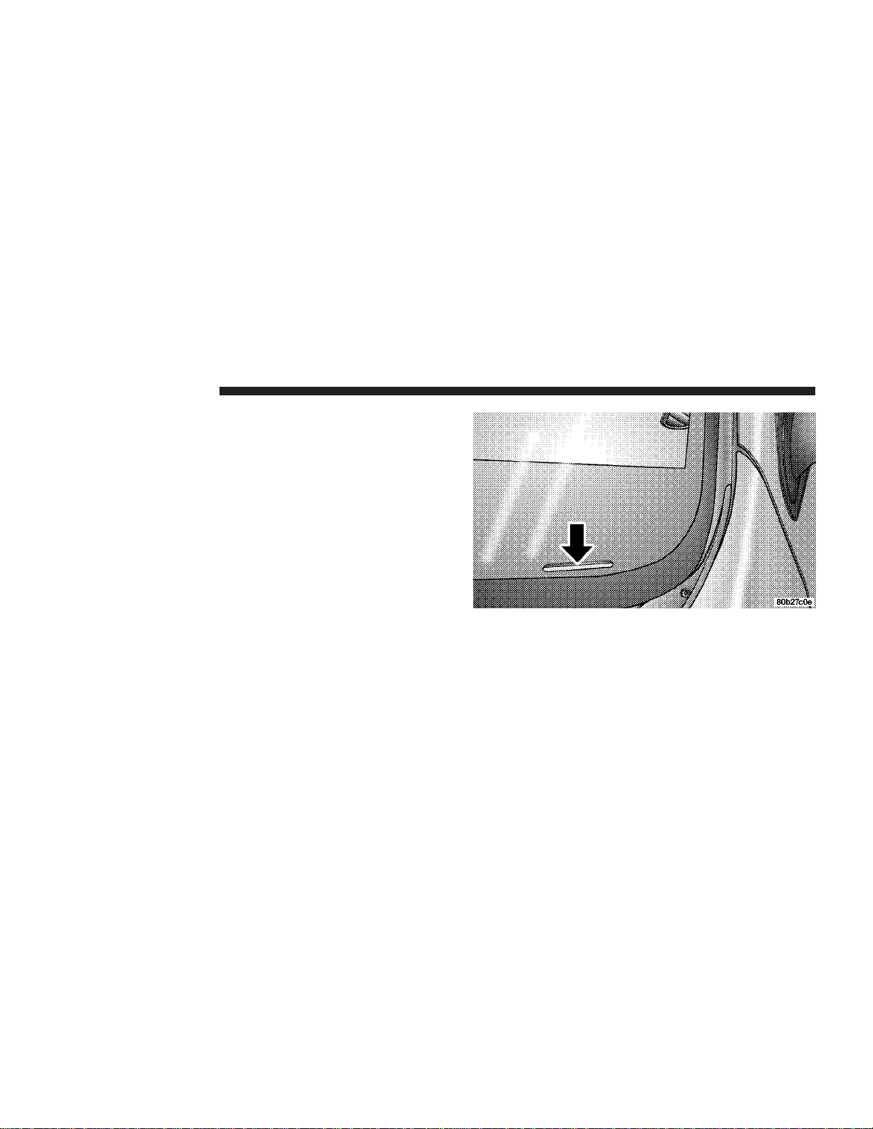
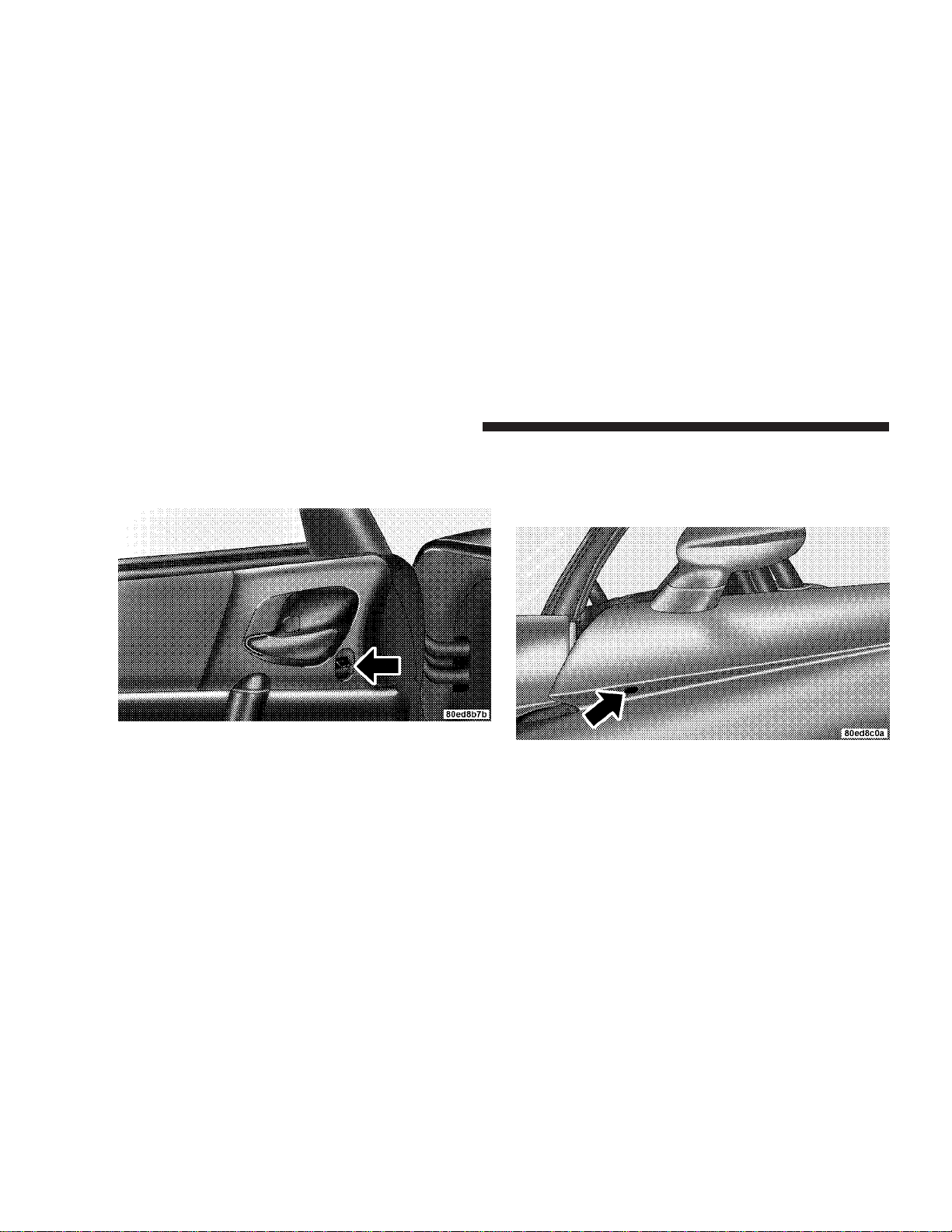
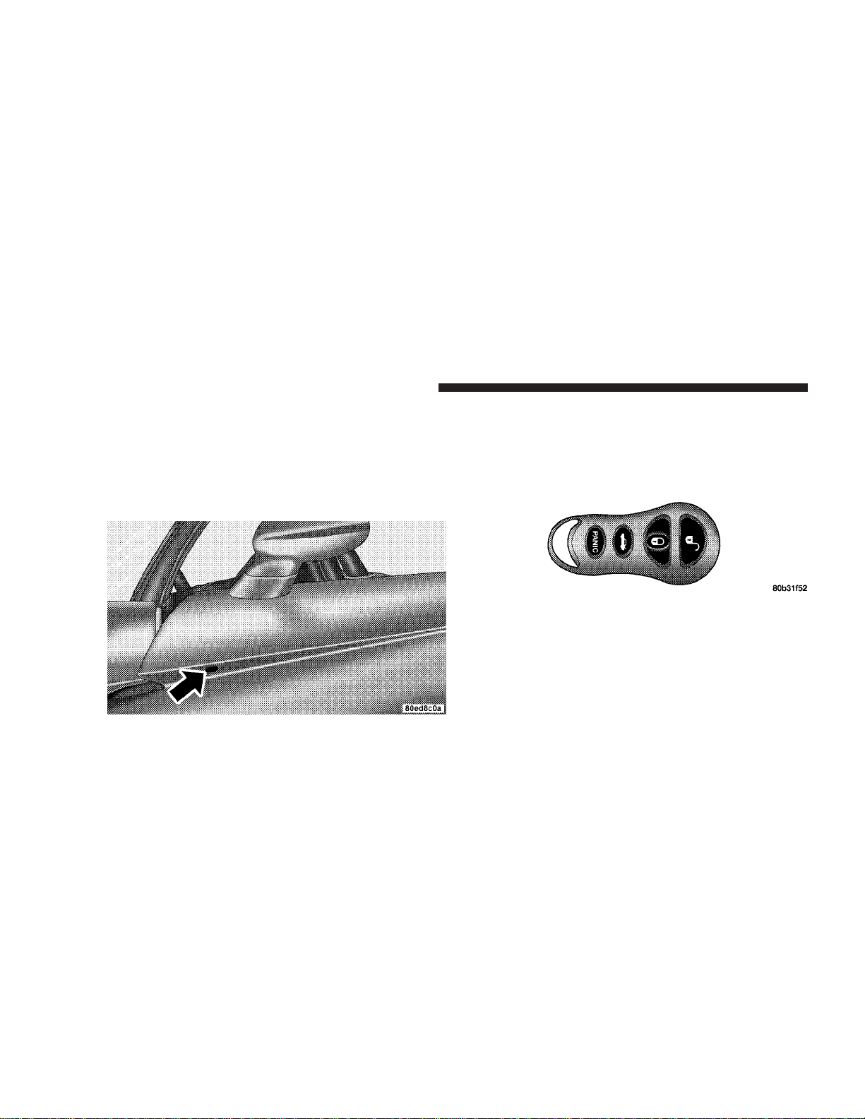
Mechanical Release
The driver’s door can be opened mechanically by inserting your key into the lock located on the underside of the
door panel, beneath the outside mirror.
Page 15
THINGS TO KNOW BEFORE STARTING YOUR VEHICLE 15
Automatic Door Locks
The doors will lock automatically from outside the vehicle when vehicle speed reaches 18 miles per hour with
the ignition On and the DOOR UNLOCKED displayed in
the odometer will disappear.
NOTE: If the vehicle is moving faster than 5 MPH, the
inside and outside door handles are ignored. This does
not overide the mechanical cable on the inside door
handle.
Automatic lock can be enabled or disabled by performing
the following procedure:
1. Close all doors and place the key in the ignition.
2. Cycle the ignition switch between ON/RUN and OFF
4 times ending up in the OFF position.
3. Depress the power door lock switch to lock the doors.
4. A single chime will indicate the completion of the
programming and that the feature was toggled ON/OFF.
This feature can also be disabled at the dealership if
desired.
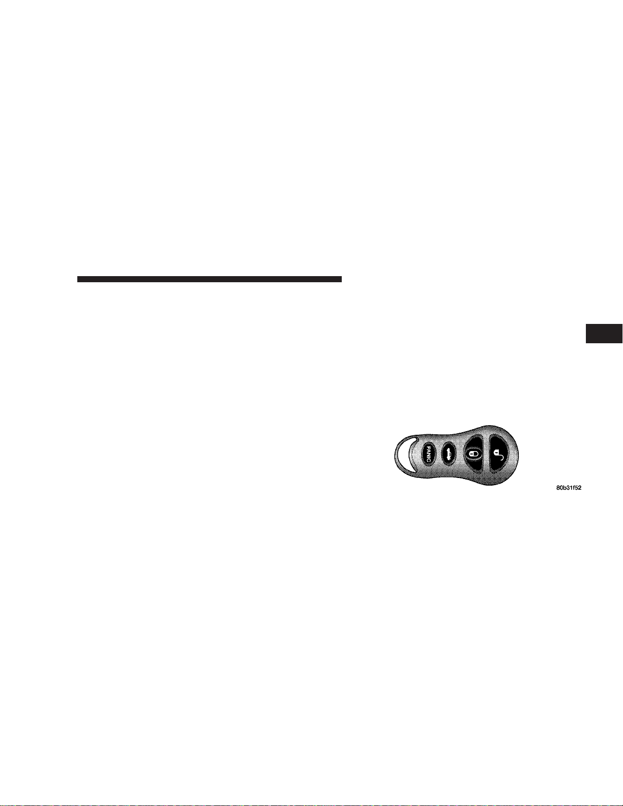
REMOTE KEYLESS ENTRY
This feature allows you to lock or unlock the doors from
distances up to 23 feet (7 meters) using a hand held
transmitter. You do not have to point the transmitter at
the vehicle to activate the system.
2
Page 16

16 THINGS TO KNOW BEFORE STARTING YOUR VEHICLE
To Unlock the Doors:
Press and release the UNLOCK button on the transmitter.
The front and rear park/turn signal lights will blink once
to indicate that only the driver’s door is unlocked. When
the unlock button is pressed twice, if pressed within 5
seconds, the front and rear park/turn signal lights will
blink twice to indicate that both doors are unlocked.
DOOR UNLOCKED in the odometer display will blink
continuously if one door is unlocked. DOOR UNLOCKED will remain steadily on in the odometer display
if both doors are unlocked. No message will be displayed
if both doors are locked.
NOTE: The system may be programmed to unlock both
doors upon the first press of the Unlock button. To toggle
between the first press unlock of the driver’s door to
unlock both doors, perform the following procedure:
1. Press and hold the Unlock button on the transmitter.
2. Continue to hold the Unlock button, wait at least 4 but
no longer than 10 seconds, then press the Lock button.
3. Release both buttons.
The park and tail lights will blink twice to acknowledge
the unlock signal.
NOTE: The Lamp Flash can be enabled or disabled by
performing the following procedure:
1. Press and hold the Lock button on the transmitter.
2. Continue to hold the Lock button, wait at least 4 but
no longer than 10 seconds, then press the Trunk button.
3. Release both buttons.
Page 17

THINGS TO KNOW BEFORE STARTING YOUR VEHICLE 17
To Lock the Doors:
NOTE: To enable/disable the Lamp Flash, see procedure described above.
Press and release the LOCK button on the transmitter.
The horn will chirp once and the park and tail lights will
blink to acknowledge that the door is locked and that the
alarm system is armed. The horn chirp can be disabled at
the dealership if so desired.
NOTE: The horn chirp feature can be enabled or disabled by performing the following procedure:
1. Press and hold the Lock button on the transmitter.
2. Continue to hold the Lock button, wait at least 4 but
no longer than 10 seconds, then press the Unlock button.
3. Release both buttons.
To Unlock the Trunk:
Press and hold the trunk button on the transmitter to
unlatch the trunk. The front and rear park/turn signal
lights will blink 3 times.
Panic Alarm
The panic alarm unlocks the driver’s door, turns on the
interior lights, flashes the park and fog lights and sounds
the horn for 3 minutes or until the alarm is turned off.
Panic mode does not work when the vehicle is driven.
To Use the Panic Alarm:
Press and hold the Panic button to activate the alarm.
Press and hold the Panic button or turn the key in the
ignition to the RUN position to deactivate the alarm. The
alarm will also shut itself off after 3 minutes.
2
Page 18

18 THINGS TO KNOW BEFORE STARTING YOUR VEHICLE
To Program Transmitters:
This feature allows you to program transmitters in case
one is lost or an extra transmitter(s) is desired. Up to 4
transmitters can be programmed to your vehicle. To
program another transmitter follow these steps:
1. Turn the ignition switch to the ON/RUN position and
set the parking brake.
2. Using a previously programmed transmitter, press the
UNLOCK button for 5 to 10 seconds. While the UNLOCK
button is being pressed (after 5 seconds), press the
PANIC button and release both buttons simultaneously.
You will hear a chime sound to signal you that programming on the transmitter(s) may occur.
3. You may program up to 4 transmitters for your vehicle
within a 30 second time limit. Press and release both
LOCK and UNLOCK buttons of a new transmitter at the
same time; then press and release any of the buttons
once, you will hear a chime when the transmitter has
been successfully programmed. A chime will sound
when the 30 seconds is over, or if you turn the ignition
switch OFF.
4. You must repeat step 3 for all new transmitters that
will be used with this vehicle (up to 4 total).
If you do not have a programmed transmitter, contact
your dealer for details.
General Information
This transmitter complies with FCC rules part 15. Operation is subject to the following conditions:
1. This device may not cause harmful interference.
2. This device must accept any interference that may be
received, including interference that may cause undesired operation.
Page 19
THINGS TO KNOW BEFORE STARTING YOUR VEHICLE 19
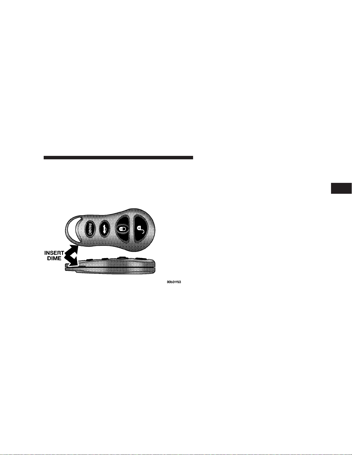
Transmitter Battery Service
The replacement battery number is 2016. This is a generic
battery, readily available at local retail stores.
1. Pry the transmitter halves apart with a coin or similar
object.
2. Remove and replace the batteries.
3. Reassemble the transmitter case and test operation.
NOTE: If the transmitter is operated more than 255
times out of range of the vehicle (23 feet or 7 meters) or
when the vehicle battery is dead, it may become “out of
synch”. The result is that the transmitter will not function.
To correct this condition, remove the key from the
ignition and close the hood and all doors. Press both
buttons on the transmitter for about 10 seconds. The horn
will chirp once to acknowledge the signal. Normal transmitter operation should resume.
VEHICLE THEFT ALARM
The system monitors the doors, trunk, hood, and ignition
for unauthorized operation.
Once the system has been armed, opening any door,
trunk (with the ignition key), hood or turning the ignition
key to any position will trigger an alarm.
2
Page 20

20 THINGS TO KNOW BEFORE STARTING YOUR VEHICLE
If something triggers the alarm, the system will signal for
about 18 minutes. For the first 3 minutes the horn will
sound and the park, tail and fog lights will flash. If the
condition which triggered the alarm is still present, the
park, tail and fog lights will continue to flash for 15
minutes, unless the trigger condition is cleared sooner.
NOTE: The engine will not start until the system is
disarmed.
To Arm the Vehicle Theft Alarm System
There are two methods to arm the Vehicle Theft Alarm
system:
1. Press the Lock button on the Remote Keyless Entry.
The optical and audible horn chirp will sound if it is
enabled. (See Remote Keyless Entry section of this
manual)
2. Remove the keys from the ignition and, with the door
open, press the Lock button on the door trim panel and
close the door.
3. After the last door is closed, the security light will
flash for 15 seconds. If there is a fault in the system or if
the hood or trunk is not closed, the Vehicle Theft Alarm
lamp will remain ON steady for 15 seconds until the
system is armed. (See the dealer if the system is faulted)
The arming sequence will cancel if the door is opened or
the ignition is turned on. Opening the hood or trunk will
not cancel the arming process.
Page 21
THINGS TO KNOW BEFORE STARTING YOUR VEHICLE 21
CAUTION!
4. The Security light will periodically flash, once every 6
seconds, to show that the system is still armed.
If the Security lamp flashes twice every 6 seconds,
then the vehicle was tampered with!
Entering the Trunk with the System Armed
To enter the trunk with the system armed, the Remote
Keyless Entry Trunk button must be pressed. This will
pop the trunk open and allow access without alarming or
disarming the Vehicle Theft Alarm System.
NOTE: If the key is used and the system is armed, then
the Vehicle Theft Alarm System will start alarming.
2
Page 22
22 THINGS TO KNOW BEFORE STARTING YOUR VEHICLE
Security System Disarm
There are two ways to disarm the system:
1. Driver door key cylinder: Insert the key in the cylinder
located under the driver’s door mirror. This will disarm
the Vehicle Theft Alarm System and open the driver’s
door.
2. Or, press the UNLOCK button on the Remote Keyless
Entry transmitter. The front and rear park and turn signal
lights will flash to acknowledge the signal. (See the
Remote Keyless Entry Section of this manual for operation)
NOTE: The vehicle will not start unless the Vehicle
Theft Alarm System is disarmed by either of the two
methods above. Inserting the key in the ignition WILL
NOT disarm the system (it will start the alarming process!)
Page 23

THINGS TO KNOW BEFORE STARTING YOUR VEHICLE 23
Tamper Alert
If the horn sounds 3 times when you unlock the vehicle
using the Remote Keyless Entry transmitter or key, the
alarm has been activated. Check the vehicle for tampering.
NOTE: If the Security lamp flashes twice every 6
seconds, then the vehicle was tampered with.
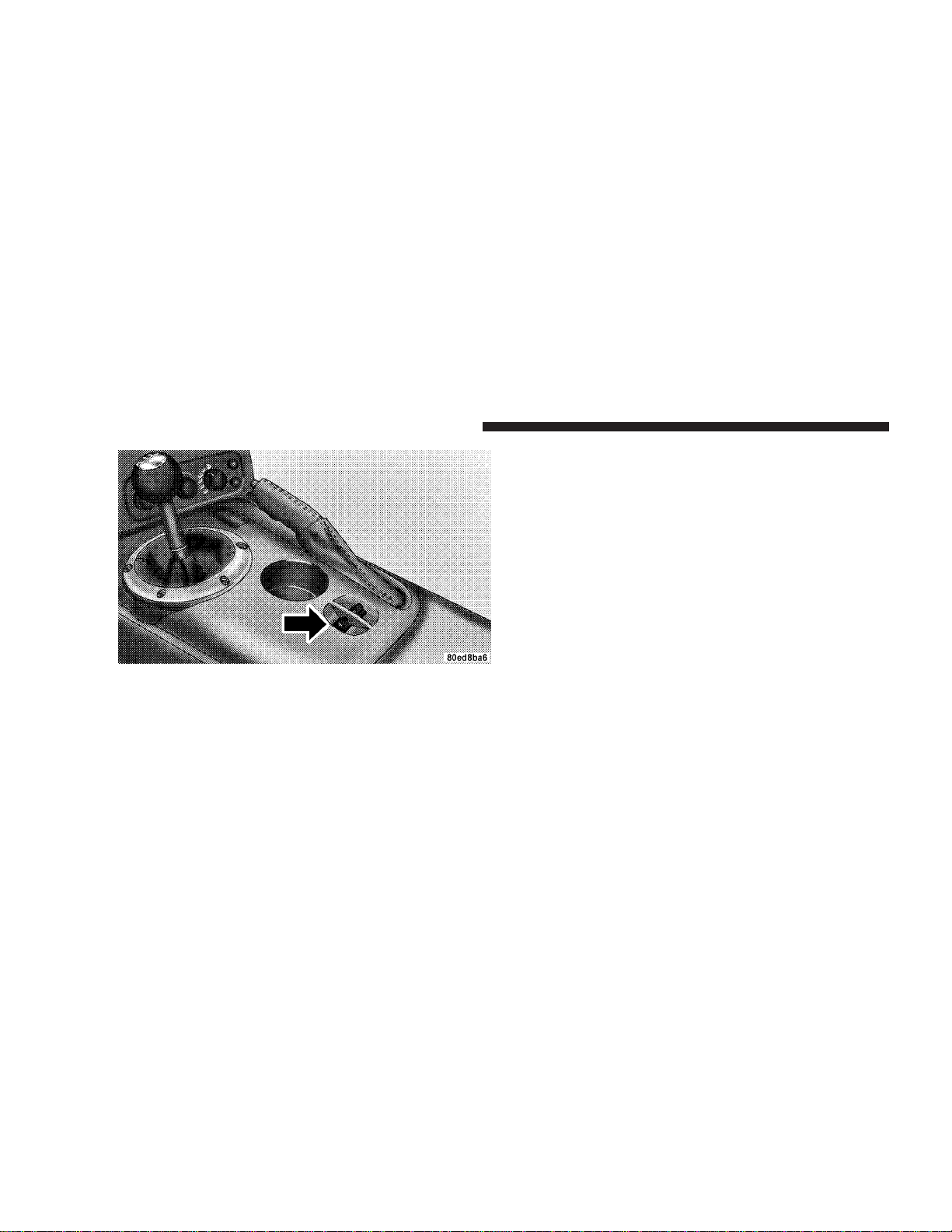
WINDOWS
Power Windows
The power window switches are located between the
driver and passenger seats on the center tunnel bezel, just
to the left of the parking brake. The switch on the left side
controls the driver’s window and the switch on the right
controls the passenger’s window. The power window
switches are active when the ignition is in RUN or
ACCESSORY.
The power window switch also works during accessory
delay. This delay feature will allow the windows to be
functional up to 2 minutes after the vehicle has been
turned off. This feature can be disabled at the dealership
if desired.
NOTE: Windows cannot be driven up during accessory
delay with a door open.
NOTE: If the windows are completely closed, each
respective window will drop slightly when either door is
opened. The windows return to their full up position
when the door is again closed. This is necessary to clear
the seal when either door is opened.
2
Page 24
24 THINGS TO KNOW BEFORE STARTING YOUR VEHICLE
Auto Down Feature
Both windows have an auto down feature. Press the
window switch to the second detent, release, and the
window will go down automatically. Press the switch a
second time in either direction to stop the window.
To open the window to a desired positon, press and hold
the window switch in the first detent until the window
has reached the desired position and then release it when
you want the window to stop.
Power Accessory Delay Feature
The Power Accessory Delay feature provides the customer with the ability to operate the power windows,
and the radio for 2 minutes after the ignition switch is
turned off. If the key is removed from the ignition and the
driver door is opened prior to the completion of the
2–minute timer, the feature is immediately cancelled. The
Power Accessory Delay feature is initially enabled, but
may be enabled or disabled at the dealership.
NOTE: The Window Up switch will not function with
the door open and while the system is in the Power
Accessory Delay mode. If the window is in the process of
going up, opening the door will stop the window movement immediately.
Page 25
THINGS TO KNOW BEFORE STARTING YOUR VEHICLE 25
Wind Buffeting
Wind buffeting can be described as the perception of
pressure on the ears or a helicopter-type sound in the
ears. Your vehicle may exhibit wind buffeting with the
windows down, or the top down. This is a normal
occurrence and can be minimized.
TRUNK SAFETY WARNING
WARNING!
Do not allow children to have access to the trunk,
either by climbing into the trunk from outside, or
through the inside of the vehicle. Always close the
trunk lid when your vehicle is unattended. Once in
the trunk, young children may not be able to escape.
If trapped in the trunk, children can die from suffocation or heat stroke.
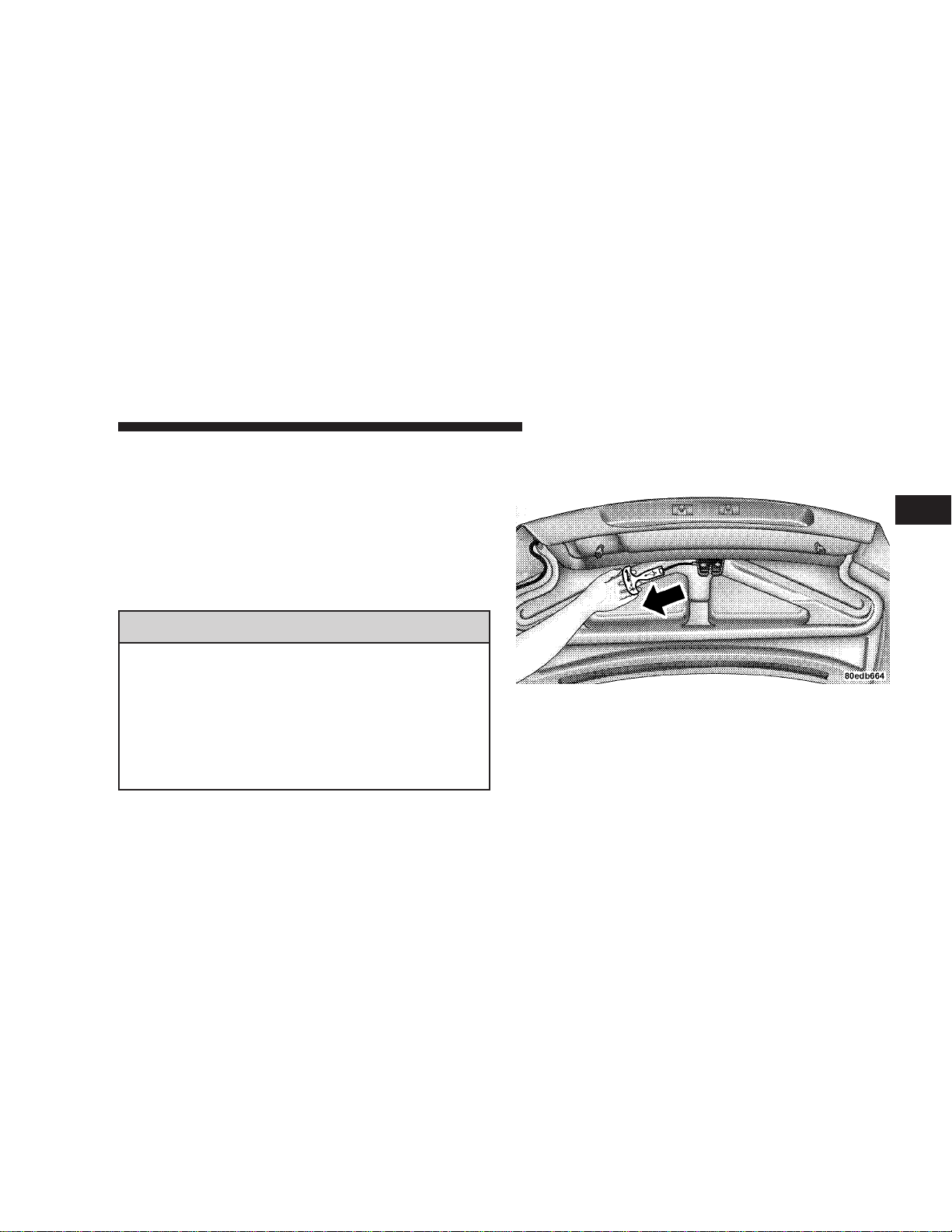
Trunk Internal Emergency Release
2
NOTE: As a security measure, a Trunk Internal Emergency Release lever is built into the trunk latching
mechanism. In the event of an individual being locked
inside the trunk, the trunk can simply be opened by
Page 26

26 THINGS TO KNOW BEFORE STARTING YOUR VEHICLE
pulling on the lever attached to the trunk latching
mechanism, which is coated so that it glows in a darkened trunk.
OCCUPANT RESTRAINTS
One of the most important safety features in your Viper
is the restraint system. This system consists of the driver’s and passenger’s seat belts, airbags for the driver and
passenger, and a passenger airbag on/off switch located
in the center console compartment for deactivating the
passenger airbag system.
Please pay close attention to the information in this
section. It tells you how to use your restraint system
properly to keep you and your passenger as safe as
possible. Whichever system you have, all of the warnings
in this section apply.
WARNING!
In a collision, you and your passenger can suffer
much greater injuries if you are not properly buckled up. You can strike parts of the inside of your
vehicle or your passenger, or you can be thrown out
of the vehicle. Always be sure you and your passenger are buckled up properly.
Buckle up even though you are an excellent driver. Even
on short trips. Someone on the road may be a poor driver
and cause a collision that includes you. And this can
happen far away from home or on your street.
Research has shown that seat belts save lives. They also
can reduce the seriousness of injuries in a collision. Some
of the worst injuries happen when people are thrown
from the vehicle. Seat belts provide protection against
Page 27
THINGS TO KNOW BEFORE STARTING YOUR VEHICLE 27
that, and they reduce the risk of injury caused by striking
the inside of the vehicle. Everyone in a motor vehicle
needs to be buckled up all the time.
Lap/Shoulder Belts
Each seat belt is a combined lap/shoulder belt system.
The belt webbing retractor will lock only during very
sudden stops or impacts. This feature allows the shoulder
part of the belt to move freely with you under normal
conditions. But, in a collision, the belt will lock and
reduce the risk of your striking the inside of the vehicle or
being thrown out.
WARNING!
Wearing a seat belt incorrectly is dangerous. Seat
belts are designed to go around the large bones of
your body. These are the strongest parts of your body
and can take the forces of a collision the best.
Wearing your belt in the wrong place could make
your injuries in a collision much worse. You might
suffer internal injuries, or you could even slide out
of part of the belt. Follow these instructions to wear
your seat belt safely and to keep your passengers
safe, too.
2
Page 28
28 THINGS TO KNOW BEFORE STARTING YOUR VEHICLE
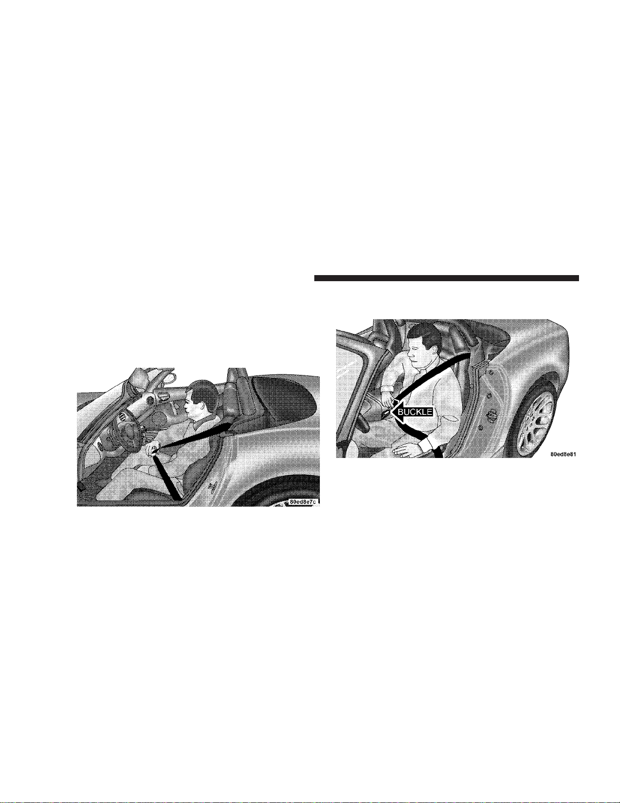
Lap/Shoulder Belt Operating Instructions
1. Enter the vehicle and close the door. Sit back and
adjust the seat.
2. The seat belt latch plate is located at the side of your
seat back. Grasp the latch plate and pull out the belt.
3. Slide the latch plate up the webbing as far as necessary
to make the belt go around your lap.
4. When the belt is long enough to fit, insert the latch
plate into the buckle until you hear a “click.”
Page 29
WARNING!
A belt that is too loose will not protect you as well. In
a sudden stop you could move too far forward,
increasing the possibility of injury. Wear your seat
belt snugly.
A belt that is worn under your arm is very dangerous. Your body could fall into the inside surfaces of
the vehicle in a collision, increasing head and neck
injury. And a belt worn under the arm can cause
internal injuries. Ribs aren’t as strong as shoulder
bones. Wear the belt over your shoulder so that your
strongest bones will take the force in a collision.
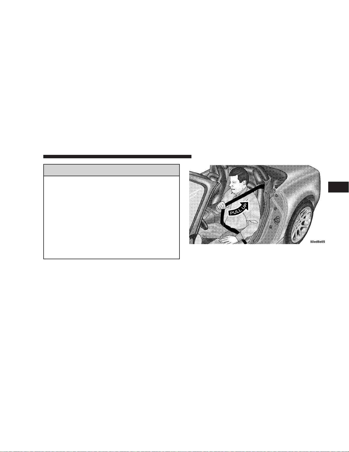
5. Position the lap belt across your thighs, below your
abdomen. To remove slack in the lap belt portion, pull up
a little on the shoulder belt, as shown.
THINGS TO KNOW BEFORE STARTING YOUR VEHICLE 29
2
6. To loosen the lap belt if it is too tight, tilt the latch plate
and pull on the lap belt. A snug belt reduces the risk of
sliding under the belt in a collision.
Page 30

30 THINGS TO KNOW BEFORE STARTING YOUR VEHICLE
WARNING!
A lap belt worn too high can increase the risk of
internal injury in a collision. The belt forces won’t
be at the strong hip and pelvic bones, but across your
abdomen. Always wear the lap belt as low as possible and keep it snug.
7. Position the shoulder belt on your chest so that it is
comfortable and not resting on your neck. The retractor
will withdraw any slack in the belt.
WARNING!
A twisted belt can’t do its job as well. In a collision
it could even cut into you. Be sure the belt is straight.
If you can’t straighten a belt in your vehicle, take it
to your dealer and have it fixed.
8. To release the belt, push the red button marked PRESS
on the buckle. The belt will automatically retract to its
stowed position. If necessary, slide the latch plate down
the webbing to allow it to retract fully.
Enhanced Driver Seat Belt Reminder System
(BeltAlert™)
If the driver’s seat belt has not been buckled within 60
seconds of starting the vehicle and if the vehicle speed is
greater than 5 mph (8 km/h), the Enhanced Warning
System (BeltAlert™) will alert the driver to buckle their
seat belt. The driver should also instruct all other occupants to buckle their seat belts. Once the warning is
triggered, the Enhanced Warning System (BeltAlert™)
will continue to chime and flash the Seat Belt Warning
Light for 96 seconds or until the driver’s seat belt is
buckled. The Enhanced Warning System (BeltAlert™)
will be reactivated if the driver’s seat belt is unbuckled
for more than 10 seconds and the vehicle speed is greater
than 5 mph (8 km/h).
Page 31

THINGS TO KNOW BEFORE STARTING YOUR VEHICLE 31
The Enhanced Warning System (BeltAlert™) can be enabled or disabled by your authorized dealer or by
following these steps:
NOTE: The following steps must occur within the first
60 seconds of the ignition switch being turned to the ON
or START position. DaimlerChrysler does not recommend deactivating the Enhanced Warning System
(BeltAlert).
1. Turn the ignition switch to the OFF position and
buckle the driver’s seat belt.
2. Start the engine and wait for the Seat Belt Warning
Light to turn off.
3. Within 60 seconds of starting the vehicle, unbuckle
and then re-buckle the driver’s seat belt at least three
times within 10 seconds, ending with the seat belt
buckled.
4. Turn off the engine. A single chime will sound to
signify that you have successfully completed the programming.
The Enhanced Warning System (BeltAlert™) can be reactivated by repeating this procedure.
NOTE: Although the Enhanced Warning System (BeltAlert™) has been deactivated, the Seat Belt Warning Light
will continue to illuminate while the driver’s seat belt
remains unbuckled.
Six Point Belt System - If equipped
This six point belt system meets SCCA standards and
should be only used when engaged in related performance driving events. The standard lap/shoulder belt
should be used whenever the vehicle is operated on the
street.
2
Page 32

32 THINGS TO KNOW BEFORE STARTING YOUR VEHICLE
Six Point Belt Operating Instructions
With the anti-submarining belt placed on the seat pointing up, buckle the left and right lap belts and strap both
legs. Buckle the left and right shoulder belts. Adjust the
belts by pulling on the web ends and/or re-positioning
the web clips and straps as required. Release the belts by
turning the belt latch mechanism1⁄4turn in either the
clockwise or counter-clockwise direction.
NOTE: The anti-submarining belt and the shoulder belt
are attached to eye bolts at designated locations and
should be removed from the vehicle when not in use. The
lap belts and straps can be stored behind or to the sides
of the seat after removal.
Seat Belts and Pregnant Women
We recommend that pregnant women use the seat belts
throughout their pregnancy. Keeping the mother safe is
the best way to keep the baby safe.
Pregnant women should wear the lap part of the belt
across the thighs and as snug across the hips as possible.
Keep the belt low so that it does not come across the
abdomen. That way the strong bones of the hips will take
the force if there is a collision.
Seat Belt Extender
If a seat belt is too short, even when fully extended, your
dealer can provide you with a seat belt extender. This
extender should be used only if the existing belt is not
long enough.
Page 33

THINGS TO KNOW BEFORE STARTING YOUR VEHICLE 33
WARNING!
A frayed or torn belt could rip apart in a collision
and leave you with no protection. Inspect the belt
system periodically, checking for cuts, frays, or loose
parts. Damaged parts must be replaced immediately.
Do not disassemble or modify the system. Seat belt
assemblies must be replaced after an accident if they
have been damaged (bent retractor, torn webbing,
etc.)
Child Restraint
Everyone in your vehicle needs to be buckled up all the
time, babies and children, too.
WARNING!
In a collision, an unrestrained child, even a tiny
baby, can become a missile inside the vehicle. The
force required to hold even an infant on your lap
could become so great that you could not hold the
child, no matter how strong you are. The child and
others could be badly injured. Any child riding in
your vehicle should be in a proper restraint for the
child’s size.
All states and Canadian provinces require small
children to ride in proper restraint systems. This is
the law, and you can be prosecuted for ignoring it.
Infants and Small Children
There are two different sizes and types of restraints for
children from newborn size to the bigger child almost
large enough for an adult seat belt. Always check the
2
Page 34

34 THINGS TO KNOW BEFORE STARTING YOUR VEHICLE
child seat owner’s manual to ensure you have the right
seat for your child. Use the restraint system that is correct
for your child.
Two different child restraint systems are generally available:
•
The infant carrier for babies weighing up to approximately 20 lbs. (9 kg).
•
The child seat for small children over 20 lbs. (9kg).
WARNING!
A rearward facing infant restraint must not be used
in your Viper unless the passenger airbag has been
shut off. A rearward facing infant restraint may be
struck by a deploying passenger airbag which may
cause severe or fatal injury to the infant.
In addition, some manufacturers make systems that can
be first used as an infant carrier, then converted to a child
seat as the child grows.
Here are some tips on getting the most out of your child
restraint.
Before buying any restraint system, make sure that it has
a label certifying that it meets Motor Vehicle Safety
Standard 213. The manufacturer also recommends that
before you buy a child restraint, you try it in the seat
where you will use it.
The restraint must be appropriate for your child’s weight
and height. Check the label on the restraint for this too.
Carefully follow the instructions that came with the
restraint. If you install the restraint improperly, it may not
work when you need it.
Page 35

THINGS TO KNOW BEFORE STARTING YOUR VEHICLE 35
WARNING!
Improper installation can lead to failure of a child
restraint. It could come loose in a collision. The child
could be badly injured or killed. Follow the manufacturer’s directions exactly when installing a child
restraint.
•
Child restraints are secured in the passenger seat by
the lap part of the lap/shoulder belt.
Buckle the child into the seat exactly as the child seat
manufacturer’s directions tell you. The cinching latch
plate on the lap/shoulder belt will keep the belt tight.
When your infant carrier or child seat is not in use, secure
it with the seat belt or remove it from the vehicle. Don’t
leave it loose in the vehicle. In a sudden stop or collision,
it could strike occupants and injure them.
LATCH — Lower Anchors and Tether for CHildren
2
Your vehicle’s passenger seat is equipped with the child
restraint anchorage system called LATCH, which stands
for Lower Anchors and Tether for Children. The LATCH
system provides for the installation of the child restraint
without using the vehicle seat belt. The passenger seat
has an exclusive lower anchorage.
Page 36

36 THINGS TO KNOW BEFORE STARTING YOUR VEHICLE
These are round bars, located at the lower area of the seat
back, one on each side of the passenger seat. You will
easily feel them if you run your finger along the intersection of the surface. Install your child seat as per child
seat manufacturer recommendations.
NOTE: If your child restraint seat is not LATCH compatible, install the restraint using the vehicle seat belts.
Child Restraint Tether Anchor
Child restraints having tether straps and hooks for connection to tether anchors have been available for some
time. In fact, many child restraint manufacturers will
provide add-on tether strap kits for some of their older
products. There is a tether strap anchor located in the
child tether access cover behind the passenger seat.
Remove the child tether access cover by prying either
side with a screwdriver or similar tool, as shown in
illustration which follows. While the child tether is in
use, keep the access cover in a safe place so that it can be
replaced after use of the child tether.
To attach the tether strap to the anchor, move the
seatback fully forward. Pass the child restraint tether
hook through either opening in the seatback under the
head restraint. Attach the tether hook to the anchor loop,
Page 37

THINGS TO KNOW BEFORE STARTING YOUR VEHICLE 37
recline the seatback full rearward and move the seat to its
most rearward position. Install the child restraint according to the manufacturer’s directions. Return the seatback
to an upright position. Remove slack from the tether
strap according to the child restraint manufacturer’s
directions.
WARNING!
An incorrectly anchored tether strap could lead to
increased head motion and possible injury to the
child. Use only the anchor position directly behind
the child seat to secure a child restraint top tether
strap.
Children Too Large For Child Seats
Children who are too large for child seats and who can sit
upright by themselves should use the lap/shoulder belt
for best protection.
•
Make sure that the child is seated upright in the seat.
•
The lap belt should be low on the hips and as snug as
possible.
•
Check belt fit periodically. A child’s squirming or
slouching can move the belt out of position.
2
Page 38

38 THINGS TO KNOW BEFORE STARTING YOUR VEHICLE
•
If the shoulder belt contacts the face or neck, move the
child closer to the side of the vehicle.
Booster seats that may help overcome this problem are
also available for use with lap/shoulder belts. Before
buying a booster seat, make sure that it has a label
certifying that it meets applicable Motor Vehicle Safety
Standards. Make sure that it is satisfactory for use in this
vehicle.
Supplemental Restraint System (SRS) - Airbag
This vehicle has airbags for the driver and passenger as a
supplement to the seat belt restraint systems. The driver’s
airbag is mounted in the steering wheel. The passenger
side airbag is mounted in the instrument panel, under a
cover marked SRS/AIRBAG. These airbags inflate in
higher speed impacts. They work with the instrument
panel knee bolsters and the seat belts to provide improved protection for the driver and right front passenger.
WARNING!
•
Relying on the airbags alone could lead to more
severe injuries in a collision. The airbags work
with your seat belt to restrain you properly. In
some collisions the airbags won’t deploy at all.
Wear your seat belts even though you have airbags.
•
Being too close to the steering wheel or instrument panel during airbag deployment could cause
serious injury. Airbags need room to inflate. Sit
back, comfortably extending your arms to reach
the steering wheel or instrument panel.
The seat belts are designed to protect you in many types
of collisions. The airbags deploy only in frontal collisions
and will not deploy in collisions at slow speed. But even
Page 39

THINGS TO KNOW BEFORE STARTING YOUR VEHICLE 39
in collisions where the airbags deploy, you need the seat
belts to keep you in the right position for the airbags to
protect you properly.
Here are four simple steps you can take to minimize the
risk of harm from a deploying airbag.
1. Infants in rear facing child safety seats designed for
children up to one year or approximately 20 pounds (9
kg) should never ride in the front seat of a vehicle with
a passenger side airbag unless the airbag is shut OFF.
See “Passenger Side Airbag On/Off Switch.” An airbag
deployment can cause severe injury or death to infants in
this position.
Children that are not big enough to properly wear the
vehicle seat belt (see section on “Child Restraint”) should
be secured in child safety seats or booster seats.
Older children who do not use child safety seats or
booster seats should ride properly buckled.
Never allow children to place the shoulder belt behind
them or under the arm.
Infants up to 1 year or approximately 20 pounds (9 kg)
should never ride in the vehicle, because the rear facing
child seat places them too close to the passenger air bag
in the event of a crash.
Children from 1 to 12 years old: Move the passenger seat
as far back as possible. Children from 20 to 60 pounds (9
kg to 27 kg) should be secured in the appropriate child
safety seat or booster seat. If too large for a booster seat,
the child should wear the lap/shoulder belt properly.
Children should never be allowed to lean forward toward the instrument panel as a passenger air bag deployment could cause severe injury or death to a child in this
position.
You should read the instructions provided with your
child restraint to make sure that you are using it properly.
2
Page 40

40 THINGS TO KNOW BEFORE STARTING YOUR VEHICLE
2. All occupants should wear their lap and shoulder
belts properly.
3. The driver and passenger seats should be moved
back as far as practical to allow the airbags room to
inflate. Additionally, the pedals are power adjustable,
so the driver seat can be moved back and the pedals
moved closer as needed so the driver can be as far from
the airbag as possible. (See section on Power Adjustable Pedals for operation.)
4. You should read the instructions provided with your
child safety or booster seat to make sure that you are
using it properly.
The airbag system consists of the following:
•
Airbag control module and internal crash sensor
•
AIRBAG Readiness Light
•
Driver and Passenger Airbag/inflator Units
•
Passenger Side Airbag On/Off Switch
•
Passenger Airbag Off Indicator Light
•
Unique Steering Wheel and Column
•
Unique Instrument Panel
•
Interconnecting Wiring
•
Knee Impact Bolster
How The Airbag System Works
A crash sensor in the occupant compartment deter-
•
mines if a frontal impact is severe enough to require
the airbag. The sensor will not detect side, roll over, or
rear impacts. The crash sensor is connected to the
diagnostic unit and to the airbag/inflator unit.
•
The Diagnostic Unit monitors the readiness of the
electronic parts of the system whenever the ignition
switch is in the START or RUN position. These include
Page 41

THINGS TO KNOW BEFORE STARTING YOUR VEHICLE 41
all of the items listed above except the knee bolster, the
instrument panel, and the steering wheel and column.
The Diagnostic Unit also turns on the AIRBAG light in
the instrument panel for 6 to 8 seconds when the
ignition is first turned on, then turns the light off. If it
detects a malfunction in any part of the system, it turns
on the light either momentarily or continuously.
•
The Airbag/Inflator Units are in the center of the
steering wheel and in the instrument panel. The words
SRS/AIRBAG are embossed on the airbag covers.
WARNING!
Ignoring the AIRBAG light inyour instrument panel
could mean you won’t have the airbags to protect
you in a collision. If the light does not come on, stays
on after you start the vehicle, or if it comes on as you
drive, have the airbag system checked right away.
WARNING!
Do not put anything on or around the airbag covers
or attempt to manually open them. You may damage
the airbags and you could be injured because the
airbags are not there to protect you. These protective
covers for the airbag cushions are designed to open
only when the airbags are inflating.
•
When the crash sensors detect an impact requiring the
airbags, they signal the inflator units. A large quantity
of non toxic nitrogen gas is generated to inflate the
airbags. The airbag covers separate and fold out of the
way as the airbags inflate to their full size. The airbags
fully inflate in about 50 milliseconds. This is only
about half of the time it takes you to blink your eyes.
The airbags then quickly deflate while helping to
restrain the driver and right front passenger. The
airbag gas is vented through the airbag material
2
Page 42

42 THINGS TO KNOW BEFORE STARTING YOUR VEHICLE
towards the instrument panel. In this way the airbags
do not interfere with your control of the vehicle.
•
The Knee Impact Bolsters help protect the knees and
position you for the best interaction with the airbags.
If A Deployment Occurs
The airbag system is designed to deploy when the impact
sensors detect a moderate to severe frontal collision, to
help restrain the driver and right front passenger, and
then to immediately deflate.
NOTE: A frontal collision that is not severe enough to
need airbag protection will not activate the system. This
does not mean something is wrong with the airbag
system.
If you do have a collision which deploys the airbags, any
or all of the following may occur:
•
The nylon airbag material may sometimes cause abrasions and/or skin reddening to the driver and right
front passenger as the airbags deploy and unfold. The
abrasions are similar to friction rope burns or those
you might get sliding along a carpet or gymnasium
floor. They are not caused by contact with chemicals.
They are not permanent and normally heal quickly.
However, if you haven’t healed significantly within a
few days, or if you have any blistering, see your doctor
immediately.
•
As the airbags deflate you may see some smoke-like
particles. The particles are a normal by-product of the
process that generates the non toxic nitrogen gas used
for airbag inflation. These airborne particles may irritate the skin, eyes, nose, or throat. If you have skin or
eye irritation, rinse the area with cool water. For nose
or throat irritation, move to fresh air. If the irritation
continues, see your doctor. If these particles settle on
your clothing, follow the garment manufacturer’s instructions for cleaning.
Page 43

THINGS TO KNOW BEFORE STARTING YOUR VEHICLE 43
•
Your vehicle may be safely driveable after the airbags
deploy. If so, you can tuck the deployed airbags inside
the opening in the steering wheel hub and instrument
panel trim covers to make driving somewhat easier.
WARNING!
Deployed airbags can’t protect you in another collision. Have the airbags replaced by an authorized
dealer as soon as possible.
Passenger Side AirBag On/Off Switch
The passenger airbag is to be turned off only if the
passenger:
•
is an infant (less than 1 year old) who must ride in the
front seat because thereis no rear seat, because the rear
seat is too small for a rear-facing infant restraint or
because the infant has a medical condition which
makes it necessary for the driver to be able to see the
infant,
•
is a child, age 1 to 12 who must ride in the front seat
because there is no rear seat, because there is no rear
seat position available, or because the child has a
medical condition which makes it necessary for the
driver to be able to see the child,
•
has a medical condition which makes passenger airbag
inflation (deployment) a greater risk for the passenger
than the risk of hitting the dashboard (instrument
panel) or windshield in a crash.
If the airbag is turned off when there is any other
occupant at that position, the supplemental restraint
provided by the airbag will not be available.
2
Page 44

44 THINGS TO KNOW BEFORE STARTING YOUR VEHICLE
To turn OFF the passenger side airbag, use the on/off
switch located in the center console.
NOTE: When the passenger airbag is turned off the
airbag off light will illuminate
To Shut Off the Passenger Airbag:
•
Place only the tip of the ignition key in the on/off
switch, turn the key clockwise, and remove the key
from the switch. This will shut off the passenger side
airbag. The PASS AIRBAG OFF light on the instrument
panel will illuminate when the ignition switch is
turned to the ON position.
Page 45

THINGS TO KNOW BEFORE STARTING YOUR VEHICLE 45
To Turn On The Passenger Airbag:
•
Place the ignition key in the on/off switch, turn the
key counterclockwise, and remove the key from the
switch. This will turn on the passenger side airbag.
The light on the instrument panel will be off when the
ignition switch is turned to the ON position.
WARNING!
The airbag may malfunction and serious injury
could result if key is left in the airbag shut off
switch. Always remove the key.
Maintaining Your Airbag System
WARNING!
•
Modifications to any part of the airbag system
could cause it to fail when you need it. You could
be injured because the airbag is not there to
protect you. Do not modify the components or
wiring, including adding any kind of badges or
stickers to the airbag covers. Do not modify the
front bumper or vehicle body structure.
•
You need proper knee impact protection in a
collision. Do not mount or locate any aftermarket
equipment on or behind the knee impact bolsters.
•
You can be injured if you are too close to either
airbag cover when the airbags inflate. It is dangerous to try to repair any part of the airbag
system yourself. Don’t try to repair the airbag
system. Be sure to tell anyone who works on your
vehicle that it has airbags.
2
Page 46

46 THINGS TO KNOW BEFORE STARTING YOUR VEHICLE
You will want to have the airbags ready for your protection in a collision. While the airbag Supplemental Restraint System (SRS) is designed to be maintenance free,
if any of the following occurs, have an authorized dealer
service the system immediately.
•
The AIRBAG light does not come on or flickers during
the 6 to 8 seconds when the ignition switch is first
turned on.
•
The light remains on or flickers after the 6 to 8 second
interval.
•
The light flickers or comes on and remains on while
driving.
Transporting Pets
Deploying airbags could harm your pet. An unrestrained
pet will be thrown about and possibly injured, or injure a
passenger during panic braking or in a collision.
Pets should be restrained in pet harnesses or pet carriers
that are secured by seat belts.
ENGINE BREAK-IN RECOMMENDATIONS
The engine in your new Viper does not require a long
break-in period. Following these few simple guidelines is
all that is necessary for a good break-in:
For the first 500 miles (800 km):
•
Keep your vehicle speed below the legal, posted speed
limit and your engine speed below 4,000 rpm.
•
Avoid driving at a constant speed, either fast or slow,
for long periods of time.
•
Do not make any full throttle starts and avoid full
throttle acceleration.
•
Use the proper gear for your speed range.
Page 47

•
Wait until the engine has reached normal operating
temperature before driving at the recommended maximum break-in speed.
•
Avoid excessive idling.
•
Check the engine oil level at every fuel fill.
NOTE: A new engine will consume some oil during the
first few thousand miles of operation. This should be
considered as a normal part of the break-in and not
interpreted as a sign of difficulty.
THINGS TO KNOW BEFORE STARTING YOUR VEHICLE 47
SAFETY TIPS
Exhaust Gas
WARNING!
Exhaust gases can injure or kill. They contain carbon
monoxide (CO) which is colorless and odorless.
Breathing it can make you unconscious and can
eventually poison you. To avoid breathing (CO)
follow the safety tips below.
•
Do not run the engine in a closed garage or in confined
areas any longer than needed to move your vehicle in
or out of the area.
•
If it is necessary to sit in a parked vehicle with the
engine running, adjust your heating or cooling controls to force outside air into the vehicle. Set the blower
at high speed.
2
Page 48

48 THINGS TO KNOW BEFORE STARTING YOUR VEHICLE
Safety Checks You Should Make Inside the
Vehicle
Seat Belts
Inspect the belt system periodically, checking for cuts,
•
frays and loose parts. Damaged parts must be replaced
immediately. Do not disassemble or modify the system.
•
Seat belt assemblies must be replaced after an accident
if they have been damaged (bent retractor, torn webbing, etc.). If there is any question regarding belt or
retractor condition, replace the belt.
Defrosters
Check operation by selecting the defrost mode and place
the blower control on high speed. You should be able to
feel the air directed against the windshield.
Safety Checks You Should Make Outside the
Vehicle
Tires
Examine tires for excessive tread wear or uneven wear
patterns. Check for stones, nails, glass, or other objects
lodged in the tread. Inspect for tread cuts or side wall
cracks. Check wheel nuts for tightness and tires for
proper pressure.
Lights
Have someone observe the operation of exterior lights
while you work the controls. Check turn signal and high
beam indicator lights on the instrument panel.
Fluid Leaks
Check area under vehicle after overnight parking for fuel,
water, oil, or other fluid leaks. Also, if gasoline fumes are
present, the cause should be corrected immediately.
Page 49

UNDERSTANDING THE FEATURES OF YOUR VEHICLE
CONTENTS
m Convertible Top Operation .................51
▫ Manual Front Seat Adjustments ............57
3
▫ To Raise The Top ......................51
▫ To Lower The Top ......................53
m Console Features ........................54
m Mirrors ...............................55
▫ Inside Day/Night Mirror .................55
▫ Electric Remote Control Mirrors ............55
▫ Mirror Adjustment .....................56
m Seats .................................57
▫ Reclining Seat .........................57
m To Open And Close The Hood ..............58
m Lights ................................60
▫ Courtesy/Reading Lights .................60
▫ Interior Lights ........................61
▫ Multi-Function Control Lever ..............61
▫ Headlights, Parking Lights, Instrument Panel
Lights, And Front Fog Lights ..............62
Page 50

50 UNDERSTANDING THE FEATURES OF YOUR VEHICLE
▫ Daytime Running Lights .................63
▫ Lights-On Reminder ....................63
▫ Headlight Time Delay ...................63
▫ Battery Saver Feature — Exterior Lights ......63
▫ Fog Lights ...........................64
▫ Turn Signals ..........................64
▫ Highbeam/Lowbeam Select Switch ..........65
▫ Passing Light .........................65
m Tilt Steering Column .....................65
m Adjustable Pedals .......................66
▫ Adjustable Left Foot Rest .................67
m Windshield Wipers And Washers .............68
▫ Windshield Washers ....................69
▫ Mist Function .........................69
▫ Intermittent Wiper System ................69
Page 51

CONVERTIBLE TOP OPERATION
To Raise the Top:
1. To raise the convertible top, first ensure that the door
windows are lowered at least an inch.
2. Then open the trunk.
3. Release the lever located behind the driver’s seat and
nestled in the folded convertible top (as pictured). To aid
in disengaging the latch, press down on the convertible
top while pressing on the latch lever.
UNDERSTANDING THE FEATURES OF YOUR VEHICLE 51
3
Page 52

52 UNDERSTANDING THE FEATURES OF YOUR VEHICLE
4. Manually raise the top until it meets the windshield
header (as pictured).
5. Close the trunk.
6. While sitting inside the vehicle, hold onto the handles
and pull the top towards the windshield header. Push the
latch handle forward and engage the latch hook to the
windshield receiver rod.
Page 53

UNDERSTANDING THE FEATURES OF YOUR VEHICLE 53
7. Ensure the outboard locating pins are in their respective receiving holes in the windshield header. Push the
latch handle forward all the way to close the latch.
NOTE: Until the convertible top system has had adequate time to break in, it may take greater effort to
engage the latch hook and close the latch. Several weeks
of normal convertible top usage will reduce these efforts.
To Lower the Top:
3
1. To lower the top, first ensure that the door windows
are lowered at least an inch.
2. Depress the button at the top of the latch upwards and
then pull the handle down and rearward, towards you.
(See the picture shown)
Page 54

54 UNDERSTANDING THE FEATURES OF YOUR VEHICLE
3. Disengage the latch hook from the windshield rod
making sure to pull the latch all the way back to the
detent stow position and pull the top away from the
windshield header.
4. Open the trunk.
5. Pull the convertible top back away from the windshield and all the way back to the folded position into the
storage well to the back of the seating positions. Push the
leading edge of the top down to engage the downstack
latch.
6. Finally lower and close the trunk.
CONSOLE FEATURES
The front console has a removable ashtray, power outlet/
cigarette lighter and power window switches.
The center console compartment is equipped with a
cigarette lighter/power outlet and a passenger airbag
on/off switch.
Page 55

UNDERSTANDING THE FEATURES OF YOUR VEHICLE 55
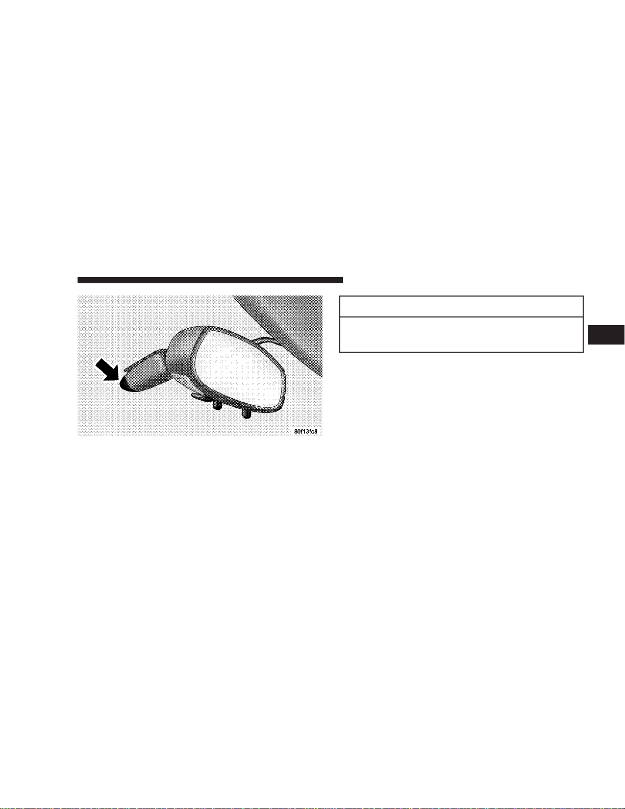
MIRRORS
Inside Day/Night Mirror
Adjust the mirror to center on the view through the rear
window. A pivot system allows for horizontal and vertical mirror adjustment.
Annoying headlight glare can be reduced by moving the
small control under the mirror to the night position
(toward rear of vehicle). The mirror should be adjusted
while set in the day position (toward windshield).
Electric Remote Control Mirrors
Both of the outside mirrors can be adjusted by using the
remote controls mounted inside the driver’s door, below
the door handle and power door switch.
3
Page 56

56 UNDERSTANDING THE FEATURES OF YOUR VEHICLE
NOTE: Place the mirror selector switch in the center
(neutral) position to prevent accidental movement of the
mirrors.
Mirror Adjustment
Outside Mirror — Driver’s Side
Adjust the outside mirror to center on the adjacent lane of
traffic, with a slight overlap of the view obtained on the
inside mirror.
Right Side Mirror
Adjust the convex outside mirror so you can just see the
side of your vehicle. This type of mirror will give a much
wider view to the rear, and especially of the lane next to
your vehicle.
WARNING!
Vehicles and other objects seen in the right side
convex mirror will look smaller and farther away
than they really are. Relying too much on your right
side mirror could cause you to collide with another
vehicle or other object. Use your inside mirror when
judging the size or distance of a vehicle seen in this
convex mirror.
Page 57

SEATS
Manual Front Seat Adjustments
The adjusting bar is at the front of the seats, near the floor.
Pull the bar up to move the seat to the desired position.
UNDERSTANDING THE FEATURES OF YOUR VEHICLE 57
Using body pressure, move forward and rearward on the
seat to be sure the seat adjusters have latched.
WARNING!
Adjusting a seat while the vehicle is moving is
dangerous. If you are driving, the sudden movement
of the seat could cause you to lose control. You could
be injured. Adjust any seat only while the vehicle is
parked. Do not ride with the seatback reclined so
that the shoulder belt is no longer riding against
your chest. In a collision you could slide under the
seat belt and be seriously or even fatally injured. Use
the recliner only when the vehicle is parked.
3
Reclining Seat
The recliner control is on the side of the seat on the
door-side. To recline, lean forward slightly before pulling
the lever, then lean back to the desired position, and
release the lever. Lean forward and pull the lever to
return the seatback to its original position.
Page 58

58 UNDERSTANDING THE FEATURES OF YOUR VEHICLE
To Open And Close The Hood
Two latches must be released to open the hood. First,
reach into the lower right grille opening and pull the
primary hood latch forward. Raise the front of the hood
slightly for access to the safety catch.
Then push the safety catch handle located under the front
edge of the hood toward the right. Raise the front of the
hood.
NOTE: Assist props will raise the hood to a normal
customer usage position. If greater access is required, the
Page 59

UNDERSTANDING THE FEATURES OF YOUR VEHICLE 59
hood may be pushed up at the front, raising the hood
beyond the initial opening height. Simply pull the hood
down to close it.
CAUTION!
Do not leave the hood open in areas where strong
gusts of wind are likely. Such a place might be by the
side of the road where large trucks pass by. Strong
gusts of wind may damage your hood. Always close
the hood in such situations.
WARNING!
If the hood is not fully latched, it could open when
the vehicle is moving and block your forward vision.
Be sure the hood latches are fully latched before
driving.
3
Page 60

60 UNDERSTANDING THE FEATURES OF YOUR VEHICLE
LIGHTS
Courtesy/Reading Lights
These lights, located under the rearview mirror, come on
whenever a door is opened or the illuminated entry
system is activated. The lights can also be turned on with
the doors closed by means of switches located on the
bottom of the rearview mirror. These lights also function
by rotating the dimmer control in the multi-function
control lever.
There are also courtesy lights located in both the driver
and passenger footwell areas. They will turn on as part of
the illuminated entry system by either opening a door,
unlocking the door from the remote keyless entry, or by
the multi-function control lever dimmer control.
Page 61

UNDERSTANDING THE FEATURES OF YOUR VEHICLE 61
Interior Lights
The interior lights come on when a door is opened and
the dome switch is not in the defeat position.
Battery Saver Feature — Interior Lights
The interior courtesy lights come on when a door is open
or left ajar. To prevent battery drain, if you leave a door
open or ajar, these lights will turn off after 15 minutes.
After you close the door, the interior courtesy lights will
again function in the normal manner.
Multi-Function Control Lever
The Multi-Function Control Lever controls the operation
of the headlights, parking lights, turn signals, headlight
beam selection, instrument panel light dimming, interior
lights, the passing lights, and fog lights. The lever is
located on the left side of the steering column.
Dimmer Control
With the parking lights or headlights
on, rotating the dimmer control for the
interior lights on the Multi-Function
Control Lever upward will increase
the brightness of the instrument panel
lights.
Dome Light Position
Rotate the dimmer control completely
upward to the second detent to turn
on the interior lights. The interior
lights will remain on when the dimmer control is in this position.
3
Page 62

62 UNDERSTANDING THE FEATURES OF YOUR VEHICLE
Interior Light Defeat (OFF)
Rotate the dimmer control to the extreme bottom “OFF” position. The interior lights will remain off when the
doors are open.
Parade Mode (Daytime Brightness Feature)
Rotate the dimmer control to the first
detent (white semi-circle). This feature
brightens the odometer and radio display when the parking lights or headlights are on during daylight conditions.
Headlights, Parking Lights, Instrument Panel
Lights, and Front Fog Lights
Turn the end of the Multi-Function Control Lever to the
first detent for parking light operation. Turn to the
second detent for headlight operation. Pull out the end of
the Multi-Function Control Lever to turn on the front fog
lights.
Page 63

UNDERSTANDING THE FEATURES OF YOUR VEHICLE 63
To change the brightness of the instrument panel lights,
rotate the center portion of the Multi-Function Control
Lever up or down.
Daytime Running Lights
The fog lights will come on as Daytime Running Lights
whenever the ignition switch is on, the headlights are off,
and the parking brake is off. The headlight switch must
be used for normal night time driving.
NOTE: This feature is standard on all Canadian vehicles
and cannot be disabled. For US vehicles, this feature is
shipped disabled and can be enabled (or disabled) at a
dealership if so desired.
Lights-On Reminder
If the headlights or parking lights are on after the ignition
is turned OFF, a chime will sound to alert the driver
when the driver’s door is opened.
Headlight Time Delay
This feature provides the safety of headlight illumination
for about 90 seconds.
To activate the delay, turn off the ignition while the
headlights are still on. Then turn off the headlights within
45 seconds. The delay interval begins when the headlamp
switch is turned off.
If the headlights are turned off before the ignition, they
will go off in the normal manner.
This feature can be disabled at the dealership if so
desired.
Battery Saver Feature — Exterior Lights
If an exterior light is left on when the ignition switch is
moved to the Off position (with the key in or out), it will
automatically turn off after 3 minutes. Normal operation
will resume when the ignition is turned On or when the
headlight switch is turned to another position.
3
Page 64

64 UNDERSTANDING THE FEATURES OF YOUR VEHICLE
If the ignition switch is turned to any position other than
the Off position at any time during the 3 minute delay
period the battery saver feature will be disabled.
Fog Lights
The front fog light switch is on the Multi-Function
Control Lever. To activate the front fog lights, turn
on the parking lights or the low beam headlights
and pull out the end of the control lever.
NOTE: The fog lights will only operate with the head-
lights on low beam. Selecting high beam headlights will
turn off the fog lights.
Turn Signals
Move the Multi-Function Control Lever up or down and
the arrows on each side of the instrument cluster flash to
show proper operation of the front and rear turn signal
lights. You can signal a lane change by moving the lever
partially up or down without moving beyond the detent.
Page 65

UNDERSTANDING THE FEATURES OF YOUR VEHICLE 65
If either light remains on and does not flash, or there is a
very fast flash rate, check for a defective outside light
bulb. If an indicator fails to light when the lever is
moved, it would suggest that the fuse or indicator bulb is
defective.
Highbeam/Lowbeam Select Switch
Pull the Multi-Function Control Lever towards you to
switch the headlights to HIGH beam. Pull the control
lever a second time to switch the headlights to LOW
beam.
Passing Light
You can signal another vehicle with your headlights by
lightly pulling the multi-function lever toward the steering wheel. This will cause the headlights to turn on at
high beam and remain on until the lever is released.
Tilt Steering Column
To tilt the column, simply pull down the small lever
below the turn signal control and move the wheel up or
down, as desired. Return the lever to the up position to
lock the wheel firmly in place.
3
Page 66

66 UNDERSTANDING THE FEATURES OF YOUR VEHICLE
WARNING!
Tilting the steering column while the vehicle is
moving is dangerous. Without a stable steering column, you could lose control of the vehicle and have
an accident. Adjust the column only while the vehicle is stopped. Be sure it is locked before driving.
ADJUSTABLE PEDALS
Your Viper is equipped with an adjustable pedal system
that allows about 4 inches (100 mm) of fore and aft pedal
adjustment. The pedals are adjusted using a switch
recessed into the knee bolster beneath the steering column.
To adjust the pedals:
•
Adjust the seat to a comfortable driving position.
•
Adjust the pedals to a position that allows full pedal
travel.
•
It may be necessary to make further small adjustments
to find the best possible seat/pedal position.
Page 67

UNDERSTANDING THE FEATURES OF YOUR VEHICLE 67
WARNING!
Do not adjust thepedals while the vehicle is moving.
You could lose control and have an accident. Always
adjust the pedals while the vehicle is parked.
Adjustable Left Foot Rest
3
The left foot rest can be manually adjusted fore and aft
and rotated up and down to a comfortable position.
Page 68

68 UNDERSTANDING THE FEATURES OF YOUR VEHICLE
To adjust the left foot rest:
•
Loosen the nut on the pedal using a 13 mm socket.
•
Slide the pedal fore, aft and/or rotate up or down to
find a comfortable position.
•
Retighten the nut, being careful not to overtighten.
WINDSHIELD WIPERS AND WASHERS
The wipers and washers are operated by a switch
in the right control lever. Move the control lever
up to select the desired wiper speed.
Page 69

UNDERSTANDING THE FEATURES OF YOUR VEHICLE 69
Windshield Washers
To use the washer, pull the control lever toward you and
hold while spray is desired. If the lever is pulled while in
the delay range, the wiper will operate in low speed for
two wipe cycles after the lever is released, and then
resume the intermittent interval previously selected.
If the lever is pulled while in the OFF position, the wipers
will operate for two wipe cycles, then turn OFF.
Mist Function
Push down on the wiper control lever to activate a single
wipe to clear the windshield of road mist or spray from
a passing vehicle. The wiper blade will continue to wipe
until you release the stalk.
Intermittent Wiper System
Use the intermittent wiper when weather conditions
make a single wiping cycle with a variable pause between cycles desirable. Move the lever to the first detent
(DEL) position, then select the delay interval by turning
the end of the stalk. Rotate the end upward to decrease
the delay time and downward to increase it. The delay
can be regulated from one second between cycles to 15
seconds between cycles.
3
Page 70

Page 71

UNDERSTANDING YOUR INSTRUMENT PANEL
CONTENTS
m Instrument Panel Features ..................73
m Instrument Cluster Description ..............74
▫ Speedometer ..........................74
▫ Turn Signal Indicators ...................75
▫ Hazard Indicator .......................75
▫ Message Center .......................75
▫ Gauges .............................80
m Electronic Digital Clock ...................81
▫ Clock Setting Procedure..................82
m Sales Code RBQ—AM & FM Stereo Radio With
6- Disc CD Changer ......................82
▫ Radio Operation .......................82
▫ CD Player Operation ....................85
m CD/DVD Disc Maintenance ................89
m Radio Antenna .........................90
m Radio Operation And Cellular Phones .........90
m Ventilation .............................90
m Climate Controls ........................90
4
Page 72

72 UNDERSTANDING YOUR INSTRUMENT PANEL
▫ Fan Control ..........................91
▫ Temperature Control ....................91
▫ Mode Control .........................91
▫ Operating Tips ........................94
Page 73

INSTRUMENT PANEL FEATURES
UNDERSTANDING YOUR INSTRUMENT PANEL 73
4
Page 74

74 UNDERSTANDING YOUR INSTRUMENT PANEL
INSTRUMENT CLUSTER DESCRIPTION
Speedometer
Shows the vehicle speed in miles-perhour and kilometers-per-hour.
Odometer/Trip Odometer
The odometer shows the total distance the vehicle has
been driven.
U.S. federal regulations require that upon transfer of
vehicle ownership, the seller certify to the purchaser the
correct mileage that the vehicle has been driven. Therefore, if the odometer reading is changed, during repair or
replacement, be sure to keep a record of the reading
before and after the service so that the correct mileage can
be determined.
The trip odometer shows individual trip mileage. To
switch from odometer to trip odometer, press and release
the Trip Odometer button. Press and release the Trip
button a second time to return to the odometer. While in
trip mode, press and hold the button for at least 1 second
to reset the trip odometer to zero.
Door Unlocked, Door Ajar, Low Tire Warnings
If you move the vehicle and a door is not completely
closed, the words DOOR AJAR will appear in the display
and a chime will sound once. If the door is not locked,
DOOR UNLOCK will appear in the display. If the tire
pressure is low, the words LOW TIRE will appear in the
display and a chime will sound once.
Page 75

UNDERSTANDING YOUR INSTRUMENT PANEL 75
Turn Signal Indicators
The arrows will flash in unison with the corresponding
exterior turn signal when using the signal lever.
Hazard Indicator
Both turn signal arrows will flash in unison with all front
and rear turn signals when the hazard warning switch is
used.
NOTE: Leaving the hazard flashers on for extended
periods of time will wear down the battery.
Message Center
Message Center Components
Anti-Lock Warning Light
The amber ABS Warning Light will come on when
the ignition is first turned on, and stay on briefly
as a bulb check. If the bulb does not come on during
starting, have the bulb repaired promptly. This light also
illuminates to indicate that the Antilock Brake System
self-check is in process at vehicle start-up. If the light
remains on after start-up, or comes on and stays on at
road speeds, it may indicate that the ABS has detected a
malfunction or has become inoperative. In this case, the
system reverts to standard non-antilock brakes. Turn the
engine off and on again to reset the Antilock Brake
System. If the light remains on, see your authorized
dealer. If both the red BRAKE and amber ABS warning
lights are on and the parking brake is fully released, see
your authorized dealer immediately.
4
Page 76

76 UNDERSTANDING YOUR INSTRUMENT PANEL
WARNING!
If both ABS and/or Brake Warning lamps become
illuminated, please seek service immediately! Your
Viper will have diminished braking capability and
control if ABS and/or service brake systems are not
working properly. Have your brake system serviced
immediately.
Skip Shift Indicator
This indicator is located in the Tachometer. There
are two LED lights. The amber LED light will come
on when you arebeing prevented from shifting from First
to Second or Thirdgear. The tachometer’s shift arrow also
houses a red LED light that activates when the tachometer gauge pointer goes above 5600 RPM and it shuts off
when the tachometer pointer falls below 5500 RPM. The
indicator serves as a visual aid to shift before reaching the
red line.
Malfunction Indicator Light
This light is part of an onboard diagnostic
system called OBD II which provides in-field
emissions inspection tests required in some
states. If certain self-diagnostic monitors are
not complete, the light starts flashing 14 seconds after the
key is switched on and will continue to flash for approximately 11 seconds. If the OBD II monitors have completed, the malfunction indicator lamp will not flash as
described above.
The light will illuminate when the key is turned to the
ON position before engine start. The light will remain on
steady until the engine has started. If the bulb does not
come on when turning the key from OFF to ON have the
condition checked promptly. The light will turn off after
the engine has started, unless a malfunction is present.
Page 77

UNDERSTANDING YOUR INSTRUMENT PANEL 77
CAUTION!
Prolonged driving with the light on could cause
further damage to the emission control system. It
could also affect fuel economy and driveability. The
vehicle must be serviced before any state emissions
tests can be performed.
If the light is flashing, severe catalytic converter damage
and power loss will soon occur. Immediate service is
required.
If the gas cap is not secured properly, the light may come
on. Be sure the gas cap is tightened every time you add
fuel.
High Beam Indicator
This light shows that the headlights are on high
beam. Pull the turn signal lever toward the steering wheel to switch the headlights from high or low
beam.
Seat Belt Indicator Light
This system alerts the driver to fasten the seat belt
if not done so within 60 seconds of starting the
vehicle and if the vehicle is moving faster than 5
mph (8 km/h). The system will cause a chime to sound
repeatedly and will flash the seat belt warning light for 96
seconds or until the driver’s seat belt is fastened. The
reminder system will be reactivated if the driver’s seat
belt is unfastened for more than 10 seconds and the
vehicle speed is greater than 5 mph (8 km/hr). Refer to
Enhanced Seat Belt Use Reminder System (BeltAlert™) in
the Occupant Restraints section for deactivating the
system.
4
Page 78

78 UNDERSTANDING YOUR INSTRUMENT PANEL
Trunk Ajar Light
This light indicates that the trunk is not latched.
Engine Coolant Temperature Light
A red LED light on the Coolant Temperature
gauge will illuminate to warn of an overheated
engine coolant condition.
Low Oil Pressure Light
A red LED light on the Oil Pressure gauge will
illuminate to indicate low engine oil pressure. The
light should come on briefly as a bulb check when the
engine is first started. If the light stays on or comes on
while driving, stop the vehicle and shut off the engine.
DO NOT operate the vehicle until the cause is corrected.
NOTE: This light does not indicate how much oil is in
the engine. The engine oil level must be checked under
the hood.
Charge System Light
A red LED light on the Voltage gauge will illuminate when there is a charging system malfunction
or a possible accessory drive belt failure.
CAUTION!
The accessory belt also drives the water pump.
Operating the vehicle with a failed belt can cause
engine overheating and possible severe engine damage.
Fog Light ON Indicator
This light indicates that the fog lights are on.
Page 79

UNDERSTANDING YOUR INSTRUMENT PANEL 79
Brake System Warning Light
The dual brake system provides a reserve
braking capability in the event of a failure to a
portion of the hydraulic system. The warning
light should be checked frequently to assure
that it is operating properly. This can be done by turning
the ignition switch to a point midway between ON and
START.The light should come on. The red Brake Warning
Light will come on when the ignition is first turned on,
and stay on briefly as a bulb check. If the bulb does not
come on during starting, have the bulb repaired
promptly. If the light stays on longer, it may be an
indication that the parking brake has not been released. If
the light remains on when the parking brake is off it
indicates a possible brake hydraulic system malfunction.
Immediate repair is necessary and continued operation of
the vehicle in this condition is dangerous.
WARNING!
Driving a vehicle with the brake light on is dangerous. Part of the brake system has failed. It will take
longer to stop the vehicle. You could have a accident.
Have the brakes checked immediately.
Airbag Light
This light will come on and remain on for 6 to
8 seconds as a bulb check when the ignition
switch is first turned on. If the bulb is not lit
during starting, have it replaced. If the light
stays on or comes on while driving, have the system
checked by an authorized dealer.
4
Page 80

80 UNDERSTANDING YOUR INSTRUMENT PANEL
Gauges
Tachometer
This gauge shows engine speed in revolutionsper-minute (RPM) times 1,000. Avoid excessive
engine speeds in any part of the red warning
zone, particularly when driving downhill or in
lower gears.
Coolant Temperature Gauge
This gauge shows the engine coolant temperature. The gauge pointer will likely show higher
temperatures when driving in hot weather, up
mountain grades, or in heavy stop and go
traffic. If the red LED light turns on, stop the vehicle and
turn off the engine until the cause is corrected.
Oil Temperature Gauge
This gauge shows the oil temperature. The
gauge pointer will likely show higher temperatures when driving in hot weather, up moun-
tain grades, or in heavy stop and go traffic. If
the red LED light turns on, stop the vehicle and turn off
the engine until the cause is corrected.
Oil Pressure Gauge
This gauge shows engine oil pressure when the
engine is running. The pressure will vary with
engine speed, oil viscosity, and engine tem-
perature. Oil pressures will be higher as the
engine is warming up. The normal operating pressure is
between 20 and 80 psi (pounds per square inch). If the
pointer remains in the red range, turn off the engine until
the cause is corrected.
Page 81

UNDERSTANDING YOUR INSTRUMENT PANEL 81
This gauge does not indicate the amount of oil in the
engine. The engine oil level must be checked under the
hood. Check the level often during severe usage.
Fuel Gauge
This gauge shows the amount of fuel in the gas
tank. The reaction time of the gauge has been
slowed to avoid needle fluctuation during periods of high G force cornering.
Voltage Gauge
This gauge shows the electrical system voltage.
The normal operating voltage is from 12 to 14
volts with the engine running. If the pointer
remains at either the high or low ends of the
scale, the electrical system should be serviced.
ELECTRONIC DIGITAL CLOCK
The clock and radio each use the display panel built into
the radio. A digital readout shows the time in hours and
minutes whenever the ignition switch is in the ON or
ACC position.
When the ignition switch is in the OFF position, or when
the radio frequency is being displayed, time keeping is
accurately maintained.
Press and release the Time button to display the time.
Press and release the button a second time to turn off the
time display.
4
Page 82

82 UNDERSTANDING YOUR INSTRUMENT PANEL
Clock Setting Procedure
1. Turn the ignition switch to the “ON” or “ACC”
position. Using the point of a ballpoint pen or similar
object, press either the “H” (Hour) or “M” (Minute)
buttons on the radio. The display will show the time.
2. Press the “H” button to set hours or the “M” button to
set minutes. The time setting will increase each time you
press a button.
SALES CODE RBQ—AM & FM STEREO RADIO
WITH 6- DISC CD CHANGER
Radio Operation
Power/Volume Control
Press the PWR/VOL control to turn the radio on. Turn
the volume control clockwise to increase the volume.
Page 83

UNDERSTANDING YOUR INSTRUMENT PANEL 83
NOTE: Power to operate the radio is controlled by the
ignition switch. It must be in the ON or ACC position to
operate the radio.
Mode
Press the MODE button repeatedly to select between AM,
FM, and the CD changer.
Seek
Press and release the SEEK button to search for the next
station in either the AM or FM mode. Press the top of the
button to seek up and the bottom to seek down. The
radio will remain tuned to the new station until you
make another selection. Holding the button in will bypass stations without stopping until you release it.
Tune
Press the TUNE control up or down to increase or
decrease the frequency. If the button is pressed and held,
the radio will continue to tune until the button is
released. The frequency will be displayed and continuously updated while the button is pressed.
Balance — BAL
The Balance control adjusts the left-to-right speaker balance. Press the BAL button in and it will pop out. Adjust
the balance and push the button back in.
Fade
The Fade control provides for balance between the front
and rear speakers. Press the FADE button in and it will
pop out. Adjust the balance and push the button back in.
Tone Control
The tone controls affect the Bass and Treble frequency
bands. Each is controlled by a slider control with a detent
at the mid position. Moving a control up or down
increases or decreases amplification of the band. The mid
position provides a nominal frequency response.
4
Page 84

84 UNDERSTANDING YOUR INSTRUMENT PANEL
To Set The Radio Push-Button Memory
When you are receiving a station that you wish to
commit to push-button memory, press the SET RND
button. SET 1 will show in the display window. Select the
“1–5” button you wish to lock onto this station and press
and release that button. If a button is not selected within
5 seconds after pressing the SET RND button, the station
will continue to play but will not be locked into pushbutton memory.
You may add a second station to each push-button by
repeating the above procedure with this exception: Press
the SET button twice and SET 2 will show in the display
window. Each button can be set for SET 1 and SET 2 in
both AM and FM. This allows a total of 12 AM and 12 FM
stations to be locked into push-button memory. The
stations stored in SET 2 memory can be selected by
pressing the corresponding push-button twice. Every
time a preset button is used, a corresponding button
number will be displayed.
To Change From Clock To Radio Mode
Press the TIME button to change the display between
radio frequency and time.
General Information
This radio complies with Part 15 of FCC rules and with
RSS-210 of Industry Canada. Operation is subject to the
following conditions:
1. This device may not cause harmful interference,
2. This device must accept any interference received,
including interference that may cause undesired operation.
NOTE: Changes or modifications not expressively approved by the party responsible for compliance could
void the user’s authority to operate the equipment.
Page 85

UNDERSTANDING YOUR INSTRUMENT PANEL 85
CD Player Operation
NOTE: The ignition switch must be in the ON or ACC
position and the Power / Volume control pushed ON
before the CD player will operate.
Inserting The Compact Disc
CAUTION!
This CD player will accept 43⁄4inch (12cm) discs
only. The use of other sized discs may damage the
CD player mechanism.
You may either insert or eject a disc with the radio OFF.
If you insert a disc with the ignition ON and the radio
OFF, the display will show the time of day. If you insert
a disc with the ignition OFF, the display will show the
time of day for about 5 seconds, then go out.
If the power is ON, the unit will switch from radio to CD
mode and begin to play when you insert the disc. The
display will show the track number and index time in
minutes and seconds. Play will begin at the start of track 1.
LOAD/ EJT — Load
Press the LOAD/ EJT button and the button with the
corresponding number where the CD is being loaded.
After the radio displays “load” insert the CD into the
player.
Radio display will show “loading” when it is being
loaded.
LOAD / EJT — Eject
Press the LOAD/ EJT button and the button with the
corresponding number where the CD was loaded and the
disc will unload and move to the entrance for easy
removal. The unit will switch to the radio mode.
4
Page 86

86 UNDERSTANDING YOUR INSTRUMENT PANEL
Radio display will show “ejecting” when it is being
ejected.
If you have ejected a disc and have not removed it within
15 seconds, it will be reloaded. The unit will continue in
radio mode.
The disc can be ejected with the radio and ignition OFF.
Seek
Press the top of the SEEK button for the next selection on
the CD. Press the bottom of the button to return to the
beginning of the current selection, or return to the
beginning of the previous selection if the CD is within the
first second of the current selection.
Scan
Press the Scan button to scan through each track on the
CD currently playing.
FF/TUNE/RW
Press FF (Fast Forward) and the CD player will begin to
fast forward until FF is released. The RW ( Reverse)
button works in a similar manner.
Random Play — SET / RND
Press the RND button while the CD is playing to activate
Random Play. This feature plays the selections on the
compact disc in random order to provide an interesting
change of pace.
Press the SEEK button to move to the next randomly
selected track.
Press TUNE FF to fast forward through the tracks. Press
the FF button a second time to stop the fast forward
feature. If TUNE RW is pressed, the current track will
reverse to the beginning of the track and begin playing.
Press the SET / RND button a second time to stop
Random Play.
Page 87

UNDERSTANDING YOUR INSTRUMENT PANEL 87
CD Diagnostic Indicators
When driving over a very rough road, the CD player may
skip momentarily. Skipping will not damage the disc or
the player, and play will resume automatically.
As a safeguard and to protect your CD player, one of the
following warning symbols may appear on your display.
A “CD HOT” symbol indicates that player is too hot. In
this case, the CD player will switch to the radio mode.
Play can be resumed when the operating temperature is
corrected.
The “ERROR” symbol will appear on the display if the
laser is unable to read the disc data for the following
reasons:
•
Excessive vibration
•
Disc inserted upside down
•
Damaged disc
•
Water condensation on optics
PTY (Program Type) Button
Pressing this button once will turn on the PTY mode for
5 seconds. If no action is taken during the 5 second time
out the PTY icon will turn off. Pressing the PTY button
within 5 seconds will allow the program format type to
be selected. Many radio stations do not currently broadcast PTY information.
4
Page 88

88 UNDERSTANDING YOUR INSTRUMENT PANEL
Toggle the PTY button to select the following format types:
Program Type Radio Display
Adult Hits Adlt Hit
Classical Classicl
Classic Rock Cls Rock
College College
Country Country
Information Inform
Jazz Jazz
Foreign Language Language
News News
Nostalgia Nostalga
Oldies Oldies
Personality Persnlty
Public Public
Rhythm and Blues R & B
Religious Music Rel Musc
Program Type Radio Display
Religious Talk Rel Talk
Rock Rock
Soft Soft
Soft Rock Soft Rck
Soft Rhythm and Blues Soft R&B
Sports Sports
Talk Talk
Top 40 Top 40
Weather Weather
By pressing the SEEK button when the PTY icon is
displayed, the radio will be tuned to the next frequency
station with the same selected PTY name. The PTY
function only operates when in the FM mode.
Page 89

UNDERSTANDING YOUR INSTRUMENT PANEL 89
The radio display will flash “SEEK” and the selected PTY
program type when searching for the next PTY station. If
no station is found with the selected PTY program type,
the radio will return to the last station.
If a preset button is activated while in the PTY (Program
Type) mode, the PTY mode will be exited and the radio
will tune to the preset station.
By pressing the SCAN button when the PTY icon is
displayed, the radio will stop at every PTY station on the
band and list each corresponding program type in the
radio display.
Time
Press the TIME button to change the display from
elapsed CD playing time to time of day.
CD/DVD DISC MAINTENANCE
To keep the CD/DVD discs in good condition, take the
following precautions:
1. Handle the disc by its edge; avoid touching the
surface.
2. If the disc is stained, clean the surface with a soft cloth,
wiping from center to edge.
3. Do not apply paper, paper CD labels, or tape to the
disc; avoid scratching the disc.
4. Do not use solvents such as benzine, thinner, cleaners,
or antistatic sprays.
5. Store the disc in its case after playing.
6. Do not expose the disc to direct sunlight.
7. Do not store the disc where temperatures may become
too high.
4
Page 90

90 UNDERSTANDING YOUR INSTRUMENT PANEL
RADIO ANTENNA
The radio antenna is located in the windshield.
RADIO OPERATION AND CELLULAR PHONES
Under certain conditions, the operation of a cellular phone
in your vehicle can cause erratic or noisy performance from
your radio. This condition may be lessened or eliminated
by relocating the cellular phone antenna. This condition is
not harmful to the radio. If your radio performance does
not satisfactorily “clear” by the repositioning of the antenna, it is recommended that the radio volume be turned
down or off during cellular phone operation.
VENTILATION
When the ventilation mode is selected, outside air comes
through the panel outlets. Air will enter the vehicle with
or without the blower in operation.
CLIMATE CONTROLS
The Air Conditioning System allows you to balance the
temperature, amount and direction of the air circulating
throughout the vehicle.
Page 91

UNDERSTANDING YOUR INSTRUMENT PANEL 91
The controls are as follows:
Fan Control
Use this control to regulate the
amount of air forced through the system in any mode you select. Turn the
control clockwise to increase fan
speed. Turn the control to theO—Off
position to shut off the fan and to
prevent any outside air from entering
the vehicle. This also turns off the A/C compressor.
Temperature Control
Use this control to regulate the temperature of the air inside the passenger compartment. The blue area of the
control indicates cooler temperatures
while the red area indicates warmer
temperatures.
Mode Control
Use this control to select the direction
of air flow.
4
NOTE: The dot between the mode control icons is a mix
position between the two modes.
The mode control positions are as follows:
Recirculate
Air is recirculated inside the vehicle. You may
choose between Bi-Level and Panel air outlets
while in this mode. Use this mode to tempo-
rarily block out any outside odors, smoke, or
dust and to cool the interior rapidly upon initial start up
in very hot or humid weather.
Page 92

92 UNDERSTANDING YOUR INSTRUMENT PANEL
Panel
Air is directed through the outlets in the instrument
panel. These outlets can be adjusted to direct air
flow.
Bi-Level
Air is directed through the instrument panel and
floor outlets. A small amount of air is also directed
through the defrost outlets.
NOTE: There is a varying temperature differential be-
tween the upper and lower outlets for added comfort.
The warmer air goes to the floor outlets. This feature
provides improved comfort during sunny but cool conditions.
Floor
Air is directed through the floor outlets with a
lesser amount through the defrost outlets.
Floor/Defrost
Air is directed through the windshield defrost and
the floor outlets. This setting works best in cold or
snowy conditions that require extra heat at the
windshield. This setting is good for maintaining comfort
while reducing moisture on the windshield.
Windshield Defrost
Air is directed through the windshield defrost
outlet. Use this mode with maximum fan and
temperature settings for best windshield defrosting.
NOTE: The air conditioning compressor operates in this
mode. This dehumidifies the air to help dry the windshield. To improve fuel economy, leave in the Defrost
mode only when necessary.
A/C Pushbutton
With the fan control in the ON position, pushing
the A/C button turns on the air conditioning
compressor. An indicator light above the button
Page 93

UNDERSTANDING YOUR INSTRUMENT PANEL 93
shows that the Air Conditioning compressor is on. Conditioned air is now directed through the outlets selected.
Pushing the button a second time turns the compressor
OFF.
Slight changes in engine speed or power may be noticed
when the compressor is on. This is a normal occurrence
since the compressor will cycle on and off to maintain
comfort and increase fuel economy.
NOTE: If your air conditioning performance seems
lower than expected, check the front of the A/C condenser for an accumulation of dirt or insects.
Rear Window Defroster
Press the button once to turn on the Rear Window
Defroster and a second time to turn it off. A light
above the button shows that the Rear Defroster is On.
NOTE: The defroster turns off automatically after 15
minutes of operation. Each later activation will allow 7
1
minutes of operation.
CAUTION!
To avoid damaging the electrical conductors, do not
use scrapers, sharp instruments, or abrasive window
cleaners on the interior surface of the rear window.
Labels can be peeled off by soaking with warm
water.
⁄
2
4
Page 94

94 UNDERSTANDING YOUR INSTRUMENT PANEL
Operating Tips
When operating the system during the winter months,
make sure the air intake, at the right side of the hood, is
free of ice, slush, snow or other obstructions such as
leaves. Leaves collected in the air-intake plenum may
reduce air flow and plug the plenum water drains.
The blower air will heat faster in cold weather if you use
only the low blower speeds for the first ten minutes of
vehicle operation.
During engine warm-up in cold weather, use the Defrost
mode to direct any cold air away from the occupants.
Page 95

CONTENTS
STARTING AND OPERATING
m Starting Procedures ......................97
▫ If Engine Fails To Start ..................98
▫ After Starting ........................100
m Transmission Shifting ....................100
▫ Recommended Shift Speeds ..............101
▫ Skip Shift Light .......................101
m Parking Brake .........................102
m Brake System ..........................104
▫ Brake Pad Break-In ....................107
m Power Steering ........................107
m Tire Safety Information ...................108
▫ Tire Markings ........................108
▫ Tire Identification Number (TIN) ..........111
▫ Tire Loading And Tire Pressure ...........112
m Tires—General Information ................116
▫ Tire Pressure .........................116
▫ Tire Inflation Pressures .................117
▫ Radial-Ply Tires ......................120
5
Page 96

96 STARTING AND OPERATING
▫ Compact Spare Tire — If Equipped .........120
▫ Tire Spinning ........................121
▫ Tread Wear Indicators ..................122
▫ Replacement Tires .....................122
▫ Alignment And Balance .................123
m Low Tire Pressure (Ltp) System .............124
▫ Low Tire Indicator ....................124
m Tire Chains ...........................125
m Snow Tires ...........................125
m Tire Storage ...........................126
m Tire Rotation Recommendations ............126
m Ground Clearance ......................126
m Fuel Requirements ......................127
▫ Reformulated Gasoline .................127
▫ Gasoline/Oxygenate Blends ..............128
▫ MMT In Gasoline .....................128
▫ Sulfur In Gasoline .....................129
▫ Materials Added To Fuel ................129
m Adding Fuel ..........................129
m Vehicle Loading ........................130
m Trailer Towing .........................130
Page 97

STARTING PROCEDURES
CAUTION!
Long periods of engine idling, especially at high
engine speeds, can cause excessive exhaust temperatures which can damage your vehicle. Do not leave
your vehicle unattended with the engine running.
WARNING!
Do not leave animals or children inside parked
vehicles in hot weather; interior heat build up may
cause serious injury or death.
Fully apply the parking brake, press the clutch pedal to
the floor, and place the gear selector in NEUTRAL before
starting the engine.
STARTING AND OPERATING 97
5
NOTE: The engine will not start unless the clutch pedal
is pressed to the floor.
Normal Starting of either a cold or a warm engine does
not require pumping or depressing the accelerator pedal.
To start the vehicle, turn the key to the ON position and
press the red ENGINE START button located on the
instrument panel and release when the engine starts. If
Page 98

98 STARTING AND OPERATING
the engine has not started within 3 seconds, slightly
depress the accelerator pedal while continuing to crank.
If the engine fails to start within 10 seconds, turn the key
to the “OFF” position, wait 5 seconds, then repeat the
normal starting procedure.
If Engine Fails to Start
NOTE: The Remote Keyless Entry Transmitter MUST be
used to unlock the vehicle and disarm the alarm system.
In the event of a lost or defective Remote Keyless
Transmitter, the security system can be momentarily
disarmed to allow the vehicle to be started.
See the paragraph on the Vehicle Theft Security System in
Section 2 of this manual
Page 99

STARTING AND OPERATING 99
WARNING!
Do not attempt to push or tow your vehicle to get it
started. Unburned fuel could enter the catalytic
converter and once the engine has started, ignite and
damage the converter and vehicle. If the vehicle has
a discharged battery, booster cables may be used to
obtain a start from a booster battery or the battery in
another vehicle. This type of start can be dangerous
if done improperly, so follow this procedure carefully. See section 6 of this manual for jump starting
instructions.
If the engine fails to start after you have followed the
“NORMAL STARTING” procedure, it may be flooded.
Push the accelerator pedal all the way to the floor and
hold it there while cranking the engine. This should clear
any excess fuel in case the engine is flooded.
NOTE: To prevent damage to the starter, do not crank
the engine for more than 15 seconds at a time. Wait 10 to
15 seconds before trying again.
If the engine has been flooded, it may start to run, but not
have enough power to continue running when the start
button is released. If this occurs, continue cranking with
the accelerator pedal pushed all the way to the floor.
Release the accelerator pedal and the start button once
the engine is running smoothly.
If the engine shows no sign of starting after two 15
second periods of cranking with the accelerator pedal
held to the floor, the “NORMAL STARTING” procedure
should be repeated.
5
Page 100

100 STARTING AND OPERATING
After Starting
The idle speed will automatically decrease as the engine
warms up.
WARNING!
Never pour fuel or other flammable liquid into the
throttle body air inlet opening in an attempt to start
the vehicle. This could result in flash fire causing
serious personal injury.
TRANSMISSION SHIFTING
NOTE: The parking brake should be engaged and the
gear selector placed in REVERSE before leaving the
vehicle, especially on an incline.
Fully depress the clutch pedal before you shift gears. As
you release the clutch pedal, lightly depress the accelerator pedal.
Be sure the transmission is in FIRST gear, (not THIRD),
when starting from a standing position. Damage to the
clutch can result from starting in THIRD.
For most city driving you will find it easier to use only
the lower gears. For steady highway driving with light
accelerations, 6th gear is recommended.
Never drive with your foot resting on the clutch pedal, or
try to hold the vehicle on a hill with the clutch pedal
partially engaged. This will cause abnormal wear on the
clutch.
Never shift into REVERSE until the vehicle has come to a
complete stop.
NOTE: During cold weather, until the transmission
lubricant has warmed, you may have difficulty shifting.
This is normal and not harmful to the transmission.
 Loading...