

Page 1
CHRONOMITE INSTANT-FLOW WATER HEATER
INSTALLATION AND OPERATION INSTRUCTIONS - (LOW FLOW MODELS)
(Before installation, compare electrical needed for the model of heater selected)
TABLE 1
Instant-Flow
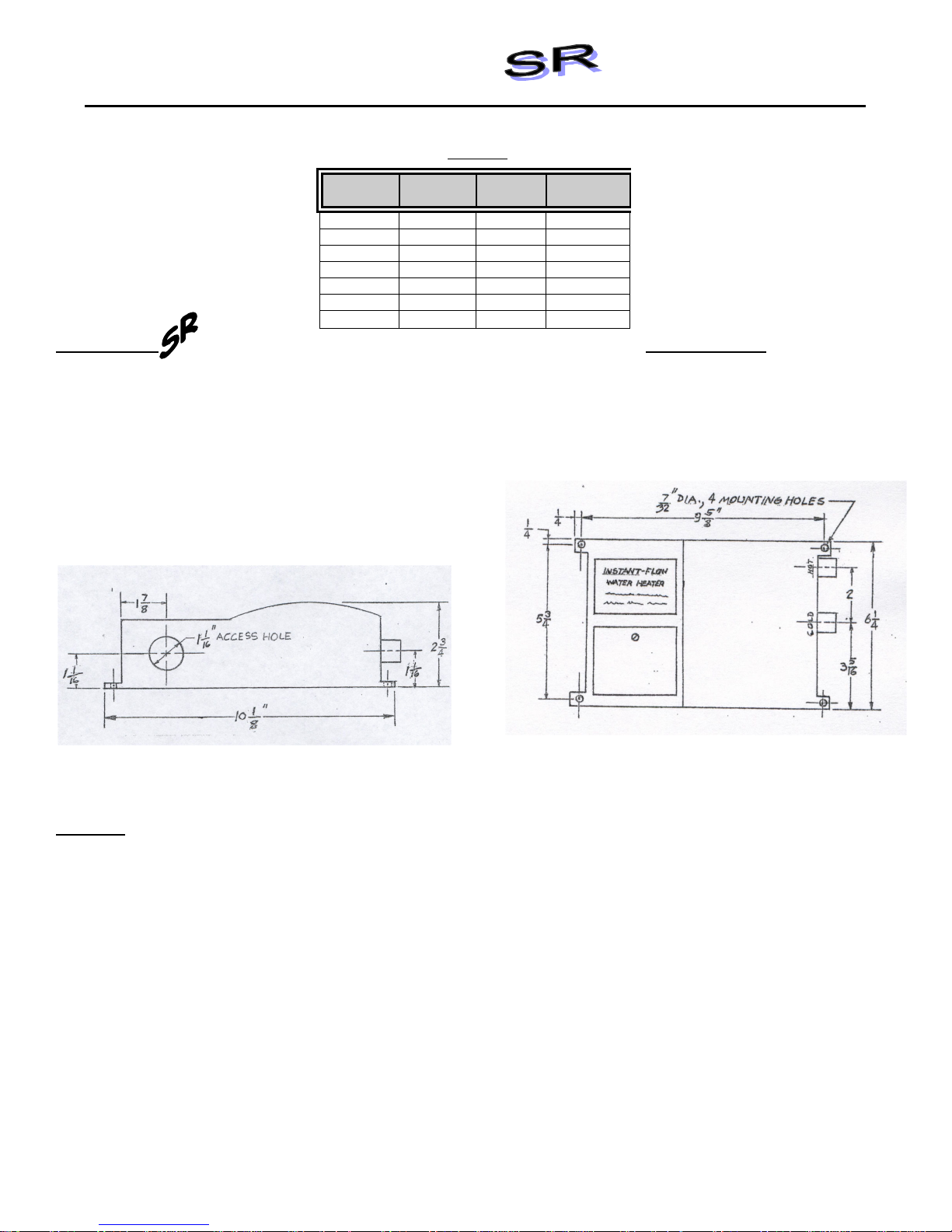
• Dimensions: 6¼” x 9 5/8” x 2 ¾”
• Weight: 5 lbs.
• Materials: Rugged cast aluminum alloy casing, Celcon wat er w ay s, nichrome parts
• Color: White (unless stainless steel housing)
• Pipe Fittings: Female ¼” NPT standard pipe thread
• Pressure Requirements: 25 PSI Minimum, 150 PSI Maximum (300 PSI tested) No pressure relief valve needed
• Maximum Operating Temp: 140°F
• Flow Switch Activation: .4 GPM
• Flow Switc h De-A c tivation: .35 GPM
• Listings: UL, HUD, IAPMO
THE MANUFACTURER OF THIS WATER HEATER WILL NOT BE LIABLE FOR ANY DAMAGES
DUE TO THE FAILURE TO FOLLOW THESE INSTALLATION AND OPERATION INSTRUCTIONS.
CAUTION: BEFORE BEGINNING THE INST ALLATION:
1. Remove electrical access cover. Attach conduit to the conduit access hole. Then feed wires. Do not attach wiring.
2. Mount unit horizontally against the wall so the silver label reads corr ectly (See Fig. 1). M ount with four screws
through the flanges located on each corner using molly anchors or fasteners.
CAUTION: Heating elements may burn out if unit is not mounted horizontally.
3. Connect plumbing. Use ¼” taper ed national pipe thread at c old w at er inlet and hot water outlet (See Fig. 1). Use
compression fittings supplied for ease of installation. Do not apply heat to these fitt ings.
4. Run water through the unit to expel all air bubbles. Check for leaks at all fitting joints.
5. Connect wiring. Attach ground wire to center terminal and hot wires to outer terminals (See Fig. 3)
6. Replace electrical access cover. Turn on the circuit breaker. The unit is now ready for use.
7. Local plumbing and electrical codes must be f ollowed in the installation of this water heater and it’s accessories.
8. Failure t o comply wit h code requirements voids the warranty.
9. Failure to insta ll faucet flow c o nt r o l a s s how n on Fig. 2 will cause unsatis fact o ry ope r a tion of the heater .
Specifications:
unless required by local codes.
A) Turn off the circuit breaker to avoid dangerous electrical shocks.
B) Turn off the water supply.
Model No. Wattage Voltage Breaker
Size
SR-15L 1800 110/120 15A
SR-15L 4150 277 15A
SR-20L 2400 110/120 20A
SR-20L 4160 208 20A
SR-20L 4800 220/240 20A
SR-20L 5540 277 20A
SR-30L 3600 110/120 30A
Page 2
IMPORTANT NOTES:
1. Turn off elect r ical supply – open circuit breaker .
2. Turn on water supply.
3. Expel all air from lines and heater.
4. Turn on electrical power supply – close circuit breaker.
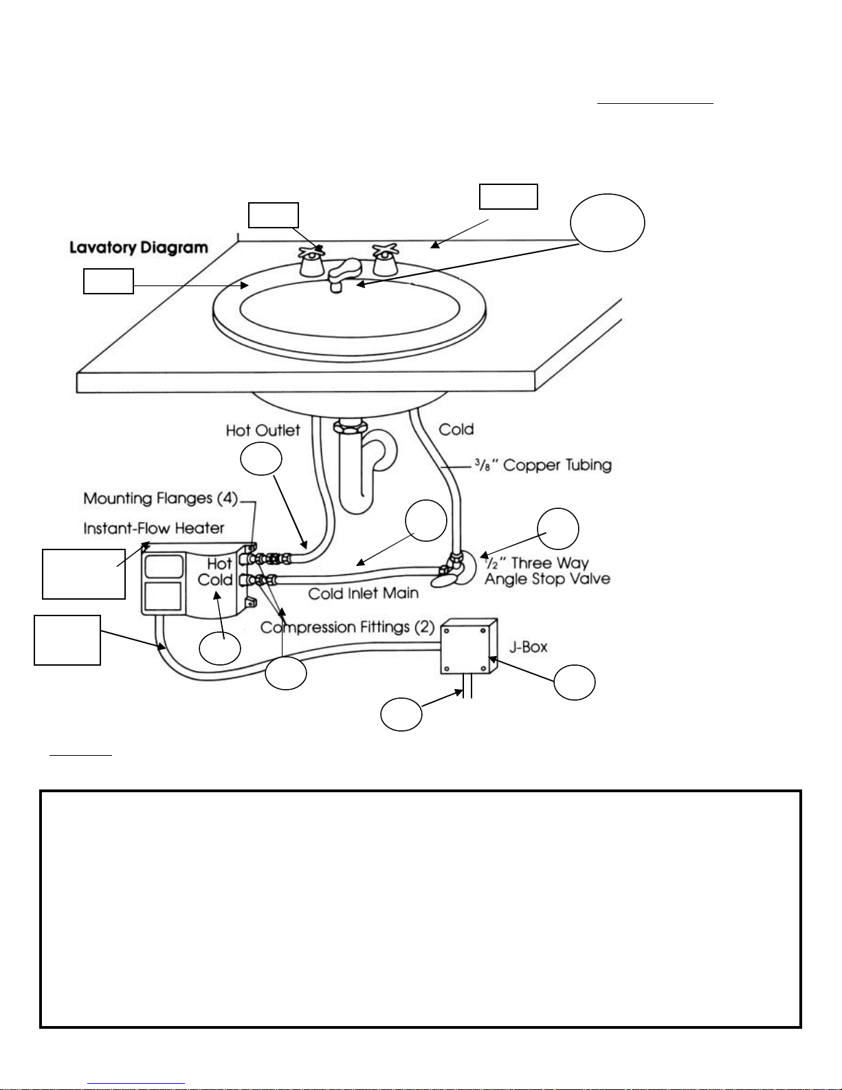
Sink
Air in the heater may cause the elements to burn out. If the water lines are drained,
allowing air into the heater, be sure to follow the following start-up procedure:
Hot
#8
Cold
#9 , #10
#7
Mounting
Flange
#3
Conduit
FIGURE 1 HEATER INSTALLATION
Faucet flow controls must be att ached to the faucet to allow the water heating system to operate more effectively
(See Fig. 2, pg. 3 for installation).
Item Part No. Names Qty Description
1. SR-_ _L Chronomite I nstant-Flow SR Heater 1 Models shown in Table 1
2. Electrical junction box
3. Electrical conduit ½” conduit, length as required
4. Electrical wire Electrical Wire
5. Dual outlet angle valve 1 ½” FPx7/16” comp.x3/8 comp., Br ass
Craft P/N R2701R-RGH
6. Fitting (supplied) 2 3/8” comp x ¼”MP
7. Copper or flex tubing 1 3/8” O D, 5” long (keep short)
8. Copper or flex tubing 3/8” OD, length as required (keep short)
9. L-412 Faucet flow control, dual thread 1 Supplied w ith Low Flow Heater
OR (see figure #2) SR-15L, SR-20L, SR-30L
10. LP-412 Faucet f low control, dual thread 1 Supplied wit h Low Flow Heater
#1
#6
#4
#5
#2
Page 3

SR-15L, SR-20L, SR-30L
Note: MP=Male Pipe FP= female Pipe Comp=Compression Fittings
(page 2)
OPERATION INSTRUCTIONS
Turn the hot water fixture to activate the flow switch. The flow switch activates at .4 gallons per minute (GPM) and
deactivates at .35 gallons per minute (GPM) .
If you increase the flow rate of the water above .5 GPM t he wat er t emperat ure w ill be c o me c o ole r. Cold wate r can alw ay s
be mixed just as with a conventional system if using a two handle faucet.
Once y ou dec rease the flow rate to .3 5 GPM t he unit w ill deact ivate. I t is not advisable to operat e t he heaters at . 35
GPM.
>Periodically inspect t he supply lines, connections and heater f or any moisture, corrosion or other potential preventable
problems.
HOW INSTANT-FLOW SR WORKS
The cast alloy case houses a series of ingeniously designed coils that instantly heat wat er as it f low s through the vessel. A
unique power switch automatically applies electr ical current to the coils when hot wat er is requested. The electrical current
is not applied when the water is not in use.
FLOW CONTROL SPECIFI CATI ONS
Mater ial: Chrome plated, br ass housing.
Threading: MO DEL L-412 & LP-212 has male/female threads for f aucets
with 15/16” f emale or 55/64” male threads.
*Flow controls are adapt able t o ot her thread configurations.
Please call factory I f adapt er is needed.
FLO W CONTROL MODELS
Model GPM Vandal Proof M odels GPM
L-412 (Dual) 0.5 L-910VR (Female) 0.5
LP-412 (Dual) 0.5 L-910VR (Female) 1.0
FIGURE 2
FLOW CONTROL INSTALLATIO N (See Parts List #9 & #10)
Page 4

(page 3)
TEMPERATURE INCREASE ABOVE INCOMING WATER TEMPERATURE
MODEL VAC
0.4 GPM 0.5 GPM
operatin g f low rat e
Hot or
Hot or
SR-15L 110/120 30°F 24°F
SR-15L 277 71°F 57°F
SR-20L 110/120 41°F 33°F
SR-20L 208 71°F 57°F
SR-20L 220/240 81°F 65°F
SR-20L 277 94°F 75°F
SR-30L 110/120 61°F 49°F
FIGURE 3 Wiring Connection
TROUBLESHOOTING GUIDE
Your Instant-Flow SR wat er heater has no internal user serviceable parts and should be returned to t he factor y f or r epair
or replacement. Please contact factory for return authorization. If after following the Installation Instructions, your
Instant-Flow SR does not heat water in accordance with this liter at ure, please check the following:
1. Low Power – Verify your voltage by using a voltage meter . You should obtain your reading off the two outside
terminals locat ed on the heater . Compare t he reading against the voltage specified in the Installation
Instructions. The center terminal is always the earth ground. The hot and neutral legs, in the case of 110 V
heaters, are at tached on the two outside terminals.
2. Low Voltage – The percentage of reduction in voltage will res ult in a like reductio n in temperatur e increase.
3. Check Low Amperage Draw – Check amperage dr aw using an Amperage Probe. Please compare your
results with the Installation Instructions (Table 1) to deter mine if the heater is oper at ing correct ly.
4. Length of Pipe - Length of p ip e r un will affe c t the te mpe rature incr e a s e. The heater should be mounted no
more than 12-18 inches from the point of use.
5. Check shut – off valve – Check shut- of f valve and make sure valve is open 100% to allow f ull water pr ess ure
to the heater.
6. Check Flow Rate – Contr o lling f low ra te is es s ent ia l to insure pr op e r tempe rature incr e as e . In the ca s e o f the
low flow rate heater it is mandatory that the flow control be attached to the end of the faucet. Check your flow
rate t o insure proper operat ion of the heater. Low Flow Rate Models require .4 GPM to ac t ivate.
7. Installation – Heat e r must b e inst a lle d in a hor izontal p o s ition. The silver la b el will then be loc a ted in the upper
left corner as you face the heater.
8. Water Supply – Cold Water supply to only feed Instant-Flow SR cold water inlet.
9. Freezing – Instant-Flow SR heaters must be drained and stor ed if installed in a location subject to freezing.
Disconnect the inlet/ outlet compression fittings and blow air t hrough one side of the heater t o ass ist dr aining.
Failure to comple tely r emo ve w a ter from the unit will res ult in f reezing and crac k ing.
10. Problems?- Call our toll-free hotline 800/447-4962 or 626/937- 4270
EXCLUSIVE 12-MONTH WARRANTY
Your Instant-Flow SR w ater heater has been engineered and built to the highest quality standards and is
backed by a full, factory warranty. Every Instant-Flow SR w ater heater is guaranteed to be free from defects
in material and workmanship for a period of (1) year from the date of purchase. The above w arranty applies
to original purchaser if unit is installed per Chronomite Laboratories, Inc.’s Installation Instructions.
Chronomite Laboratories, Inc. will repair or exchange parts at the factory at no cost. This warranty is limited
Page 5

to repairing or replacing said products which prove to be defective upon factory inspection, F.O.B. City of
Industry, California.
Chronomite Laboratories Inc.
17451 Hurley Street
City of Industry, CA 91744
Toll Free Technical Hotline (800) 447-4962
Telephone (626) 937-4270
#929 rev. 9 5/06/2010 (page 4)
 Loading...