

Page 1
CHRONOMITE INSTANT-FLOW MICRO WATER HEATERS
INSTALLATION AND OPERATION INSTRUCTIONS (STANDARD MODELS)
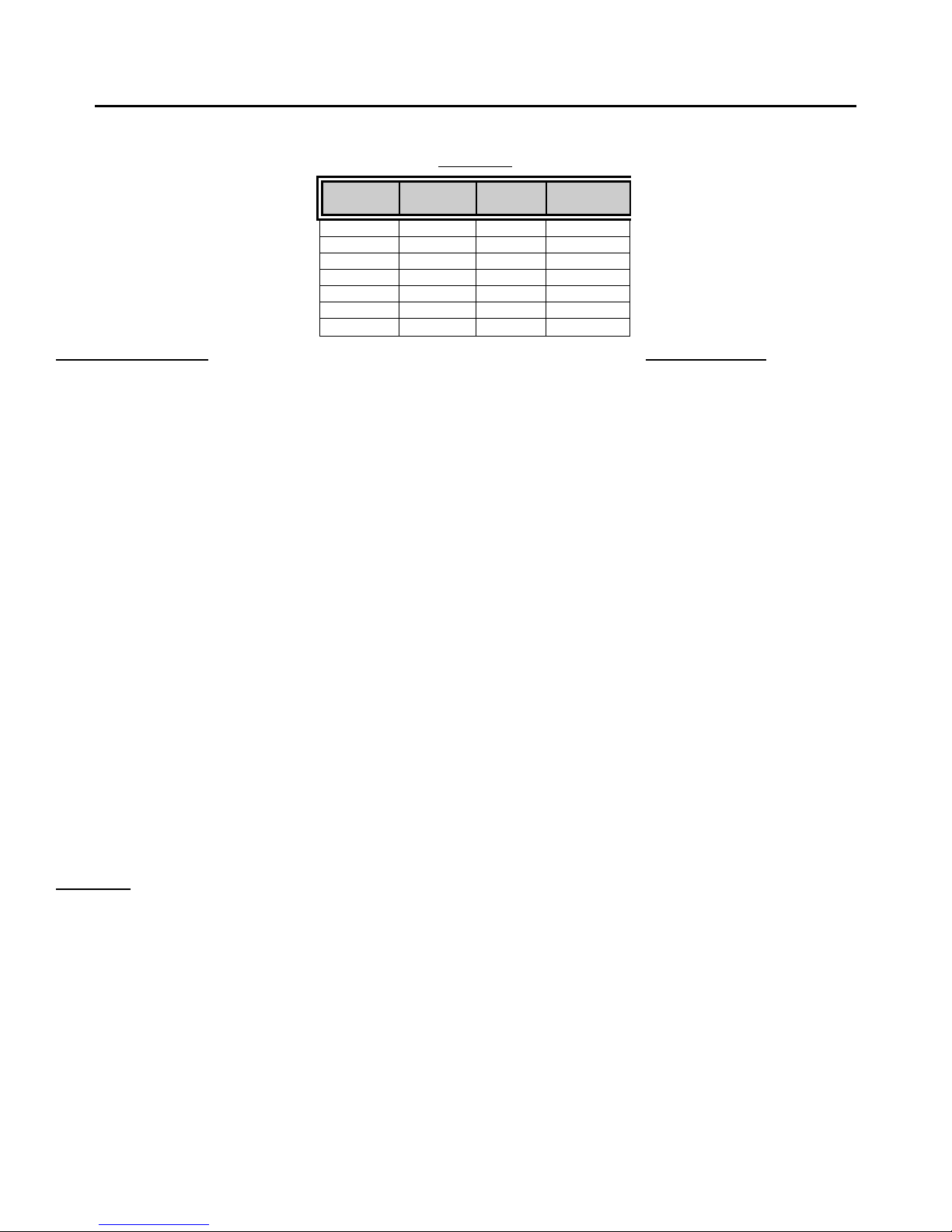
(Before installation, compare electrical needed for the model of heater selected)
TA
BLE 1
Model No. Wattage Voltage Breaker
Size
M-30 6240 208 30A
M-30 7200 220/240 30A
M-30 8310 277 30A
M-40 8320 208 40A
M-40 9600 220/240 40A
M-40 11080 277 40A
M-50 11520 220/240 50A
In
stant - Fl ow Micro
• Dimensions: 6 ¼ ” x 9 5/8 ” x 2 ¾ ”
• Weight: 5 lbs.
• Mater ials: Rugged cast aluminum alloy casing, Celcon waterw ay s w it h nichrome parts
• Color: White (unless stainless steel housing)
• Pipe Fittings: Female ¼” NPT standard pipe thread
• Pressure Requirements: 25 PSI Minimum 150 PSI Maximum (300 PSI test ed) No pressure relief valve needed
unless required by local codes.
• Maximum Operating Temp: 140°F
• Minimum Operating Flow Rate: .65 GPM
* Minimum Operat ing Flow Rate: 1. 0gpm for Models
M-40- 220/ 240, M - 40/277 & M-50- 220/ 240
• Listings: UL, HUD, IAPMO
Specifications:
THE MANUFACTURER OF THIS W ATER HE ATER WILL NO T BE L IABLE FO R ANY DAMAGES
DUE TO THE FAILURE TO FOLLOW THESE INSTALLATION AND OPERATION INSTRUCTIONS.
CAUTION: BEFORE BE GINNING THE INSTALLATIO N:
A) Turn of f the circuit breaker t o avoid dangerous electr ical shocks.
B) Turn of f the water supply.
1. Remove electrical access cover. Attach conduit to the conduit access hole. Then feed wires. Do not attach wiring.
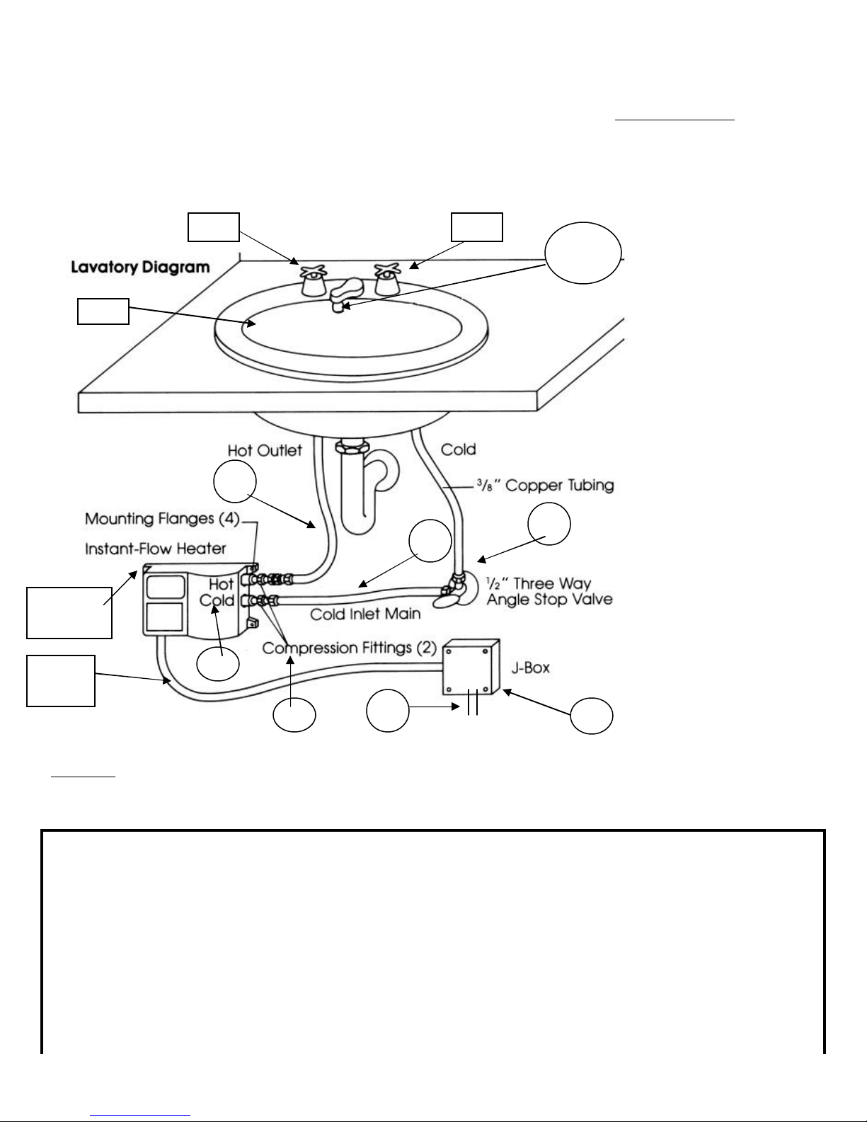
2. M ount unit horizont ally against the wall so the silver label reads cor r ec t ly ( See Fig. 1) . M ount with four screws
through the flanges located on each corner using molly anchors or fasteners.
CAUTI O N: Heating element s may burn out if not mount ed horizontally.
3. Connect plumbing. Use ¼” tapered national pipe thread at cold wat er inlet and hot water outlet ( See Fig. 1) . Use
compression fittings supplied for ease of installation. Do not apply heat to t hese fitt ings.
4. Run water through the unit to expel all air bubbles. Check for leaks at all fitting joints.
5. Connect wiring. Attach ground wire to center terminal and hot wires to outer terminals (See Fig. 3).
6. Replace electr ical access cover. Turn on the circuit breaker . The unit is now ready fo r use.
7. Local plumbing and electrical codes must be followed in the installation of this water heater and it’s accessories.
8. Failure to comply with code requirement s voids the warranty.
Downloaded from www.GadgetsGo.com, Authorized Chronomite Distributor
Page 2
page 1
IMPO RTANT NOTES: Air in the heater may cause the element to burn out. If the water lines are drained,
allowing air into the heater, be sure to follow the following start-up procedure:
1. Turn off electr ical supply at circuit breaker.
2. Turn on water supply.
3. Expel all air from lines and heater.
4. Turn on electrical power supply at circuit breaker .
Mounting
Flange
Sink
Hot
Cold
#9
#10
#8
#5
#7
#3
#1
Conduit
#6
#4
#2
FIGURE 1 HEATER INSTALLATION
Faucet flow controls attached to the faucet allow the water heating system operate more eff ect ively. For example, 2 GPM
flow controls r ecommended for faucets, assure that t he flow rate will not e xceed 2 G PM . However, less water can always
be used. Also, consumers can mix w ith cold water as with a conventional system (See Fig. 2, pg. 3 for I nstallation).
Item Part No. Names Qty Description
1. M-_ _ Chronomite I nstant-Flow M icr o 1 Models shown in Table 1
2. Electrical junction box
3. Electrical conduit ½” conduit, length as required
4. Electrical wire Wire size shown in Table 1
5. Dual outlet angle valve 1 ½” FPx7/16” comp.x3/8 comp., Bras s
Craft P/N R2701R-RGH
6. Fitting (supplied) 2 3/8” comp x ¼”MP
7. Copper or flex tubing 1 3/8” OD, 5” long (keep short)
8. Copper or flex tubing 3/8” O D, length as required (keep short)
9. A-212 Faucet flow control (supplied) 1 dual t hread 15/16” male thread
or and 55/64” female thread (See
Downloaded from www.GadgetsGo.com, Authorized Chronomite Distributor
Page 3

Figure 2)
adapters if needed 3
Note:C=Copper Cup M P=Male Pipe FP=female Pipe STD=Thr ead Comp=Compression Fittings
page 2
OPERATION INSTRUCTIONS
Turn the hot water fixture to activate the flow switch. The flow switch activates at one gallon per minute (GPM) and
deactivates at .65 gallon per minute.
If y o u incre as e the flo w r a te of t he w a ter will be c o me c o o ler. Co ld water can always b e mixed just a s wit h a co nventional
system if using a t w o handle faucet.
Once y ou dec reas e the flo w r a te t o .65 GPM the unit will deact ivate. I t is not advisable to operat e t he heaters at t he
.65 GPM .
>Periodically ins pect t he supply lines, connect ions and heater for any moisture, corrosion or other potential preventable
problems.
HOW INSTANT-FLOW MICRO WORKS
The cast alloy case houses a series of ingeniously designed c oils that instantly heat wat er as it flows t hrough the vessel. A
unique power sw it ch automatically applies elect r ical current to the coils when hot water is being requested. The electrical
current is not applied when the water is not in us e. The microprocessor is internally preset at t he factor y t o maintain a
constant output temperature with varying flow rates.
OPTIONS/ FLOW CONTROLS
You may want to install the supplied flow cont r ol in your design. This high-quality control makes the water heating system
operate more ef f ec t ively, as well as saving water . The supplied 2.0 GPM flow control assures t hat the flow r at e will not
exceed 2 GPM. However, less water can always be used. Consumers can mix t he cold water as with a conventional
system.
LOW FL O W RATE SYSTEM
For applications where a 0.5 GPM f low r at e is desirable and / or w here only 110 VAC is available, see our low f low r at e
system outlined in Installation Sheet #927.
FLO W CONTROL MO DEL S
Model G PM Vandal Proof Models GPM
A-212 (Male/ f emale) 2.0 A-200VR (Male) 2.0
Adapters A-210VR (Female) 2.0
FLOW CONTROL SPECIFICATI O NS
Mater ial: Chr ome plated, br ass housing.
Threading: MODEL A-212 has male (outside) threads f or f aucets
with 15/16” f emale threads and has f emale
(inside) threads for faucets w it h 55/64” male threads.
*Flow controls are adapt able t o ot her thread configurations.
Please use one of the three adapters supplied if needed. FACTORY SET
Please call factory if adapt er is needed and one of t he supplied adapter s does n’t wor k.
FIGURE 2
FLOW CONTROL INSTALLATION (See Parts List #9, #10) Choose from the following:
104 ºF
110 ºF see *** below
120 ºF see *** below
* Other Temperature Settings are
available upon request up to
140 ºF
Page 4

** Temper ature Settings are not
Field adjust able
*** 110 ºF / 120 ºF Temperature
settings are recommended with
cold water mixing faucets
TEMPE RATURE INCREAS E ABOVE INCOMING W ATER TEMPERATURE
MODEL VAC 0.65GPM 1.0 GPM 1.5 GPM 2.0GPM
M-30 208 66°F 42°F 28°F 21°F
M-30 240 64°F 49°F 33°F 25°F
M-30 277 64°F 57°F 38°F 28°F
M-40 208 87°F 57°F 38°F 29°F
M-40 240 xxxx 65ºF 44° F 33°F
M-40 277 xxxx 75° F 50° F 38°F
M-50 240 xxxx 79ºF 55°F 41°F
page 3
Microprocessor limits temperature increase according to
the fact ory set temperature
FIGURE 3 Wiring Connection
TROUBLESHOOTING GUIDE
Your Instant-Flow M icro water heater has no int er nal user serviceable parts and should be r et urned to the factor y f or repair
or replacement. Please contact factory for return authorization. If after following the Installation Instructions, your
Instant-Flow Micr o does not heat wat er in accordance with this literat ure, please check the following:
1. Low Power – Verify your voltage by us ing a voltage meter. You should obtain your reading off t he two outside
terminals located on the heater. Compare this reading against t he voltage specified in the
Installation Instructions. The center terminal is always the earth ground.
2. Low Voltage – The percentage of r eduction in voltage will res ult in a lik e reduction in temperature incr ea s e .
3. Check Low Amperage Draw – Check amperage draw using an Amperage Probe. Please compare your
results with the Installation Instruction (Table 1) to determine if the heat er is oper at ing correct ly.
4. Length of Pipe - L engt h of pipe run will affec t t he t e mpe rat ure incr e a s e . The heate r should be mounted no
more the 12-18 inches from the point of use.
5. Check shut – off valve – Check shut- off valve and make sure valve is open 100% to allow full water pr essure
to the heater.
6. Check Flow Rate – Cont rolling f low r a te is es s e nt ial to insure p rope r t emp erature incr e as e . Check y o ur flow
rate t o insure proper operat ion of the heater. Standard Flow Rate M odels require 1.0 G PM to activate.
7. Installation – Heater must b e installed in a horizonta l po s ition. T he silver la b el will t hen be loc a ted in t he upper
left corner as you face the heater.
8. Water Supply – Cold water supply to only feed Instant-Flow Micro cold w at er inlet.
9. Freezing – Instant-Flow Micr o heaters must be drained and stored if in a location subject t o freezing.
Disconnect the inlet/ outlet compress ion fittings and blow air through one side of t he heater to assist dr aining.
Failure to co mple tely r e move water fr o m t he unit w ill r e s ult in f reezing and cr ac k ing.
10. Problems? – Call our t oll-f r ee hotline 800/447-4962 or 626-937- 4270.
Your Instant-Flow Micro water heater has been engineered and built to the highest quality standards and i s backed by
a full, factory warranty. Every Instant-Flow Micro water heater is guaranteed to be free from defects in material and
workmanship for a period of one (1) year from the date of purchase. The above warranty applies to origin al purc haser
if unit is installed to Chronomite Laboratories, Inc.’s Installation Instructions. Chronomite Laboratorie s, Inc. will repair
or exchange part s at the f act or y at no cost . This warrant y is limited to repairing or replacing said products which
prove to be def ect ive upon fact or y inspection, F.O.B. City of Industry, California.
EXCL US IVE 12-MONT H WARRANTY
Page 5

Chronomite Laboratories Inc.
17451 Hurley Street.
City of Industry, CA 91744
Toll Free Technical Hotline 800-447-4962 T elephone 626-937- 4270
Fax 626-937-4279
#928 02/05 rev.7 page 4
Downloaded from www.GadgetsGo.com, Authorized Chronomite Distributor
 Loading...