

Chronomite M-15L, M-30L, M-40L, M-20L, M-30 Installation And Operation Instructions Manual
...Page 1
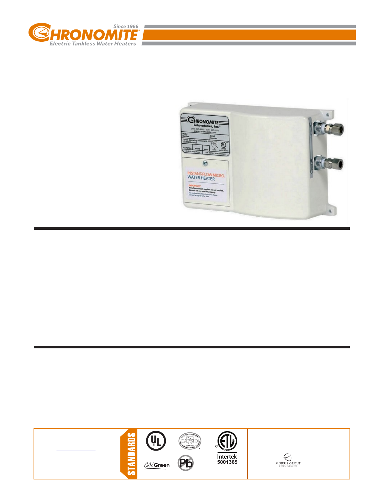
ELECTRIC TANKLESS WATER HEATER - POINT OF USE
INSTANT-FLOW MICRO
®
WATER HEATER
INSTALLATION AND OPERATION
INSTRUCTIONS (LOW ACTIVATION
MODELS)
Chronomite Laboratories is a Member of Morris Group International™
TABLE OF CONTENTS
Technical Information
Dimensional Data . . . . . . . . . . . . . . . . . . . . . . . . . . . . . . . . . . . . . . . . 3
Installation . . . . . . . . . . . . . . . . . . . . . . . . . . . . . . . . . . . . . . . . . . . . 4-5
Specifications . . . . . . . . . . . . . . . . . . . . . . . . . . . . . . . . . . . . . . . . . . . 6
Troubleshooting . . . . . . . . . . . . . . . . . . . . . . . . . . . . . . . . . . . . . . . . . 7
Warranty Information . . . . . . . . . . . . . . . . . . . . . . . . . . . . . . . . . . . . . 8
. . . . . . . . . . . . . . . . . . . . . . . . . . . . . . . . . . . . . 2
REQUIRED ITEMS FOR INSTALLATION
NOT SUPPLIED
? Electrical Junction Supply Box
? Electrical Supply Conduit
? Electrical Supply Wire
? Dual Outlet Angle Stop
? 3/8” Flex Hose or 3/8” O.D. Tubing (2)
? Carpenters Level
? Flat Head Screwdriver
? Phillips Head Screwdriver
Acorn Engineering Company™ assumes no
responsibility for use of void or superseded data.
© Copyright Acorn Engineering, City of Industry,
CA Member of Morris Group International.
Please visit for most
current specifications.
3100-003-001
II-927 06/17 REV 9
www.chronomite.com
COMPLIES WITH
Federal
Public Law
111-380
(No Lead)
Member of
CHRONOMITE
Instantaneous
Water Heaters
17451 Hurley St.
City of Industry, CA
91744 U.S.A.
Phone 800-447-4962
w w w. ch r o n o m i t e . c o m
626-937-4270
Page 2

MODEL VOLTAGE ACTIVATION .80 GPM [3.0 LPM] 1.0 GPM [3.8 LPM] 1.2 GPM [4.5 LPM]
M-15L 277 0.35 GPM [1.3 LPM] 35°F [20°C] 28°F [16°C] 24°F [13°C]
M-20L 120 0.35 GPM [1.3 LPM] 20°F [11°C] - M-20L 208 0.35 GPM [1.3 LPM] 36°F [20°C] 28°F [16°C] 24°F [13°C]
M-20L 240 0.35 GPM [1.3 LPM] 41°F [23°C] 33°F [18°C] 27°F [15°C]
M-20L 277 0.35 GPM [1.3 LPM] 47°F [26°C] 38°F [21°C] 32°F [18°C]
M-30L 120 0.35 GPM [1.3 LPM] 31°F [17°C] 25°F [14°C] 20°F [11°C]
M-30L 208 0.35 GPM [1.3 LPM] 53°F [30°C] 43°F [24°C] 36°F [20°C]
M-30L 240 0.35 GPM [1.3 LPM] 61°F [34°C] 49°F [27°C] 41°F [23°C]
M-30L 277 0.35 GPM [1.3 LPM] 71°F [39°C] 57°F [32°C] 47°F [26°C]
M-40L 208 0.35 GPM [1.3 LPM] 71°F [39°C] 57°F [32°C] 47°F [26°C]
M-40L 240 0.35 GPM [1.3 LPM] 82°F [46°C] 66°F [36°C] 55°F [30°C]
INCOMING WATER TEMPURATURE INCREASE
MODE L WATTAGE VOL TAGE AMPS MODE L WATTAGE VOL TAGE AMPS
ELECTRIC TANKLESS WATER HEATER - POINT OF USE
®
Chronomite Laboratories is a Member of Morris Group International™
INSTANT-FLOW MICRO
SPECIFICATIONS
(LOW ACTIVATION MODELS)
MICROPROCSSOR LIMITS TEMPERATURE INCREASE ACCORDING TO FACTORY SET TEMPERATURE.
BR EAKER S IZE BR EAKER S IZE
INTE RMITTENT
DU TY
M-15 L 41 50 27 7 15 15 20 M-30 L 62 40 2 08 3 0 30 40
M-20 L 24 00 12 0 20 20 30 M-30 L 72 00 2 40 3 0 30 40
M-20 L 41 60 20 8 20 20 30 M-30 L 83 20 2 77 3 0 30 40
M-20 L 48 00 24 0 20 20 30 M-40 L 83 20 2 08 4 0 40 50
M-20 L 55 40 27 7 20 20 30 M-40 L 96 00 2 40 4 0 40 50
M-30 L 36 00 12 0 30 30 40
CONTIN U OUS
TABLE 1
DU TY
!
IMPORTANT
Before installation of heater, review electrical
requirements needed for model of heater
selected.
INTE RMITTENT
DU TY
CONTIN U OUS
DU TY
NOTE: BEFORE INSTALLATION, COMPARE ELECTRICAL
NEEDED FOR THE MODEL OF HEATER SELECTED.
INSTANT-FLOW MICRO SPECIFICATIONS:
DIMENSIONS: 6-1/4” [159 mm] X 9-5/8” [244 mm] X 2-3/4” [70 mm]
WEIGHT: 5 LBS. [2.27 Kg]
MATERIALS: ALUMINUM HOUSING, CELCON WATERWAYS, NICHROME PARTS
COLOR: WHITE
PIPE FITTINGS: 3/8” COMPRESSION
OPERATING PRESSURE RATING: 25 PSI [172 kPa] MINIMUM, 80 PSI [551.6 kPa] MAXIMUM
MAXIMUM PRESSURE RATING: 150 PSI [1034.2 kPa] NO PRESSURE RELIEF VALVE NEEDED
MAXIMUM OPERATING TEMP: 160°F [71°C]
MINIMUM OPERATING FLOW RATE: 0.35 GPM [1.3 LPM]
LISTINGS: UL, HUD, IAPMO, UPC, ETL
FACTORY SET TEMPERATURES:
104°F [40°C]
110°F [43.3°C]
120°F [48.9°C]
Other temperature settings are available upon request up to160°F [71°C]. Temperature settings are not field adjustable. 110°F
[43.3°C] / 120°F [48.9°C] settings are recommended with cold water mixing faucets.
HOW INSTANT-FLOW MICRO WORKS
The engineered plastic case houses a series of ingeniously designed coils that instantly heat water as it flows through the vessel. A
unique power switch automatically applies electrical current to the coils when hot water is requested. The electrical current is not applied
when the water is not in use. The microprocessor is internally preset at the factory to maintain a constant output temperature with
varying flow rates.
3100-003-001
II-927 06/17 REV 9
®
UNLESS REQUIRED BY LOCAL CODES.
®
CHRONOMITE TECHNICAL SUPPORT
TOLL FREE 800-447-4962 • LOCAL 626-937-4270 • FAX 626-937-4279
Page 2 of 8
Page 3
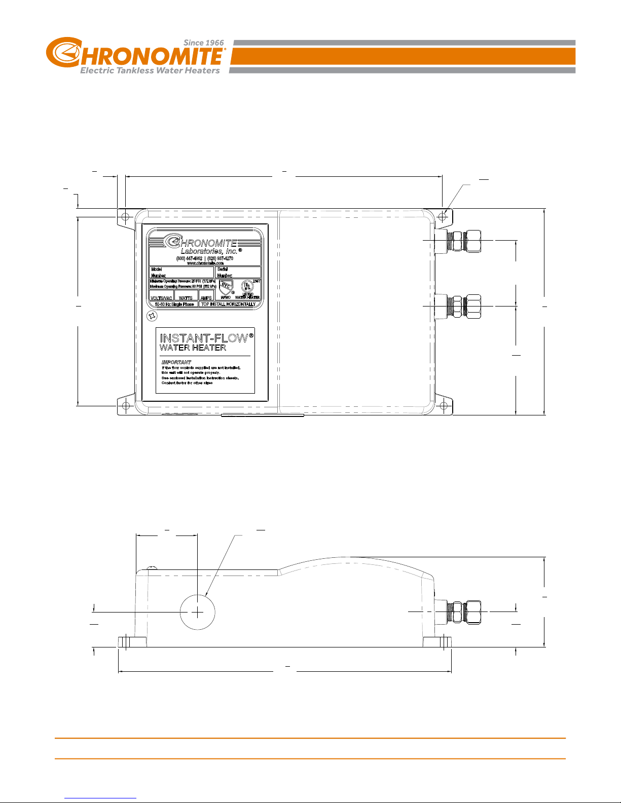
ELECTRIC TANKLESS WATER HEATER - POINT OF USE
INSTANT-FLOW MICRO
®
DIMENSIONAL DATA
1
"
4
1
[6]
"
4
[6]
3
5
"
4
[146]
5
9
8
[244]
Chronomite Laboratories is a Member of Morris Group International™
"
7
Ø
"
32
[6]
2"
[51]
1
6
"
4
[159]
5
3
"
16
[84]
7
1
"
8
[48]
1
1
"
16
[27]
3100-003-001
II-927 06/17 REV 9
1
Ø1
"
16
[27]
1
[27]
1
10
"
8
[257]
TOLL FREE 800-447-4962 • LOCAL 626-937-4270 • FAX 626-937-4279
Page 3 of 8
CHRONOMITE TECHNICAL SUPPORT
16
3
2
"
4
[70]
1
"
Page 4

ELECTRIC TANKLESS WATER HEATER - POINT OF USE
Chronomite Laboratories is a Member of Morris Group International™
!
CAUTION
A) Turn off the circuit breaker to avoid
dangerous electrical shocks.
8
B) Turn off the water supply.
C) Do not apply heat to inlet or outlet fittings on
heater. Do not solder direct.
D) Flush supply line of all foreign material such as
pipe dope, pipe chips, solder, sand, etc. before
making up supply connections after working on
water piping.
SILVER LABEL
1
3
OR
7
6
7
ENSURE THIS 2nd
HOSE DOES NOT
GO BELOW DATUM
LINE
DATUM LINE
5
Chronomite Instant-Flow Micro See page
1
2 for selection
Electrical junction supply box (optional)
2
2A
2095-1 Disconnect Switch (optional)
3
Electrical supply conduit
4
Electrical supply wire
5
Dual outlet stop 3/8” Comp outlet
connections
6
2
4
2A
FIGURE 1 INSTALLATION LAYOUT
Fittings (supplied) 3/8” Comp x 1/4” NPT
7
Faucet Supply inlet hoses 3/8” NPS
8
Flow control (supplied) Dual threads
15/16” male and 55/64” Female
HEATER INSTALLATION:
1. Remove cover off of water heater. Attach conduit to the conduit connection punching. Then feed wires. Do not attach
wiring.
2. Mount unit horizontally against the wall so the silver label reads correctly (See Figure 1). Use level to ensure unit is level
and mount with four screws through the flanges located on each corner using molly anchors or fasteners.
3. Connect plumbing. Use female 1/4” NPT or hose with 3/8” compression at cold water inlet and hot water outlet to 3/8”
compression faucet inlet connections (See Figure 1). DO NOT APPLY HEAT TO THESE FITTINGS.
4. Run water through the unit to expel all air bubbles. Cycle hot side of faucet 10 times to assist in removing air bubbles.
Check for leaks at all fitting joints. If no leaks proceed to electrical installation.
CAUTION: HEATING ELEMENTS MAY BURN OUT IF UNIT IS NOT MOUNTED HORIZONTALLY
ELECTRICAL INSTALLATION:
1. Connect power supply wires appropriately sized and protected by circuit breaker to the input terminals on the heater (hard
wired) as shown in the Figure 2 wiring diagram.
2. Refer to Table 1 above on Page 2 for the voltage and amperage of the supply power.
3. Ensure each wire L2/N, G, L1 are connected to the respective terminals. Only connect to rated voltage on nameplate.
4. Ensure water inlet valve to heater is fully open. Do not throttle inlet
5. Turn on circuit breaker. Turn on water flow to exceed activation point listed in chart 2. The unit is almost ready for use.
Shut off circuit breaker.
6. Check for leaks at all fitting joints and also inside heater.
7. Install cover. Turn on circuit breaker. Unit is now ready for use.
8. Local plumbing and electrical codes must be followed in this installation of water heater and the accessories.
NOTES:
1. Failure to comply with code requirements voids the warranty.
2. Failure to install faucet flow control as shown on (Figure 3 page 6) may cause unsatisfactory operation of the heater.
3100-003-001
II-927 06/17 REV 9
TOLL FREE 800-447-4962 • LOCAL 626-937-4270 • FAX 626-937-4279
CHRONOMITE TECHNICAL SUPPORT
Page 4 of 8
Page 5

ELECTRIC TANKLESS WATER HEATER - POINT OF USE
INSTANT-FLOW MICRO
®
INSTALLATION (cont.)
!
IMPORTANT
The manufacturer of this water heater will not be liable
for any damages due to the failure to follow these
installation and operation instructions.
ATTENTION:
UNIT MUST BE
HARD WIRED
TERMINATION RODS
BRASS NUTS
GND
Chronomite Laboratories is a Member of Morris Group International™
HI-LIMIT THERMOSTAT
"GND" IS EARTH GROUND
L2/N (L2 FOR 208 & 240V UNITS
N FOR 120 & 277V UNITS
CONDUIT CONNECTION PUNCHING
STRAIN RELIEF NOT SHOWN FOR CLARITY
SEE ELECTRICAL SPECIFICATIONS
FOR CORRECT WIRE SIZE.
NOTE:
HEATERS ARE SINGLE PHASE. ALL TESTS ARE
MEASURED AT THE OUTPUT OF THE HEATER.
FIGURE 2 WIRING CONNECTION
!
NOTICE
Air in the heater may cause the elements to burn out.
If the water lines are drained, allowing air into the
heater, be sure to follow the following start-up
procedure:
START UP PROCEDURE:
1. Turn off electrical supply - open circuit breaker
2. Turn on water supply. Cycle hot side of faucet 10 times to assist in removing air bubbles.
3. Expel all air from lines and heater. Check for leaks at all fittings, joints and at water heater.
4. Turn on electrical power supply - close circuit breaker.
L1
3100-003-001
II-927 06/17 REV 9
TOLL FREE 800-477-4962 • LOCAL 626-937-4270 • FAX 626-937-4279
CHRONOMITE TECHNICAL SUPPORT
Page 5 of 8
Page 6

KW
104°F ***110°F ***120°F
Notes:
*
**
***
FACTORY SET TEMPERATURES
Other Temperature Settings are available upon
request up to 140°F
Temperature Settings are not Field Adjustable
110°F / 120°F Temperature Settings are not
recommended w ith metering / sensor faucets
(cold w ater mix needed)
ELECTRIC TANKLESS WATER HEATER - POINT OF USE
Chronomite Laboratories is a Member of Morris Group International™
®
INSTANT-FLOW MICRO SPECIFICATIONS
(LOW ACTIVATION MODELS)
OPERATION INSTRUCTIONS:
Ÿ Turn the hot water fixture to activate the flow switch. The flow switch activates at 0.35 gallons per minute (GPM) [1.3 LPM] and
deactivates at 0.30 gallons per minute (GPM) [1.1 LPM].
Ÿ If you increase the flow rate of the water above the KW capacity, the water temperature will become cooler. Cold water can always be
mixed just as with a conventional system if using a two handle faucet. Select the appropriate flow control.
Ÿ Once you decrease the hot water flow rate to 0.30 GPM [1.3 LPM] the unit will deactivate. It is not advisable to operate the heater
at 0.30 GPM [1.3 LPM] hot water flow rate.
NOTES:
1. Periodically inspect (4 times a year) the supply lines, connections and heater for any moisture, corrosion or other potential
preventable problems.
2. Prior to shutting off water valves for servicing, winterization, etc, always disconnect power from unit 1st.
3. Unit is intended to heat water only, and does not provide a means of cooling if inlet temperature exceeds set point temperature of
heater.
OPTIONS:
• PA 765 ABS Housing (P) • Pressure & Temp. Relief Valve Assembly (TP)
• Satin Finish Stainless Steel Housing (SS) • 1/2” Male NPT (NPT08)
• High Polish Finish Stainless Steel (SSP) • Disconnect Switch, Rotary 40A - Lockable Nema 4X (2095-1)
FLOW CONTROLS:
You may want to install the supplied flow control in your design. This high-quality control makes the water heating system operate more
effectively, as well as save water. the supplied GPM [LPM] flow control assures that the flow rate will not exceed GPM [LPM], however, less
water can always be used. Consumer can mix the cold water as with a conventional system. See Flow Control Models Chart below.
LOW FLOW RATE SYSTEM:
For applications where 0.20 - 0.35 GPM (0.75 - 1.3 LPM) Flow Rate is
desirable, see our CM series heaters.
FLOW CONTROL SPECIFICATIONS
MATERIAL: Chrome plated, brass housing.
THREADING: DUAL threads 15/16” male
NOTE: Flow controls are adaptable to other thread configurations.
Vandal resistant models are available. Please call factory
If adapter or vandal resistant model is needed.
1.8 - 3.6 AP-1-P
4.0 - 5.0 AP-2-P
6.0 - 12.0 AP-3-P
3100-003-001
II-927 06/17 REV 9
55/64” female
FLOW CONTROL MODELS CHART
ACCESSORY
PACKAGE
45 psi 45 psi
≥
L412-0.5-NP
0.5 GPM SPRAY
A412-1.0-NP
1.0 GPM LAMINAR
A412-2.0-NP
2.0 GPM LAMINAR
!
NOTICE
•Flow controls are adaptable to other
thread configurations. Please call
factory if adapter is needed.
FIGURE 2
FLOW CONTROL
INSTALLATION
(See Parts List #8)
<
L412-1.0-NP
1.0 GPM SPRAY
A412-1.5-NP
1.5 GPM LAMINAR
-
TOLL FREE 800-447-4962 • LOCAL 626-937-4270 • FAX 626-937-4279
Page 6 of 8
!
IMPORTANT
Periodically inspect (4 times a year) the supply
lines, connections and heater for any moisture,
corrosion or other potential preventable problems.
CHRONOMITE TECHNICAL SUPPORT
Page 7

ELECTRIC TANKLESS WATER HEATER - POINT OF USE
Chronomite Laboratories is a Member of Morris Group International™
®
INSTANT-FLOW MICRO
TROUBLESHOOTING GUIDE
TROUBLESHOOTING GUIDE
Your Instant-Flow Micro water heater has no internal user serviceable parts and should be returned to the factory for repair or
replacement. Please contact factory for return authorization. If after following the Installation Instructions, your Instant-Flow
MICRO does not heat water in accordance with this literature, please check the following:
1. Low Power – Verify your voltage by using a voltage meter. You should obtain your reading off the two outside terminals
located on the heater. Compare the reading against the voltage specified in the Installation Instructions. The center
terminal is always the earth ground. The hot and neutral legs, in the case of 110 V heaters, are attached on the two
outside terminals.
2. Low Voltage – The percentage of reduction in voltage will result in a like reduction in temperature increase.
3. Check Low Amperage Draw – Check amperage draw using an Amperage Probe. Please compare your results with
the Installation Instructions (Table 1) to determine if the heater is operating correctly.
4. Length of Pipe - Length of pipe run will affect the temperature increase. The heater should be mounted no more than
12-18 inches [ 305mm-457mm] from the point of use.
5. Check shut off valve. Check shut-off valve and make sure valve is open 100% to allow full water pressure and flow to
the heater.
6. High-Limit Thermostat - Shut off power on breaker. Remove cover. Push in reset button on module. Refer to Figure
2 for location. Reinstall cover. Turn on breaker. If problem persists, contact factory.
7. Heater Element - Shut off power on circuit breaker. Remove cover. Measure element resistance by using an
ohmmeter or multi-meter. Obtain your reading off of termination rods with brass nuts on each heater module. Refer to
Figure x for location. This reading should be between 6 and 30 ohms for each element.
8. Check Flow Rate – Controlling flow rate is essential to insure proper temperature increase. In the case of the low flow
rate heater it is mandatory that the flow control be attached to the end of the faucet. Check your flow rate to insure
proper operation of the heater. Low Flow Rate Models require 0.35 GPM (1.3 LPM) to activate.
9. Installation – Heater must be installed in a horizontal position. The silver label will then be located in the upper left
corner as you face the heater.
10. Water Supply – Do not throttle water supply to inlet of Instant-Flow MICRO. Operating conditions shall not exceed
specification on page 2.
11. Freezing – Instant-Flow MICRO heaters must be drained and stored if installed in a location subject to freezing.
Disconnect the inlet/outlet compression fittings and blow air through one side of the heater to assist draining. Failure to
completely remove water from the unit will result in freezing and cracking.
12. Problems?- Call our toll-free hotline 800-447-4962 or 626-937-4270
WARNING
- This water heater is not intended for use by persons (including children) with reduced physical, sensory or
mental capabilities, or lack of experience and knowledge, unless they have been given supervision or
instruction concerning use of the water heater by a person responsible for their safety.
- Children should be supervised to ensure that they do not play with the water heater.
- The water resistivity must not be less than 1100 OHM-CM.
- The water heater must be earth grounded.
- The water heater is not to be installed in locations where freezing can occur.
3100-003-001
II-927 06/17 REV 9
TOLL FREE 800-447-4962 • LOCAL 626-937-4270 • FAX 626-937-4279
CHRONOMITE TECHNICAL SUPPORT
Page 7 of 8
Page 8

ELECTRIC TANKLESS WATER HEATER - POINT OF USE
Chronomite Laboratories is a Member of Morris Group International™
M A IL A D D R E S S
P. O . B O X 3 5 2 7
C I T Y O F I N D U S T R Y, C A 9 1 7 4 4 U . S . A.
P H Y S I C A L A D D R E S S
1 7 4 5 1 H U R L E Y S T R E E T
C I T Y O F I N D U S T R Y, C A 9 1 7 4 4 U . S . A.
T O L L F R E E 8 0 0 - 4 4 7 - 4 9 6 2 • L O C A L 6 2 6 -9 3 7 - 4 2 7 0
FA X 6 2 6 - 9 3 7 - 4 27 9 • W EB w w w. c h r o n o m i t e . c o m
WARRANTY INFORMATION
Your Instant-Flow Micro water heater has been engineered and built to the highest quality standards and is backed
by a full, factory warranty. Every Instant-Flow MICRO water heater is guaranteed to be free from defects in material
and workmanship for a period of (1) year from the date of purchase. The above warranty applies to original
purchaser if unit is installed per Chronomite Laboratories, Inc.’s Installation Instructions. Chronomite Laboratories,
Inc. will repair or exchange parts at the factory at no cost. This warranty is limited to repairing or replacing said
products which prove to be defective upon factory inspection, F.O.B. City of Industry, California.
EXCLUSION OF COVERAGE FROM THIS LIMITED WARRANTY:
1. Chronomite is not liable under this limited warranty or otherwise if the water heater has not been installed or
maintained in accordance with Chronomite's printed instructions or installed with improper installation materials.
In addition, the water heater or any of its component parts have been subject to misuse, neglect, alteration or
accident and the water heater has not been installed in accordance with the applicable local plumbing and or
building codes and/or regulations.
2. Chronomite is not liable under this warranty if the water heater has not been continuously supplied with potable
water or the water inlet temperature is above Chronomite's recommended maximum temperature. In addition,
water heater experiences any water pressure or flow interruptions, normal operation inlet water pressure is
outside of the published specification (UPC 2009), or exposed to any condition that causes the heater to turn on
before the air is purged from the heater also known as “dry fire.”
3. Chronomite is not liable if the water heater has been exposed to conditions resulting from floods, earthquakes,
winds, fire, freezing, lightning or circumstances beyond Chronomite's control, or has been used for other than the
intended purpose.
If violation occurs from the stated exclusions of coverage from this limited warranty or thereafter; owner,
and not Chronomite or its agent/representative, is liable for and shall pay for all field charges, labor, water
heater, damage or other expenses incurred in the repair or replacement of the water heater.
3100-003-001
II-927 06/17 REV 9
TOLL FREE 800-447-4962 • LOCAL 626-937-4270 • FAX 626-937-4279
CHRONOMITE TECHNICAL SUPPORT
Page 8 of 8
 Loading...